Workbench/Outfeed Table Work Surface

UPDATE:

I’ve tested this for almost a year.  Read my final opinion here.


Behind my table saw is a large outfeed/assembly table that consists of a torsion box top that sits a little bit lower than my table saw.  Since this table is used for glue-up, finishing, andlots of other destructive activites, I have a sacrificial work surface that sits on top of the table and takes my abuse rather than destroying my torsion box.

Removing the Existing Work Surface

My current work surface has seen better days.  It’s probably time to replace it.  In reality, it’s actually not that bad, I’m just sick of the sight of it.

My old work surface is pretty beat up.


I typically use a sheet of 1/8″ hardboard that sits loosely on top of the torsion box which is made out of MDF and finished with a few layers of polyurethane.

My work surface is usually a sheet of 1/8" hardboard.


By using a sacrificial work surface I am able to keep the actual bench-top relatively nice looking and flat.

The torsion box top of my workbench is usually well protected by my sacrificial work surface.


Laying Out and Sizing the New Work Surface

I originally wanted to change things up and replace it with a sheet of hardboard with a smooth white coating, sometimes referred to as markerboard.  My reasoning was that glue and paint could be easily scraped off.  When I went to the local big-box home store, I saw a material I hadn’t worked with yet and I decided to give it a try.

I got a sheet of PolyWall, which is advertised as being a good way to protect walls.  It’s thinner than hardboard and has a slight texture to it.  The sheet is larger than my bench-top which measures 30″ deep and 8′ in length.  I’ll need to cut this down.

The sheet of PolyWall is too big for my workbench.


My workbench is actually a little longer than 8′.  This will actually help me cut it down as you’ll see in a later step.  For now, I leave a little bit of the workbench exposed on each end.  To make sure I trim this down squarely, I am using a combination square on one side and set the new work surface  the same distance from the edge of the workbench all along that end.

Lining up the edges so it's square with the workbench top.


Now I’m using something to hold the new work surface down.  For this I just grabbed one of my cauls and clamped it down with some quick release clamps.  I did this on each end.

I clamped down the new work surface with a caul on each edge to hold it flat.


Then I clamped a straightedge along the front edge.  This is where it helps to have the workbench stick out from under the work surface.  Since my straightedge is also a little bit longer than 8′ in length, I used the workbench to line up the straightedge and clamp it down on each end.

Lining up a straightedge to cut along.


Cutting this material is really simple.  I just ran a utility knife along the straightedge to score the material, then repeated a few times until it simply fell away.

It took about 3 passes with a utility knife to completely cut through the material.


The finished edge has a slight burr to it that can be removed with a file, sandpaper, or a scraper.

The freshly cut material leaves a slight burr.


After that I moved the straightedge to the back of the workbench and repeated the process there.  To simplify, I could have just lined up one of the factory edges of the material with either the front or back of the workbench top but I just felt like doing it this way.

Repeating the process along the back edge.


Securing the New Work Surface

That’s all the cutting I’m going to need to do.  As you can see, the material likes to raise up at the far edges.  This is because I had to roll up the sheet to fit in my car when I bought it and it tends to have a memory to it that fades with time.  I can fix this by simply letting the sheet lay on the workbench for a few hours.

All cut down.


To keep the sheet from slipping, I am applying some strips of double-stick tape between the benchtop and work surface.


Applying some double-sided tape to help prevent the new work surface from slipping.


Now we have it.

All done.


I’ve never used this material as a work surface before.  I’m going to test it out for a few months under normal use and report back with how it works.  So far, I like the slightly textured surface since it causes the material to glide across it much easier.  I’m mostly concerned with the toughness.  It seems pretty tough but awfully thin.  I’ll let you know how this holds up.


Have you ever used this material for anything?  What do you put on the top of your workbench?  Share it with us in the comments below.


UPDATE:

I’ve tested this for almost a year.  Read my final opinion here.

The extension wing provides a lot of work surface.

Workbench: Part 7 – Installing The Hardware


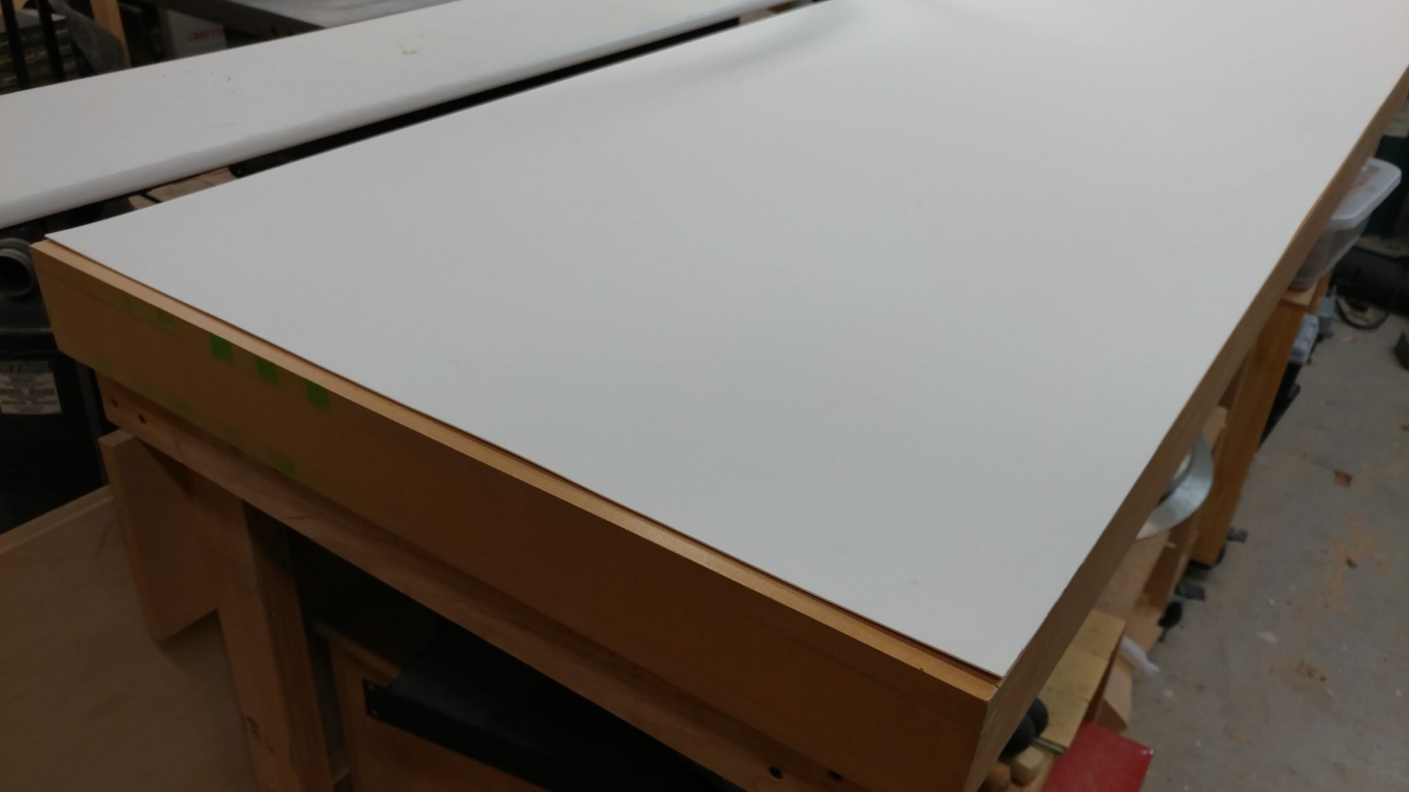
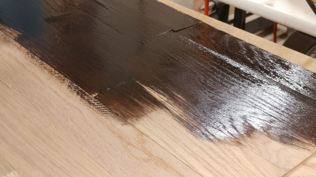
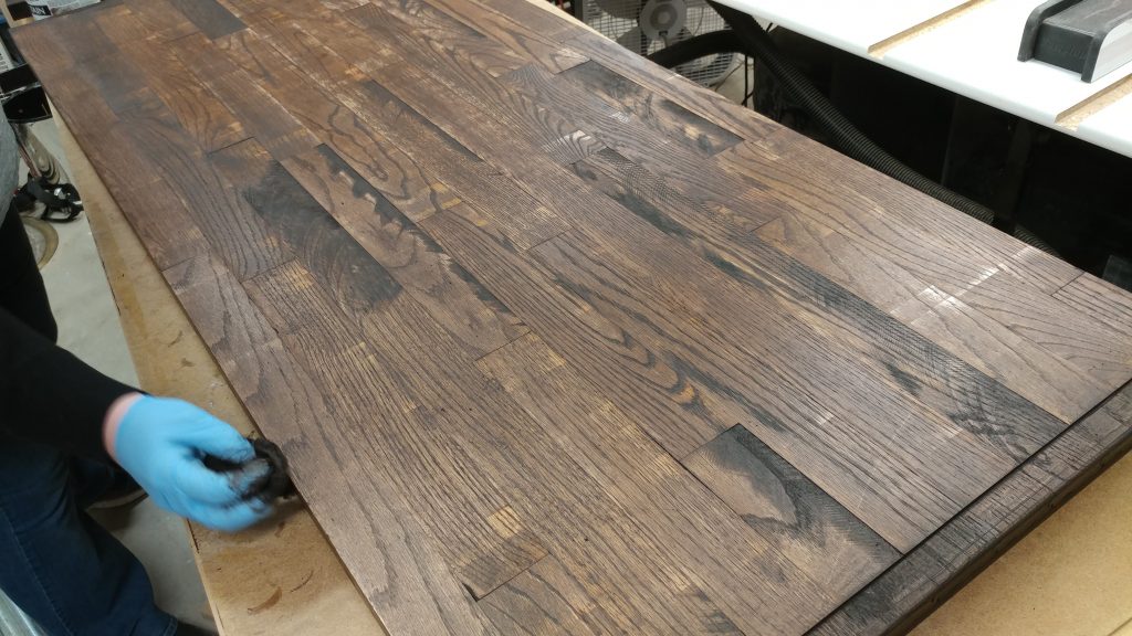
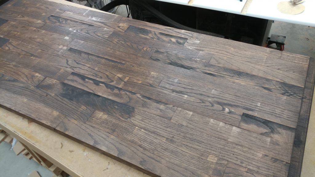
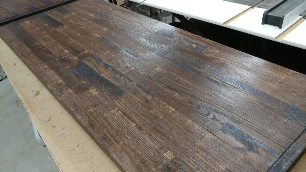
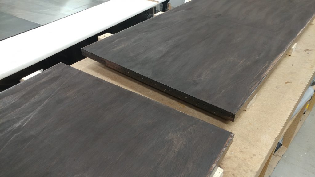
<< This is a continuation of Workbench: Part 6 – Finishing the benchtop


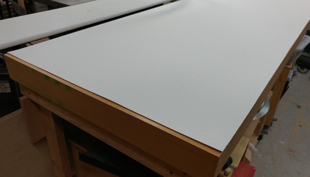
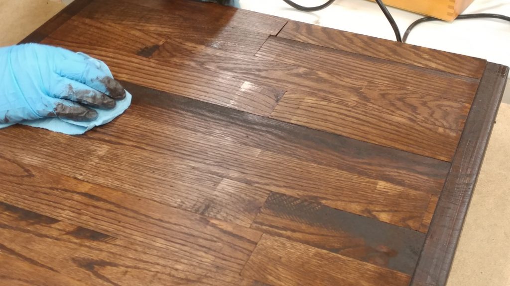
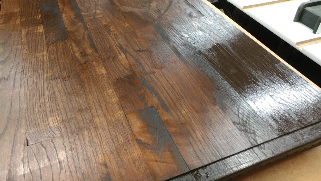
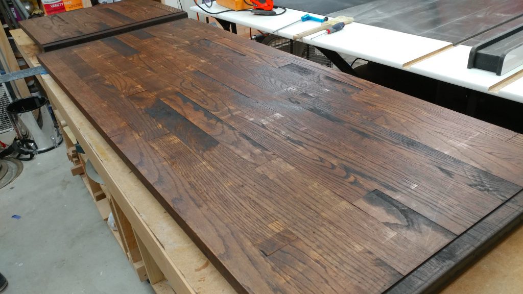
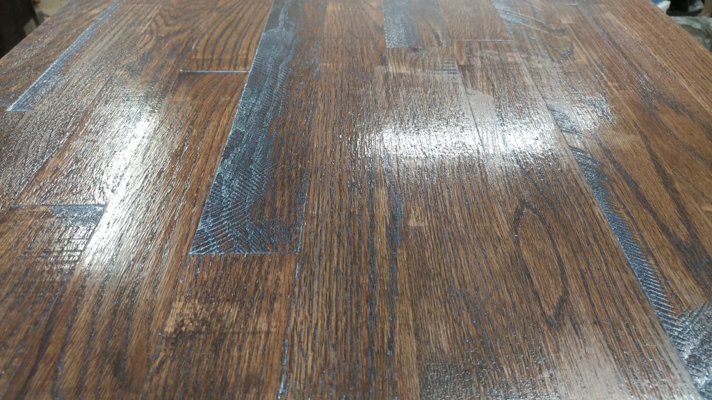
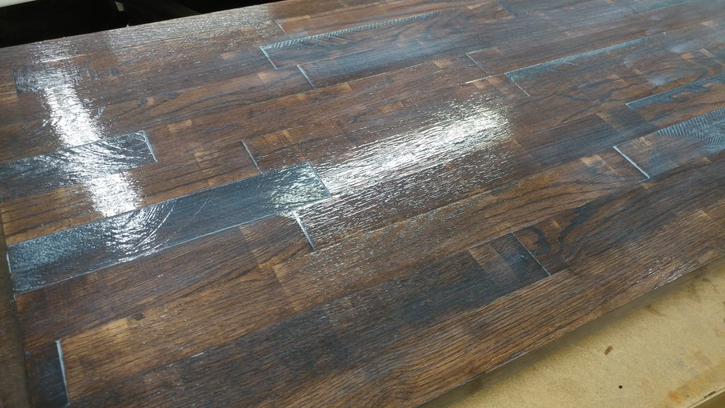
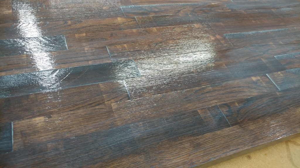
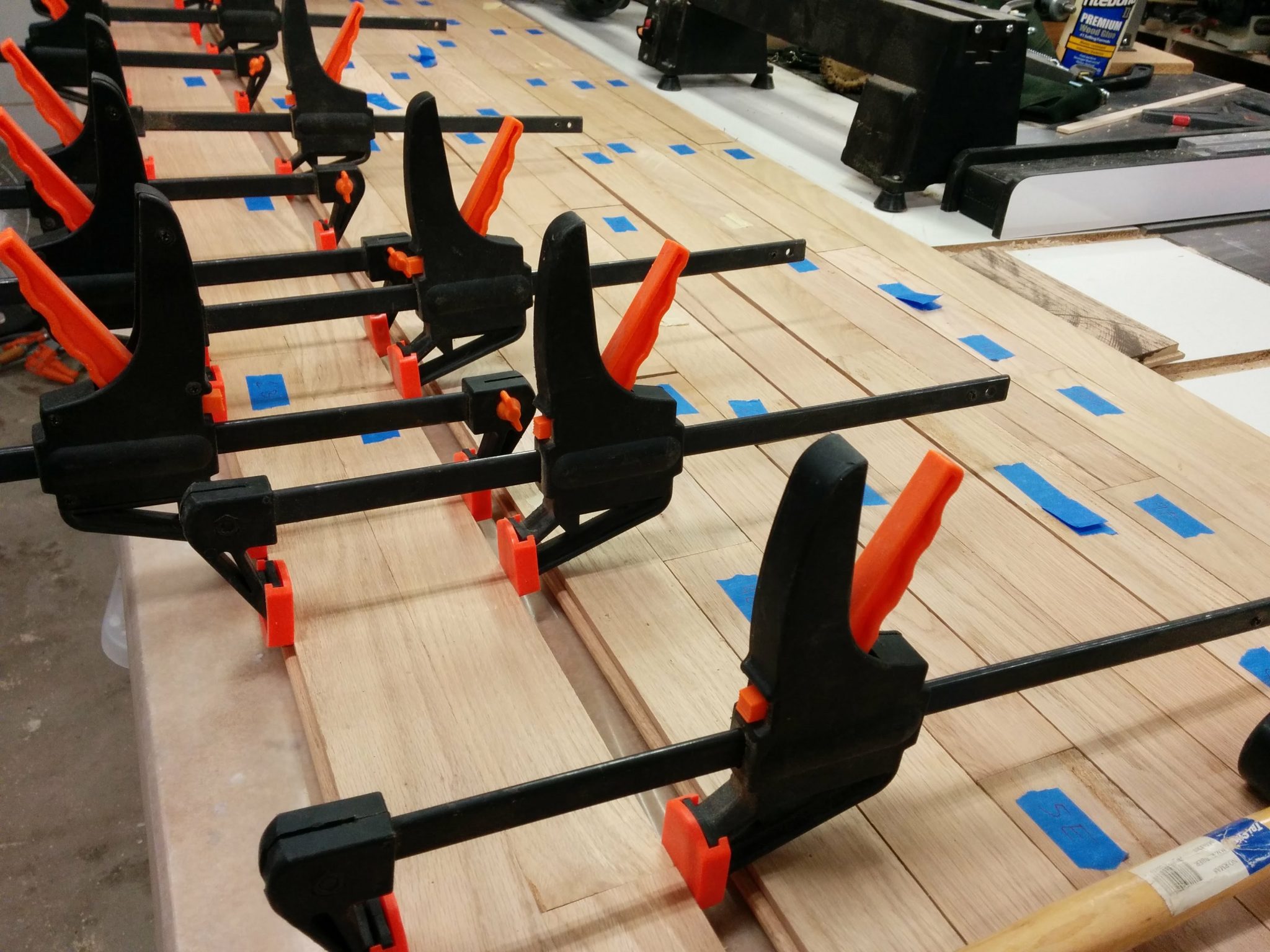
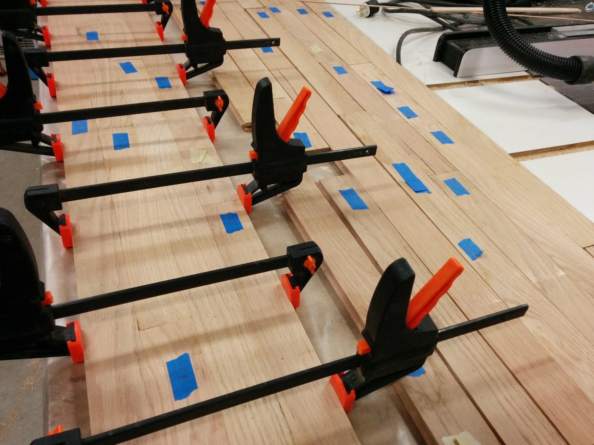
The finish has been applied to the bench-top so now it’s time to attach the hardware.  This is a tricky subject to explain clearly.  I’m going to do my best but I’m planning on coming back and editing this post a bit in an effort to clear some things up.  That being said, if any of my explanations below are confusing, please leave me a comment and I’ll try explaining it in more detail.

This post has a lot of pictures so be patient while it loads.


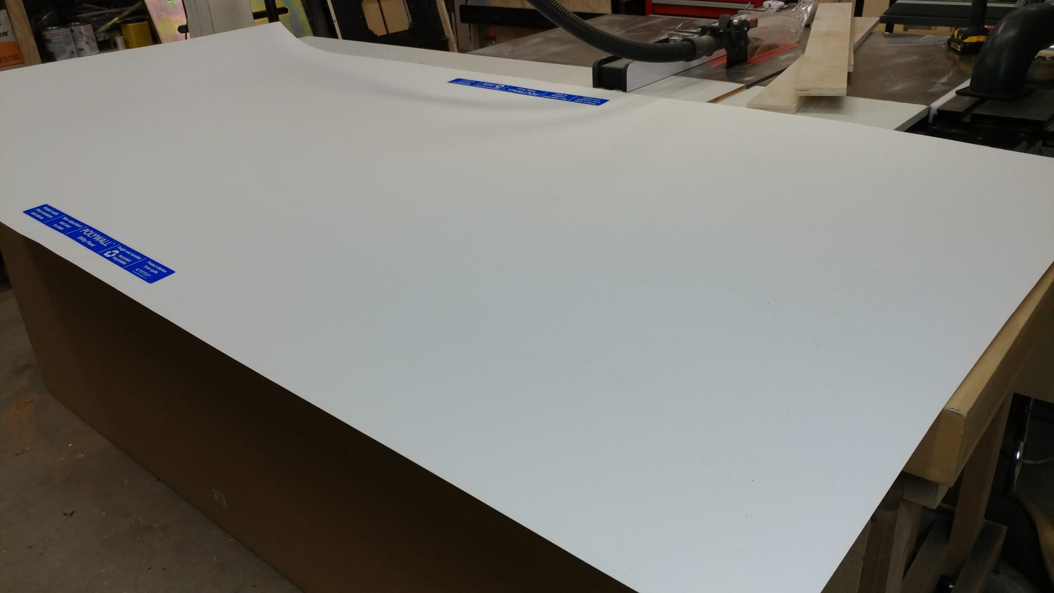
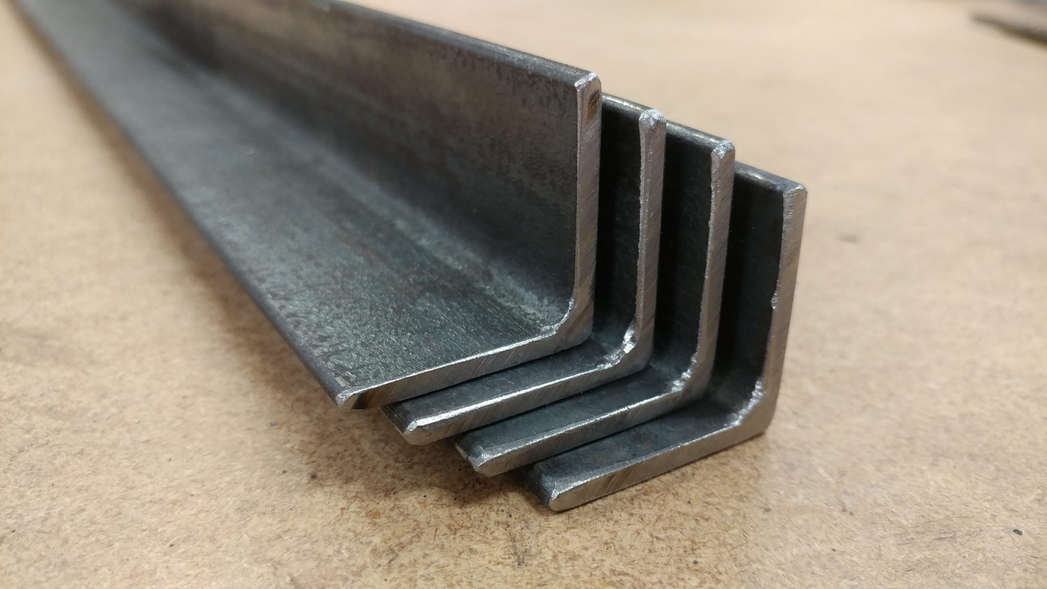
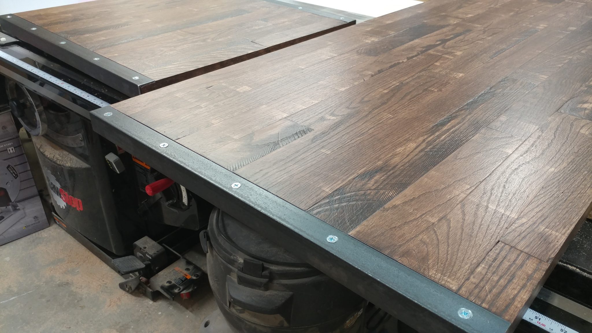
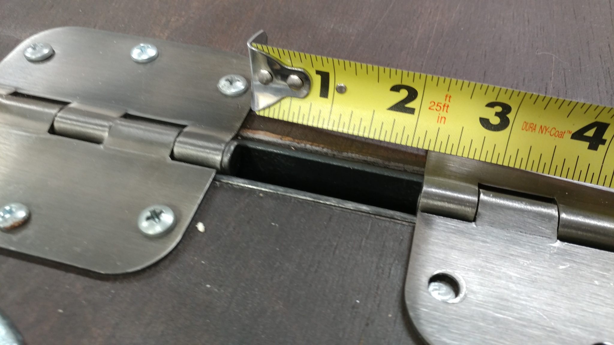
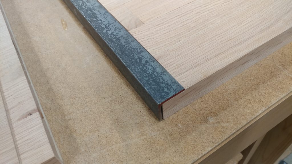
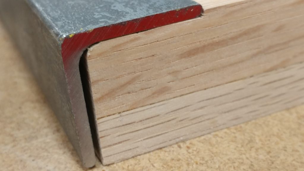
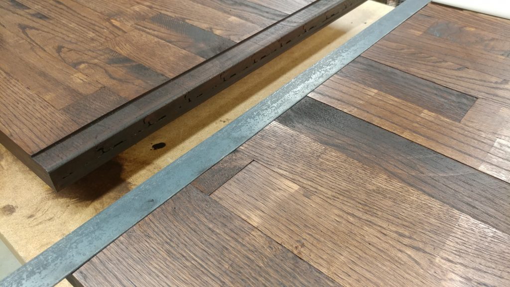
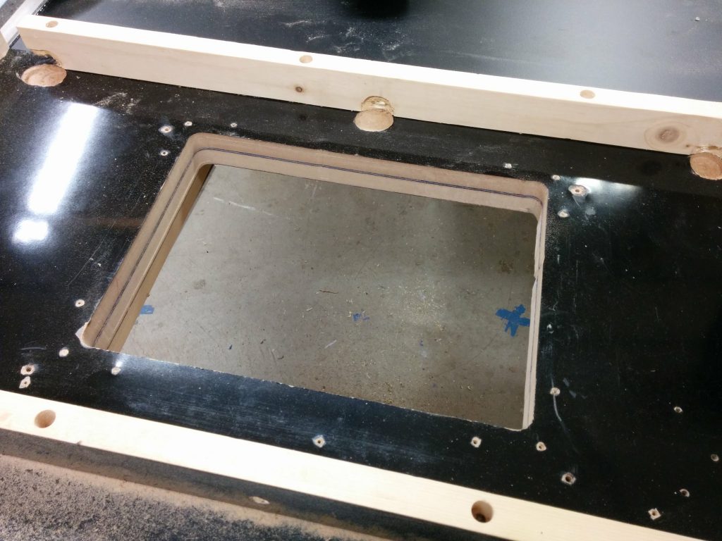
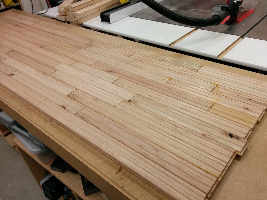
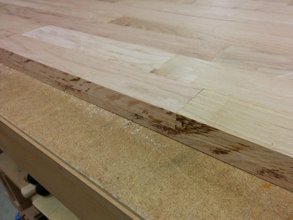
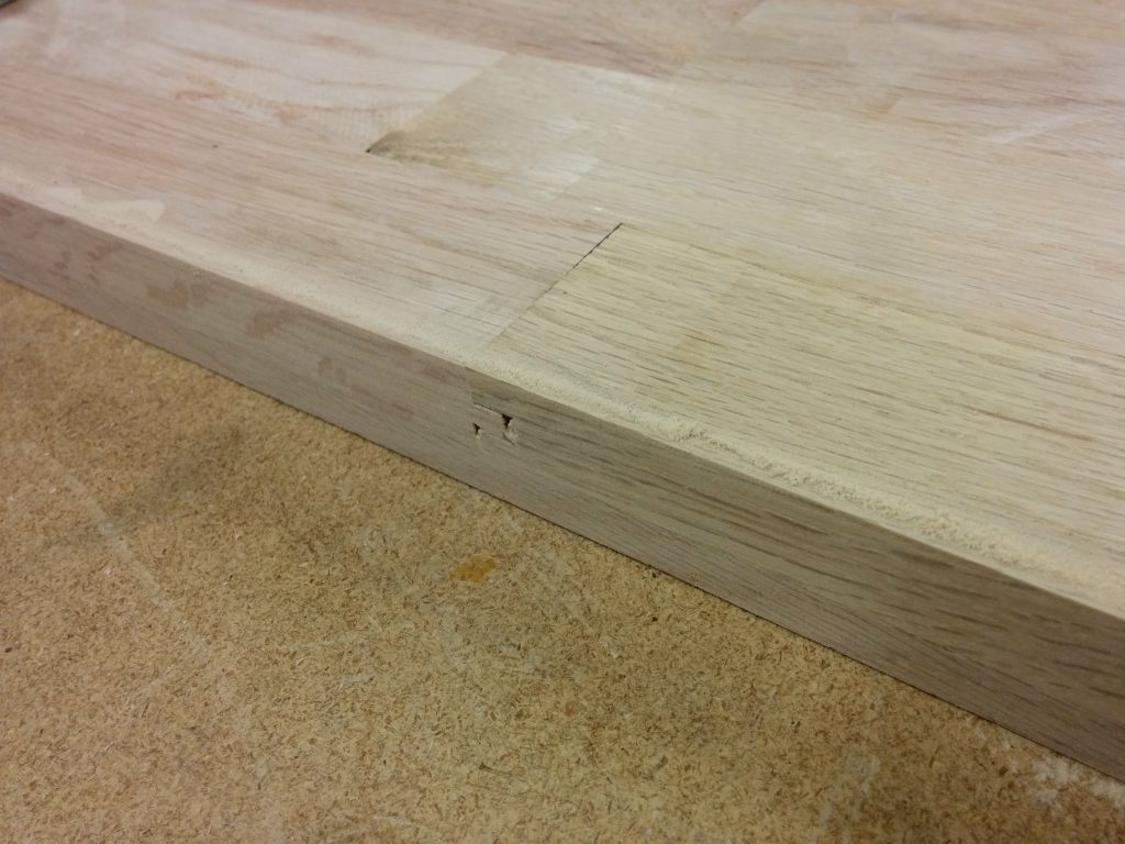
Attaching the angle iron to the ends of each piece.


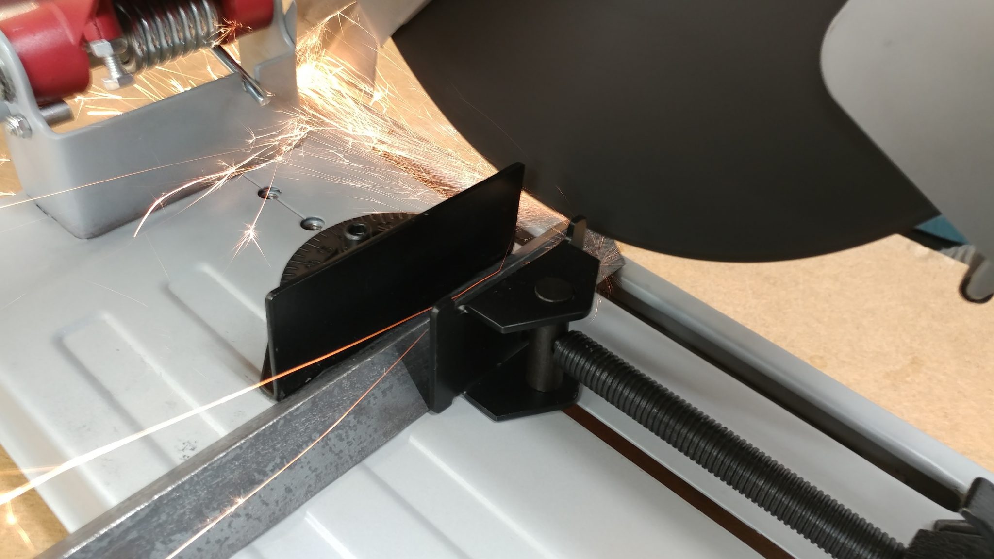
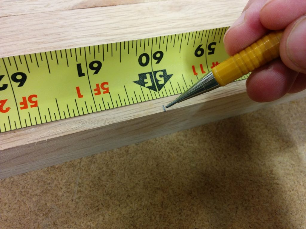
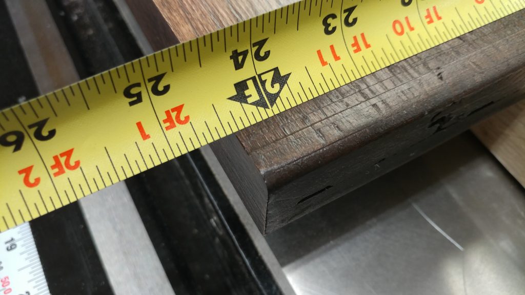
The bench-top is 23-7/16″ deep so I need to cut four pieces of angle iron to that length.

The final depth of the benchtop is 24-7/16".


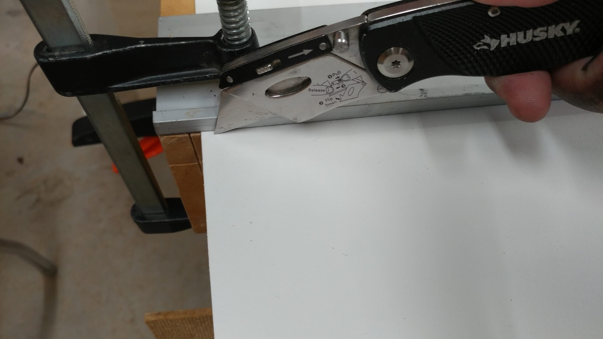
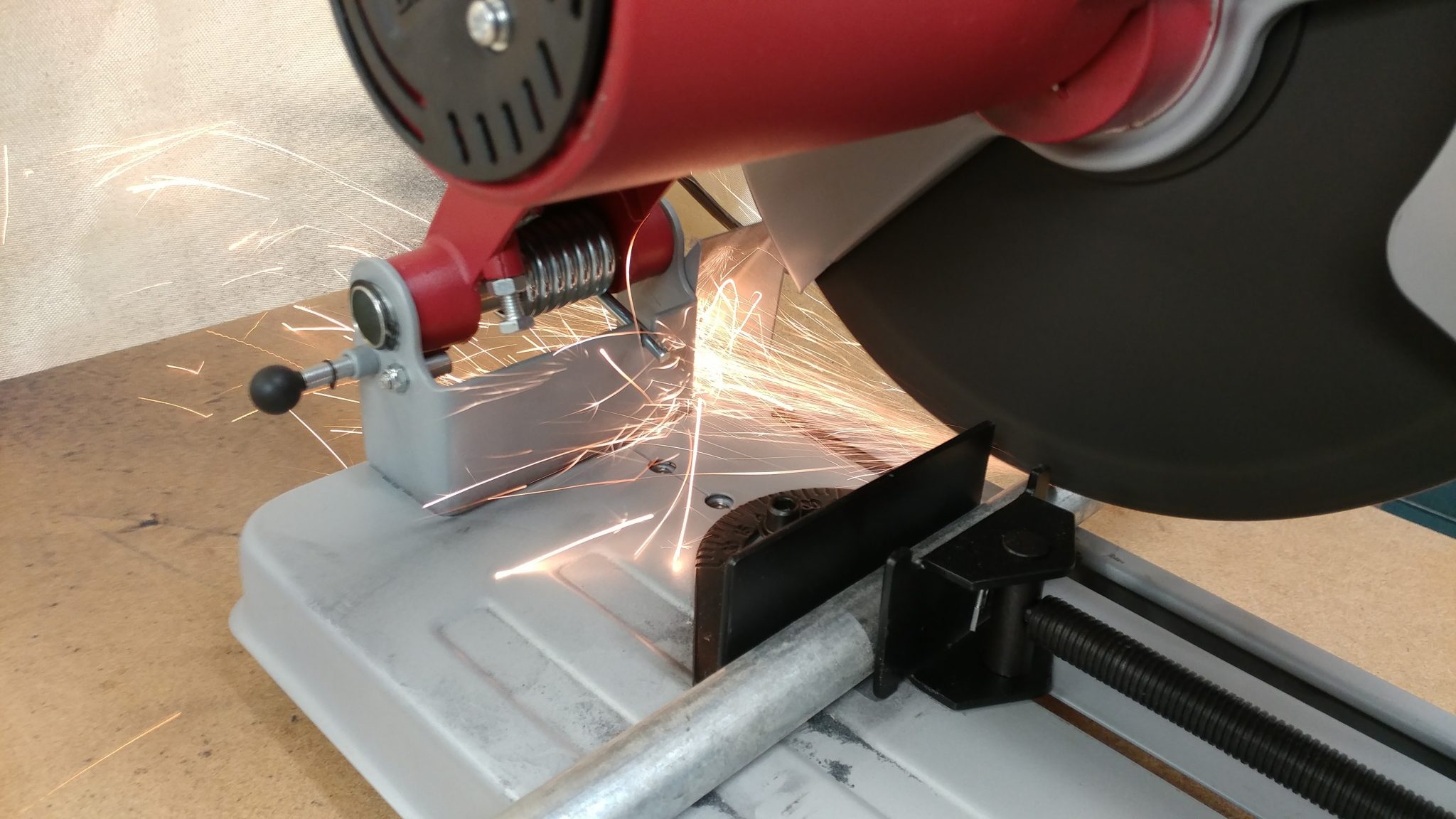
A metal chop saw was used to make all my cuts but you can do this with a hacksaw if you don’t mind the blisters and carpal tunnel.

A metal chop saw made this process go pretty quickly.


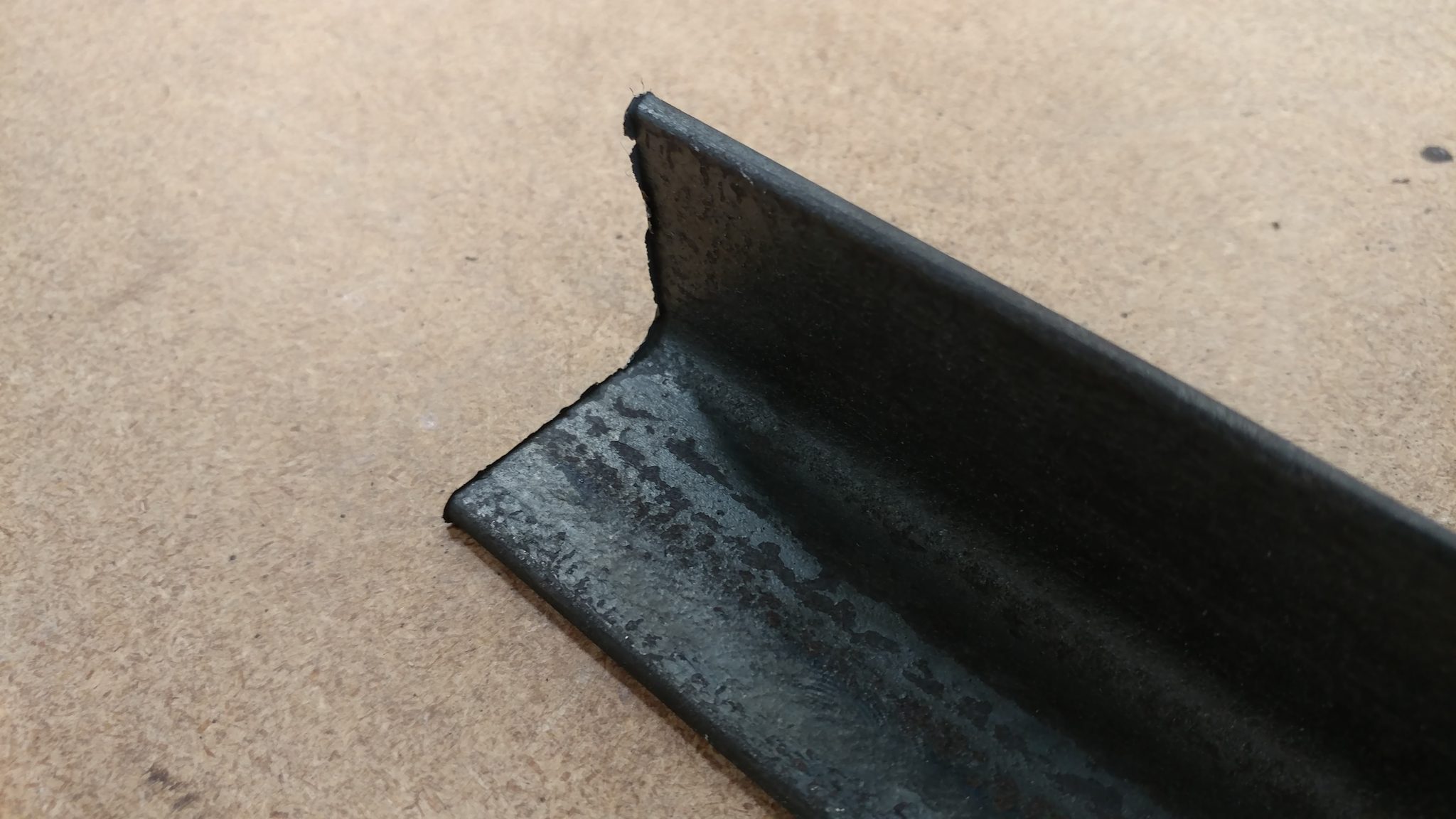
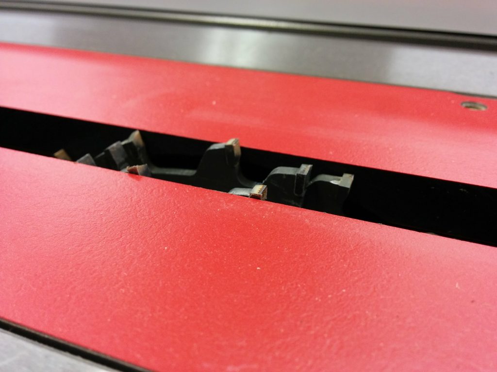
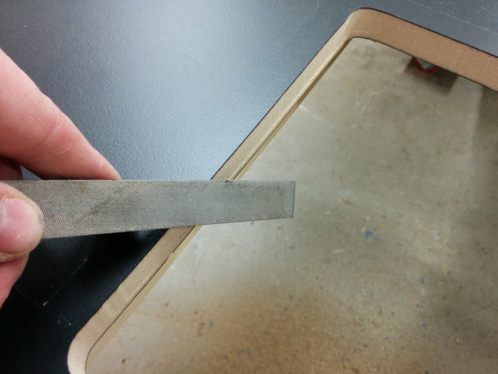
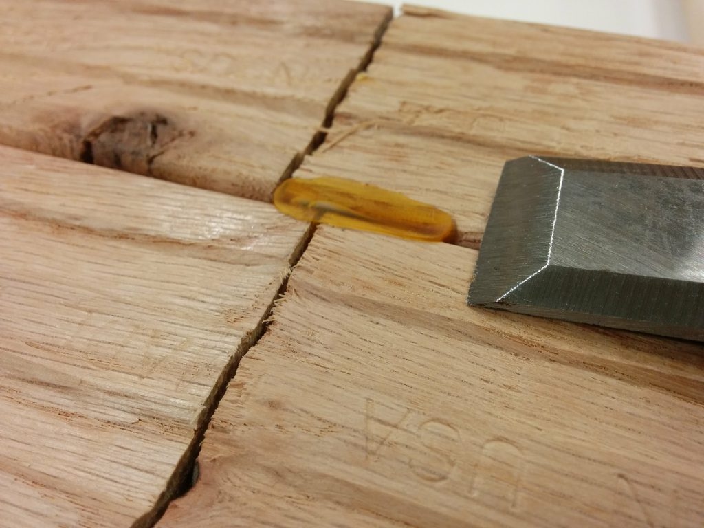
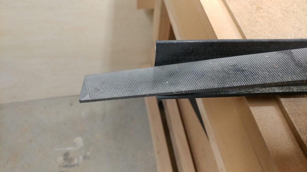
The chop saw leaves a jagged burr on the edge of the angle iron so I’ll need to knock that back.

Cutting on the chop saw left a pretty nasty burr that I needed to get rid of.


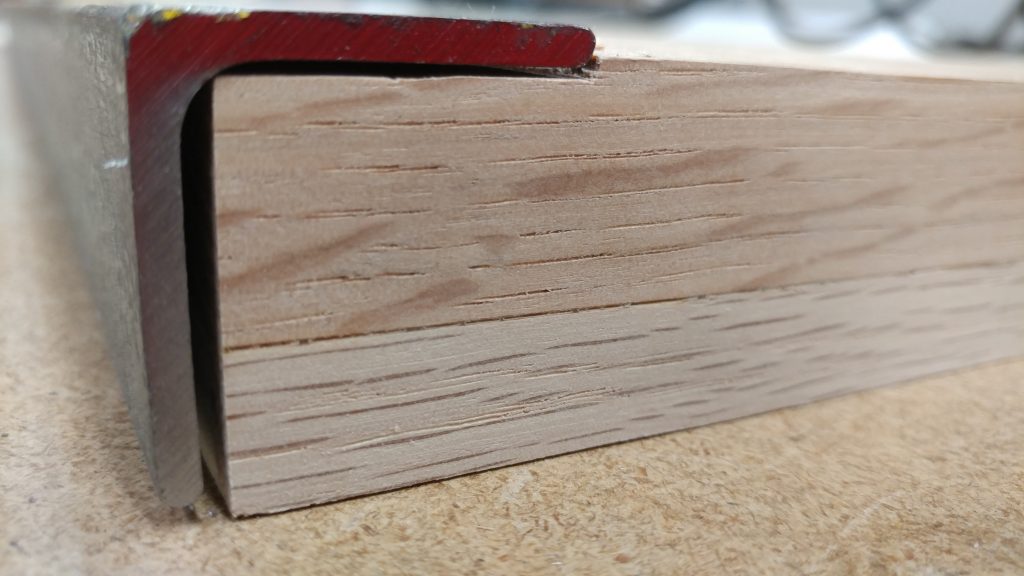
You can use a hand file to remove most of the burr from each end of the pieces of angle iron.  I did this while slightly rounding over the ends.

I used a metal file to get rid of most of the burr.


To remove the burr on the inner corner I needed to use a rat-tail file.

A rat-tail file was used to knock back the burr on the inside corner.

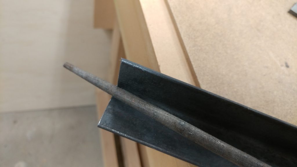
The burrs were removed from both ends of each piece of angle iron.

Both ends of all four angle iron pieces have been filed and slightly rounded-over.


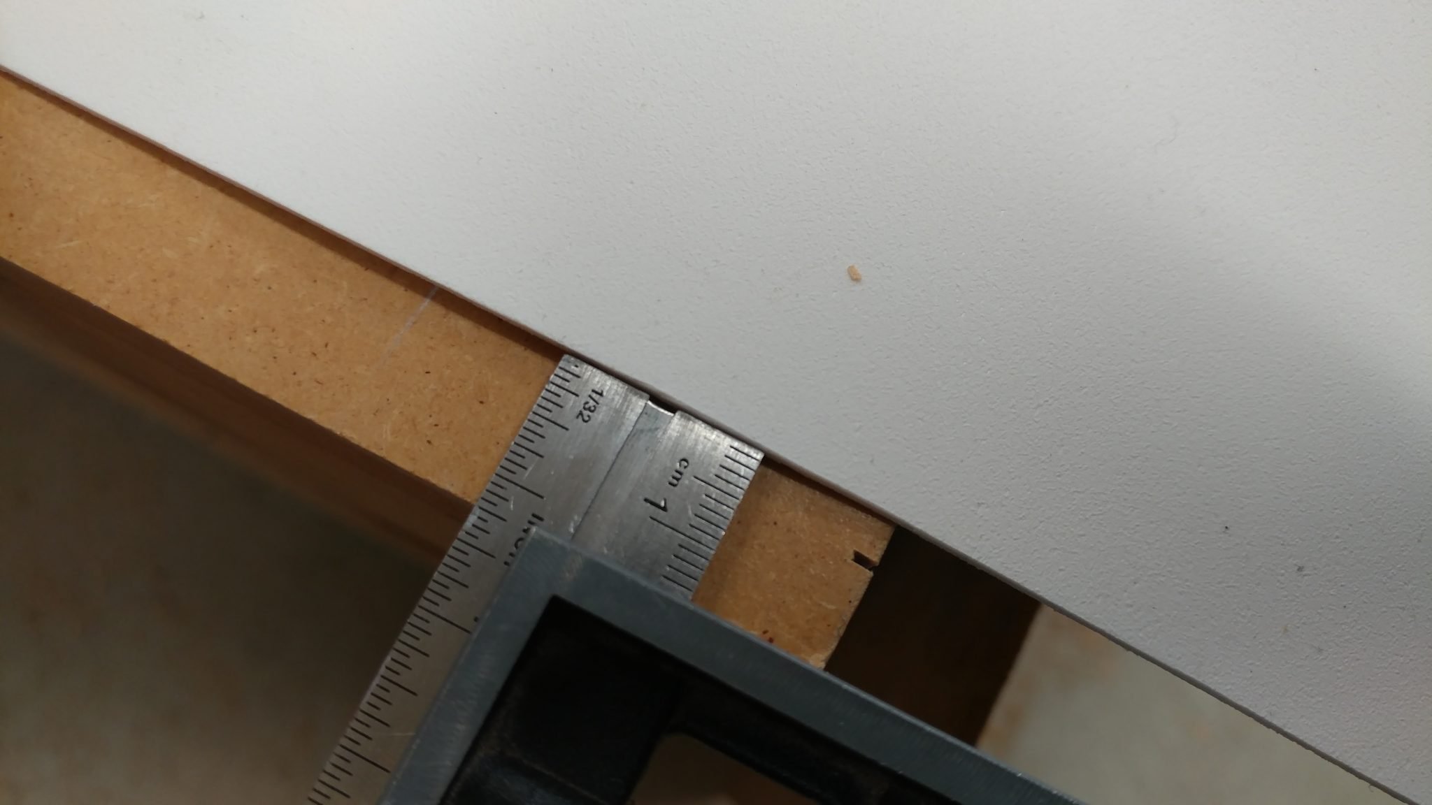
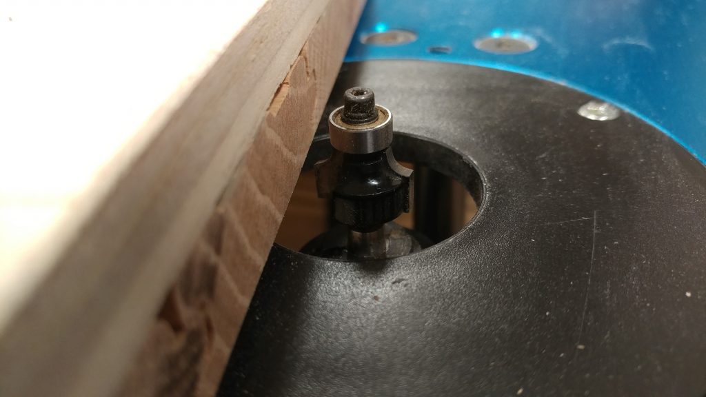
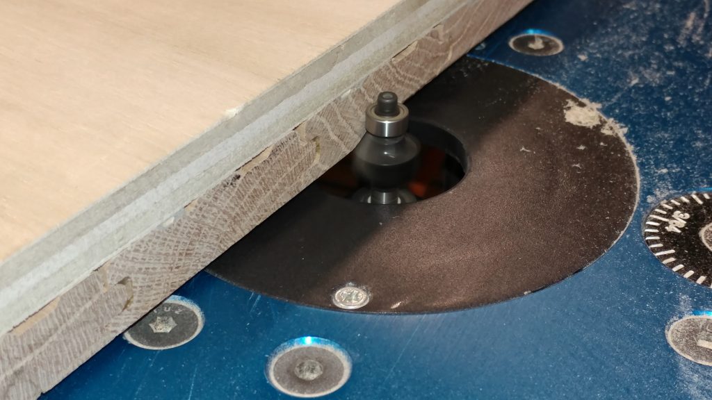
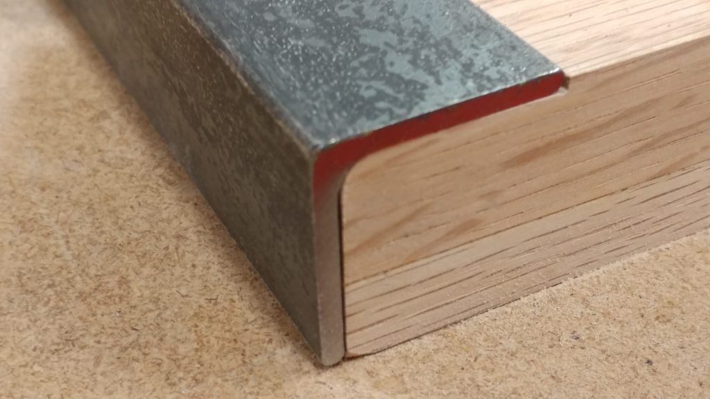
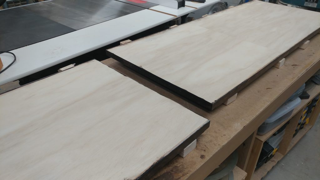
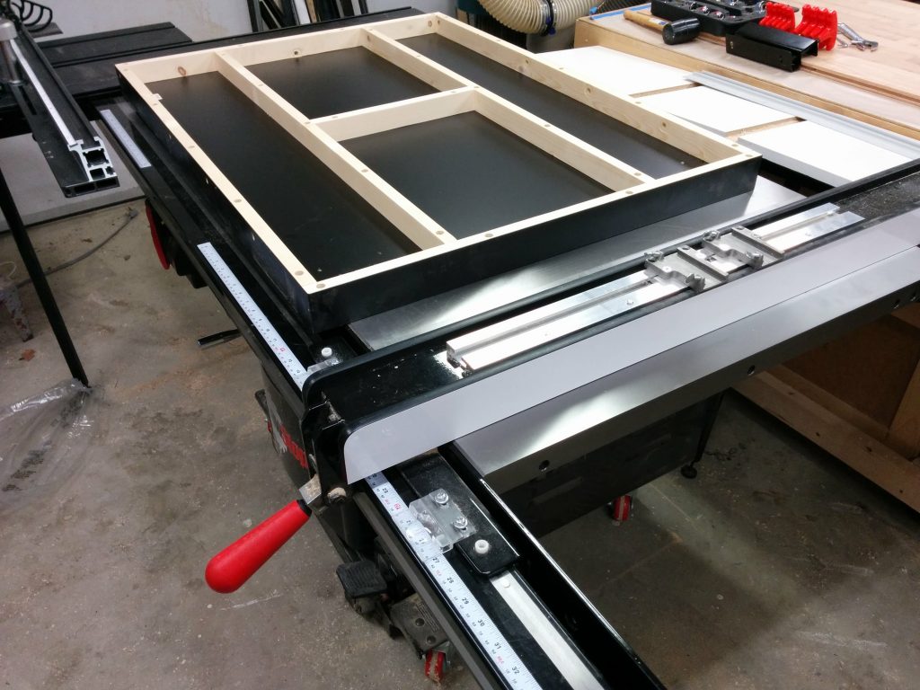
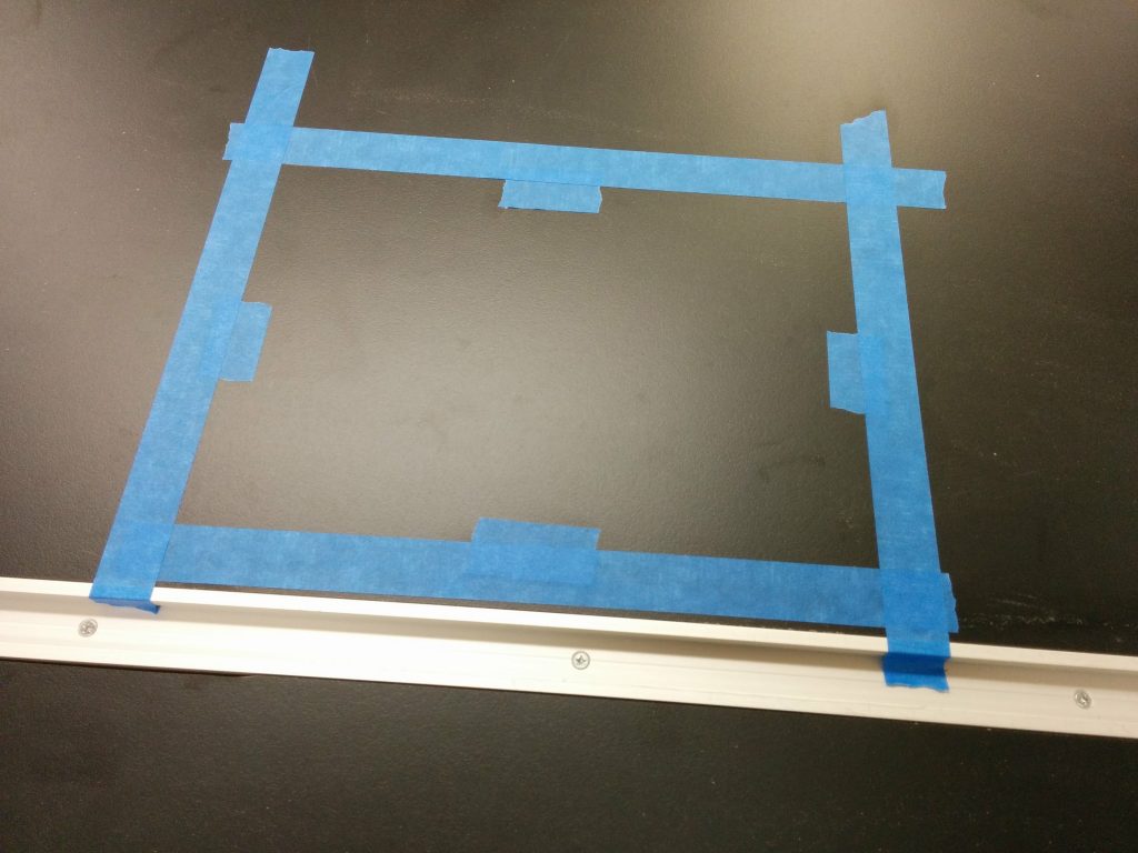
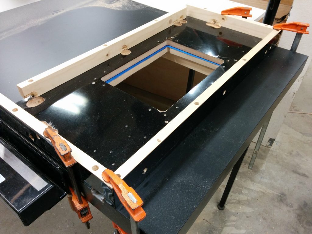
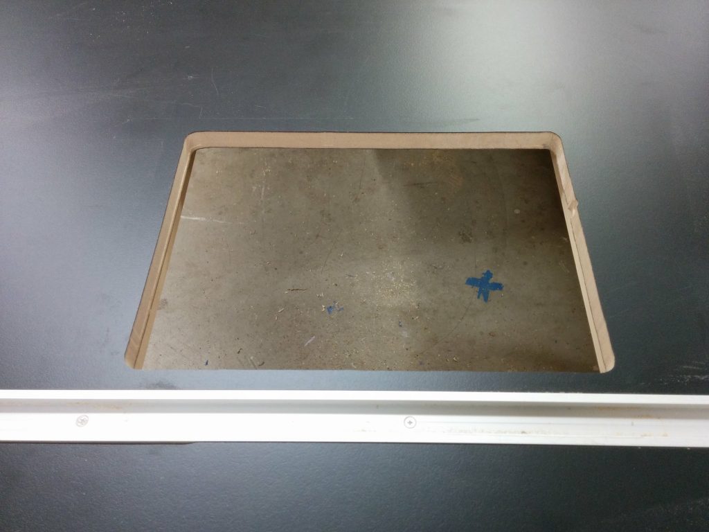
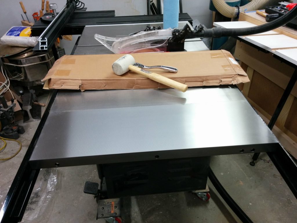
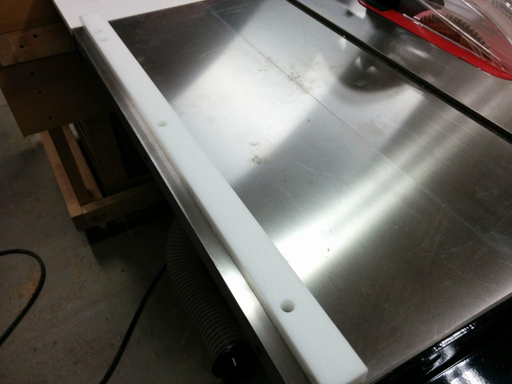
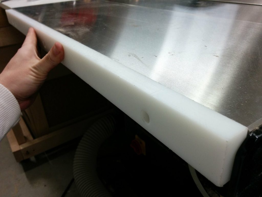
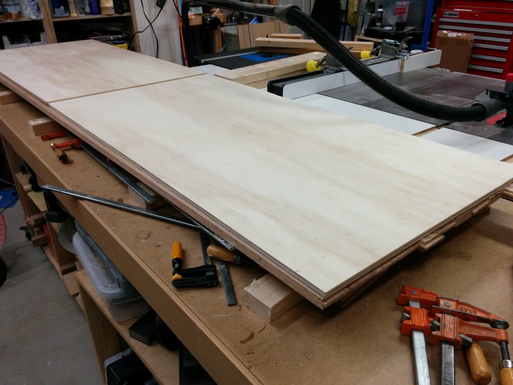
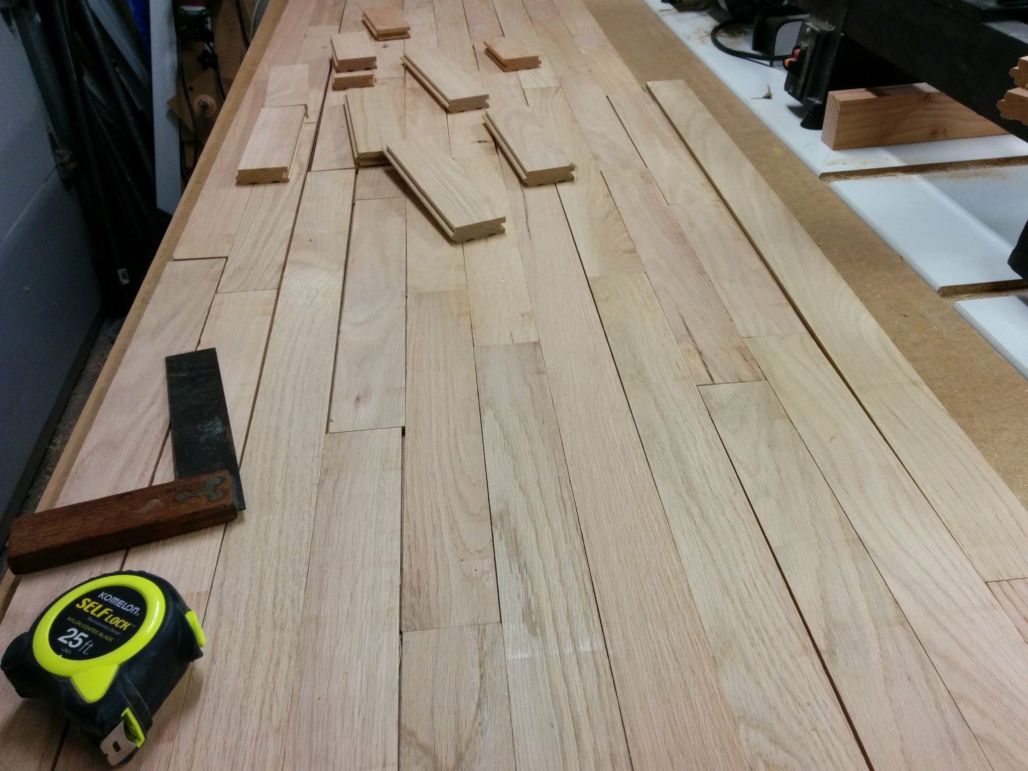
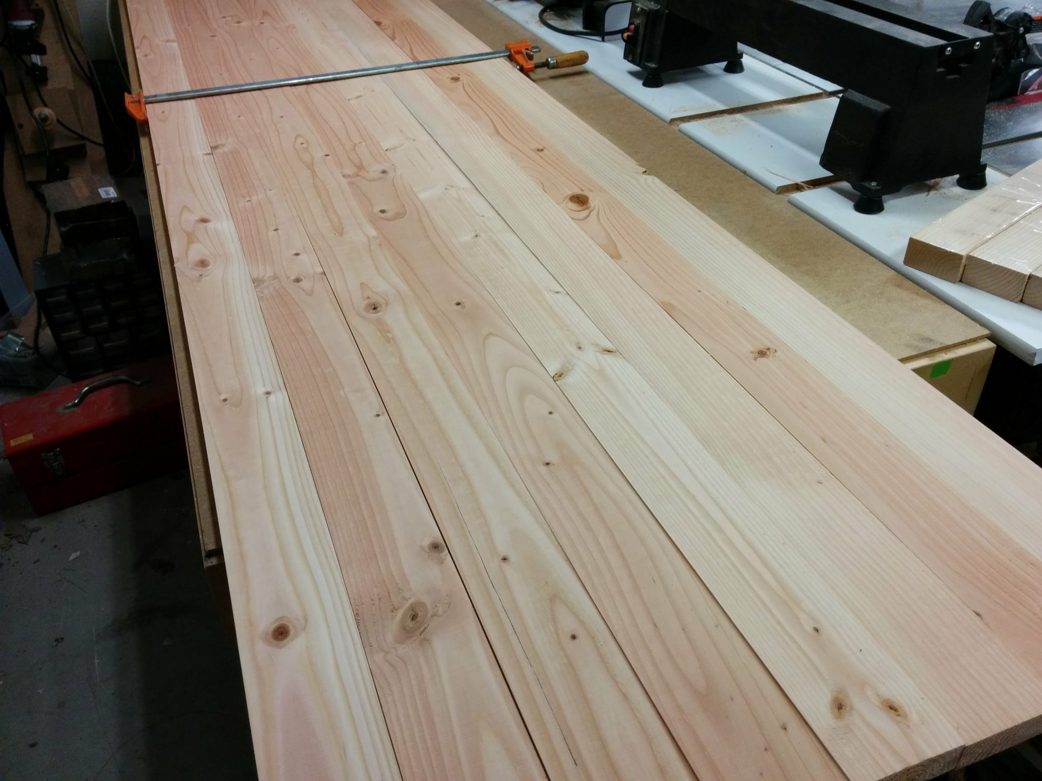
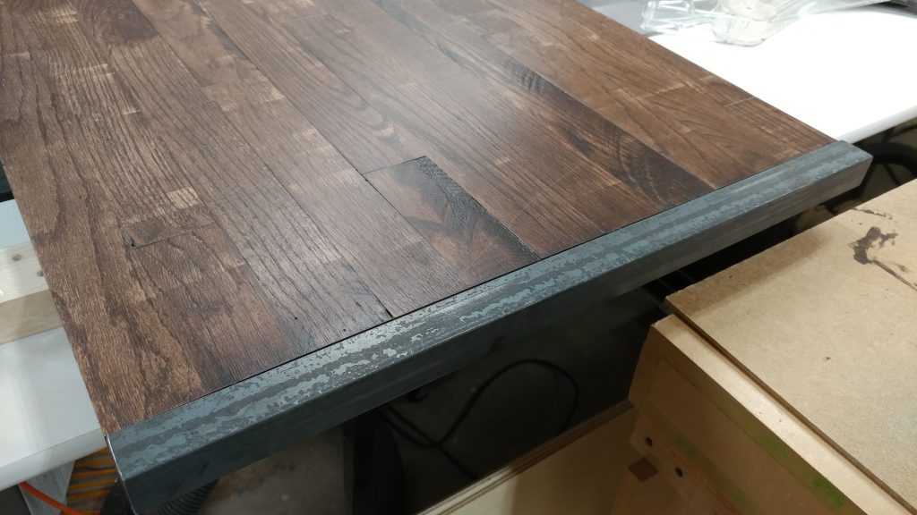
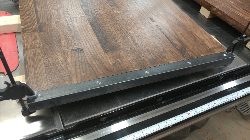
A test fit gives a preview of how it looks and lets you make sure that none of the metal pieces are too long.

A test fit shows that these pieces fit nicely.


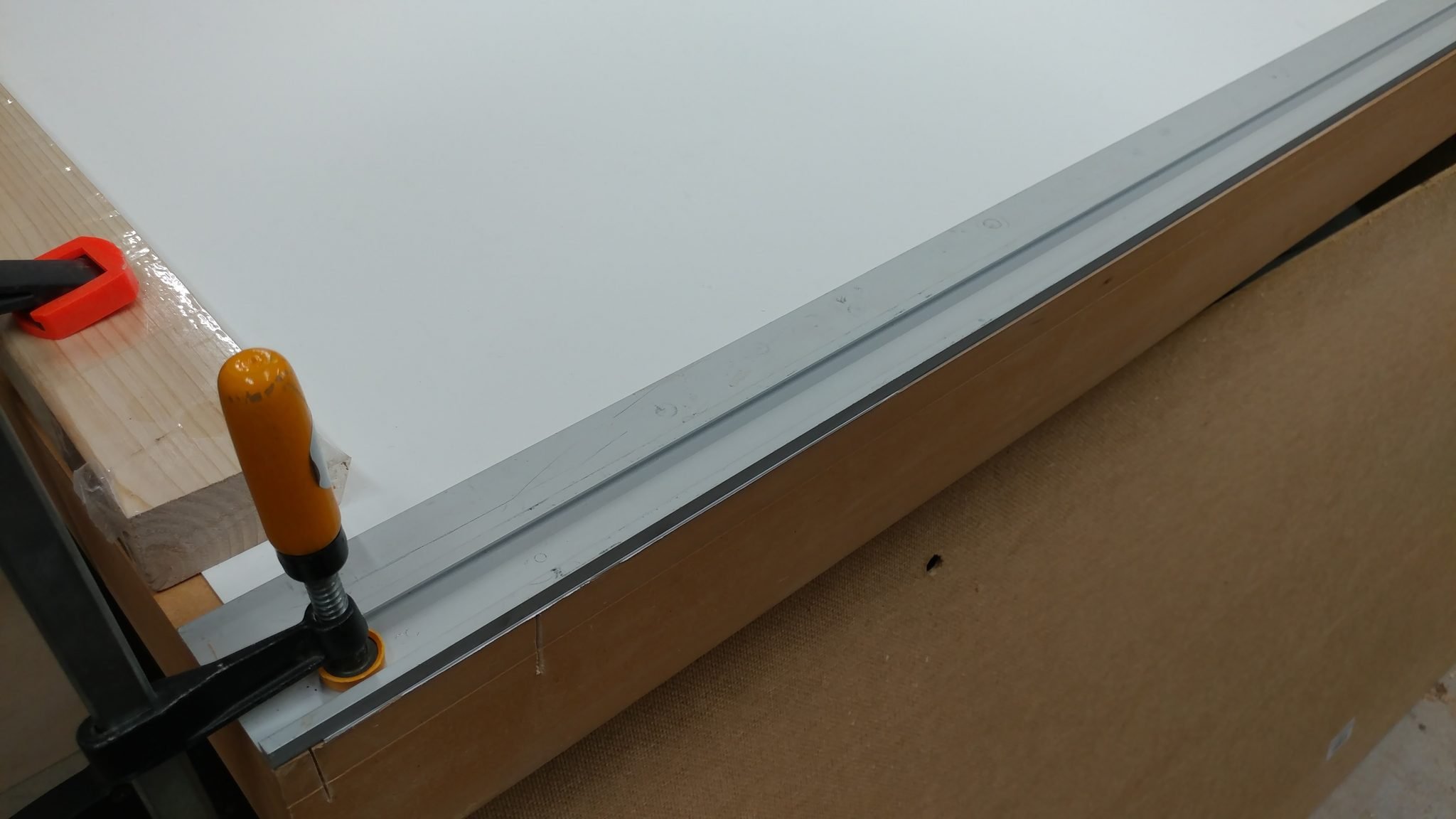
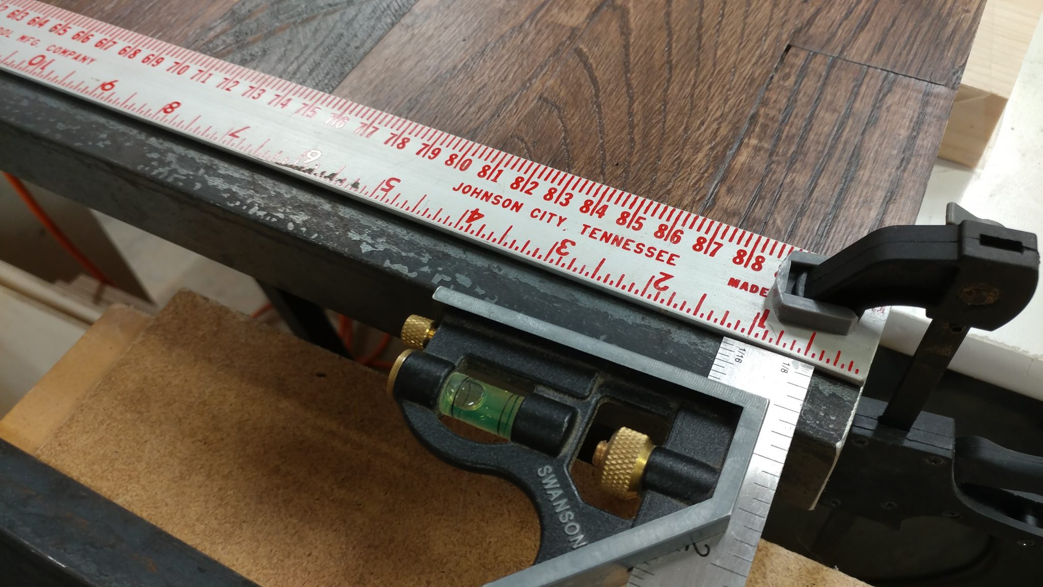
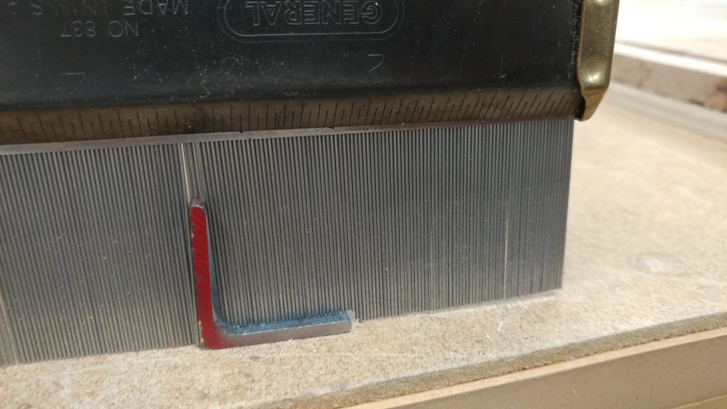
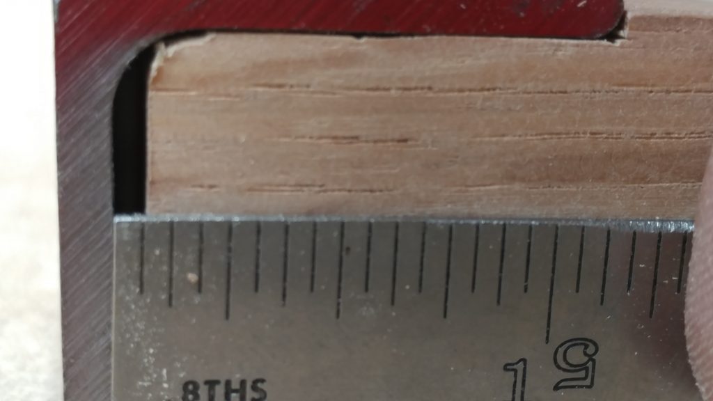
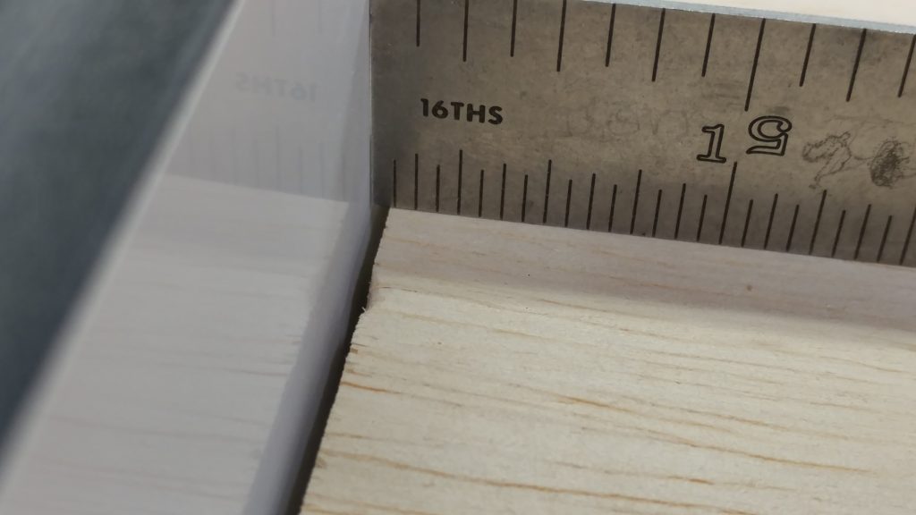
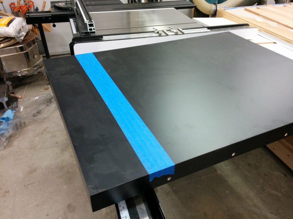
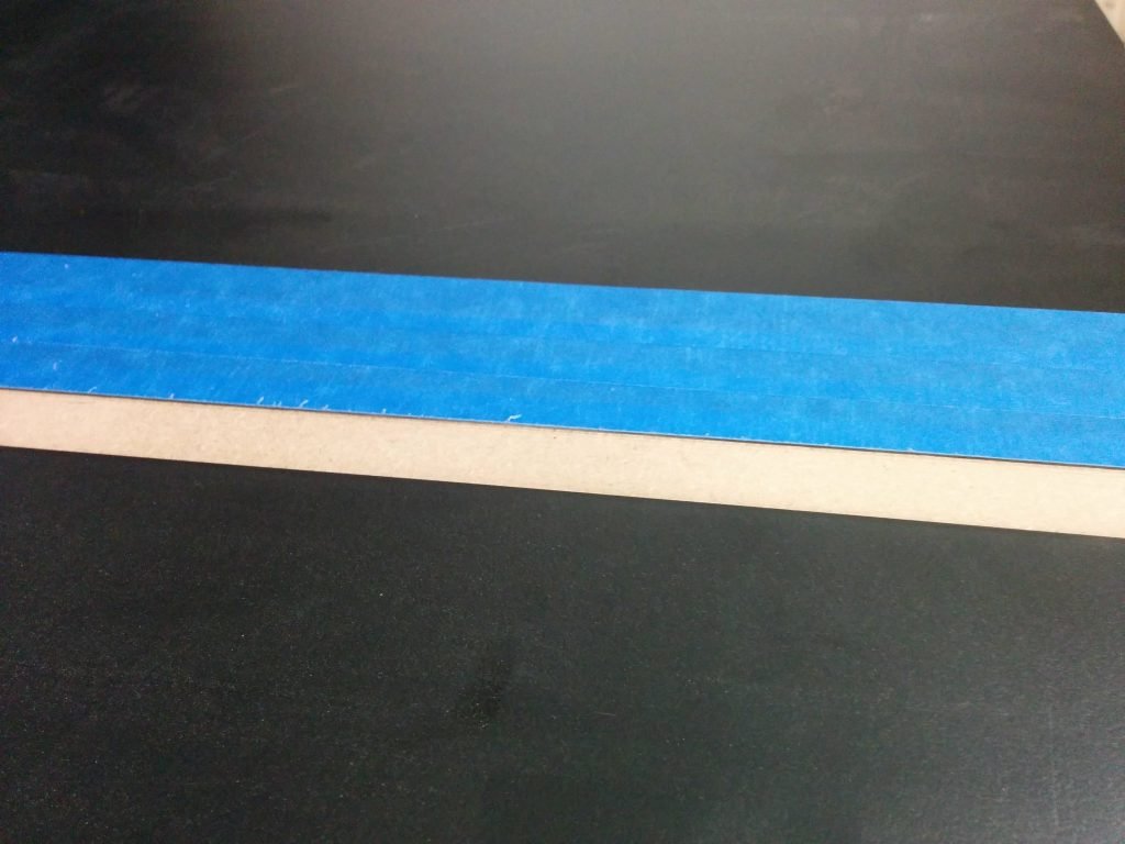
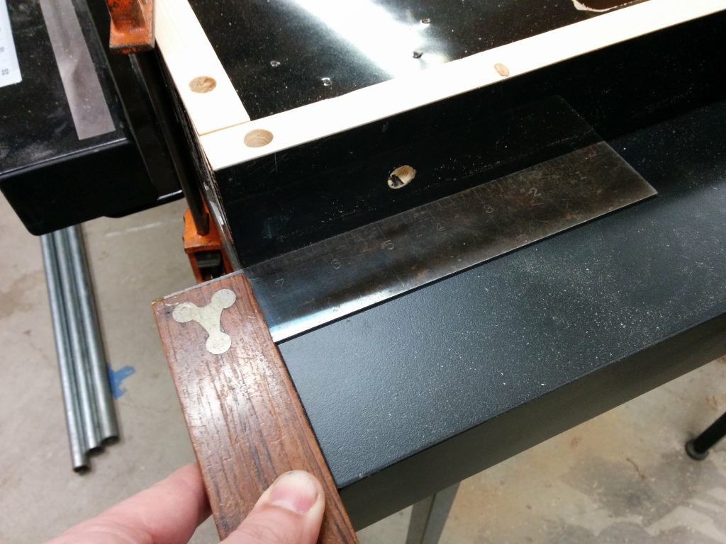
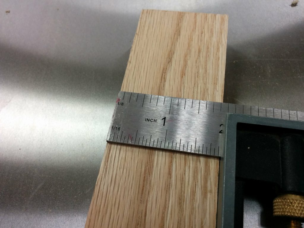
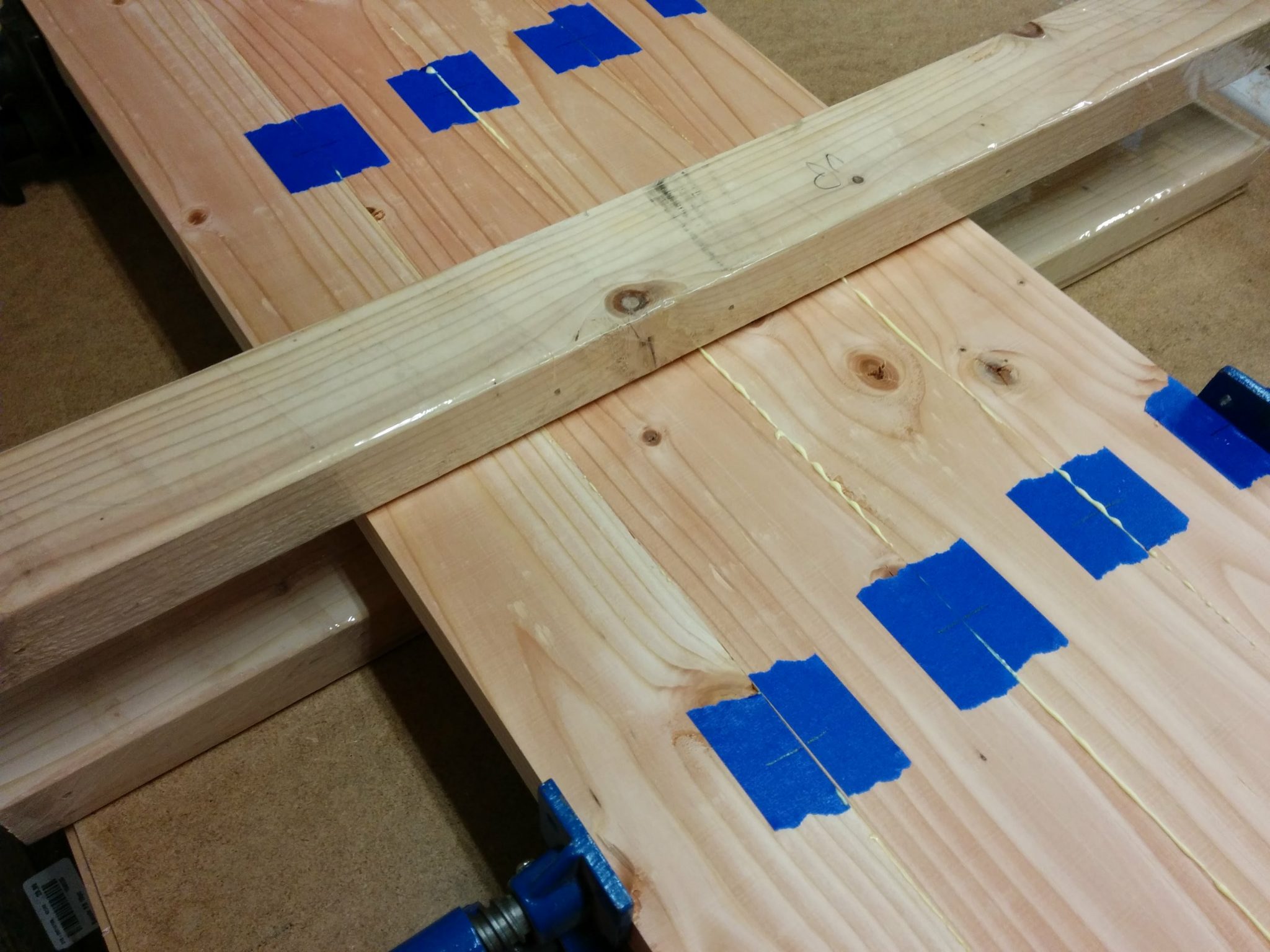
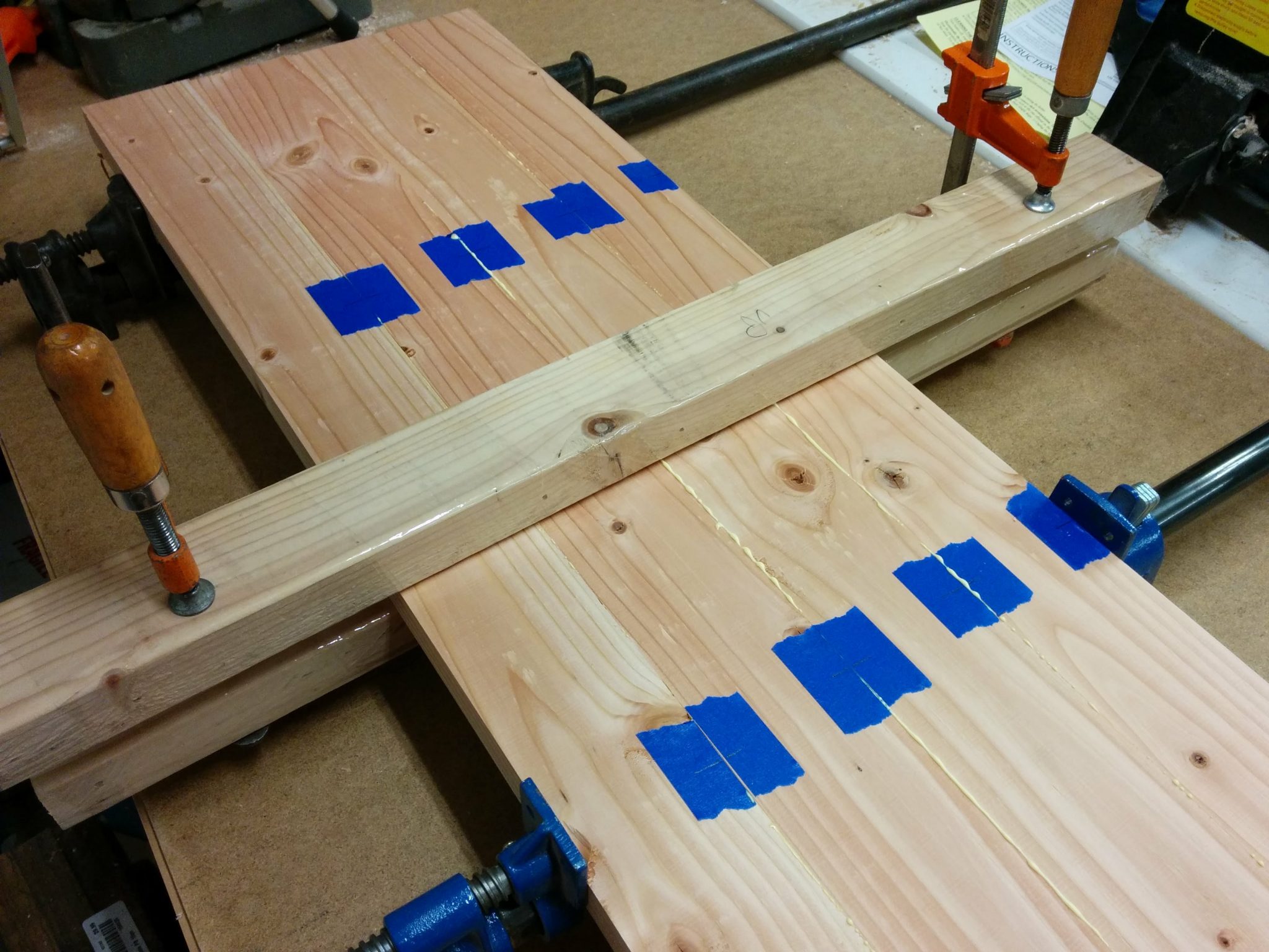
The screws will be attached in the center of the angle iron so I set my combination square to half the width which ended up being 5/8″.

I set my combination square to 5/8" which is half the depth of the angle iron.


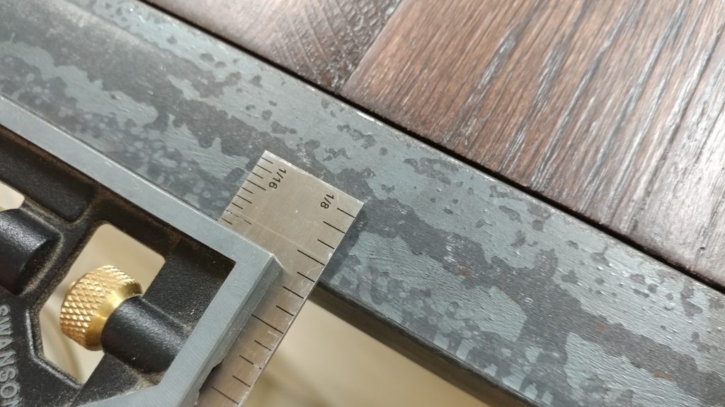
I used the combination square to set the position of a metal shop rule on the angle iron and I clamped it in place.

A straightedge clamped to the pieces at the correct depth made this process easy.


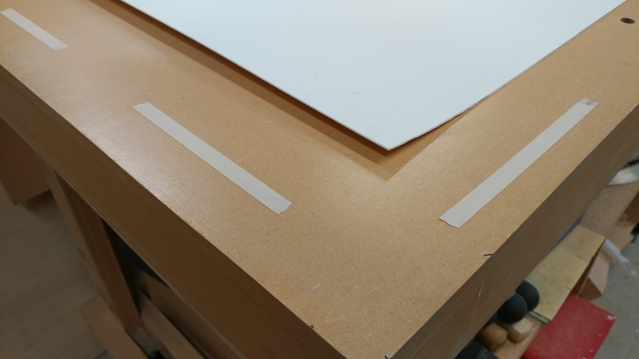
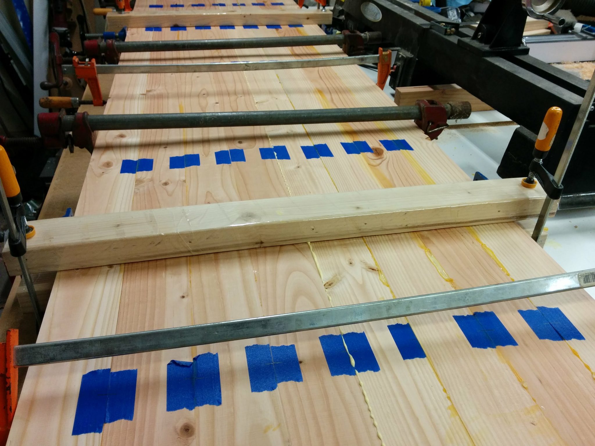
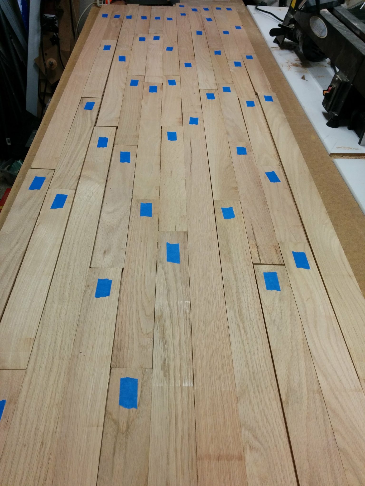
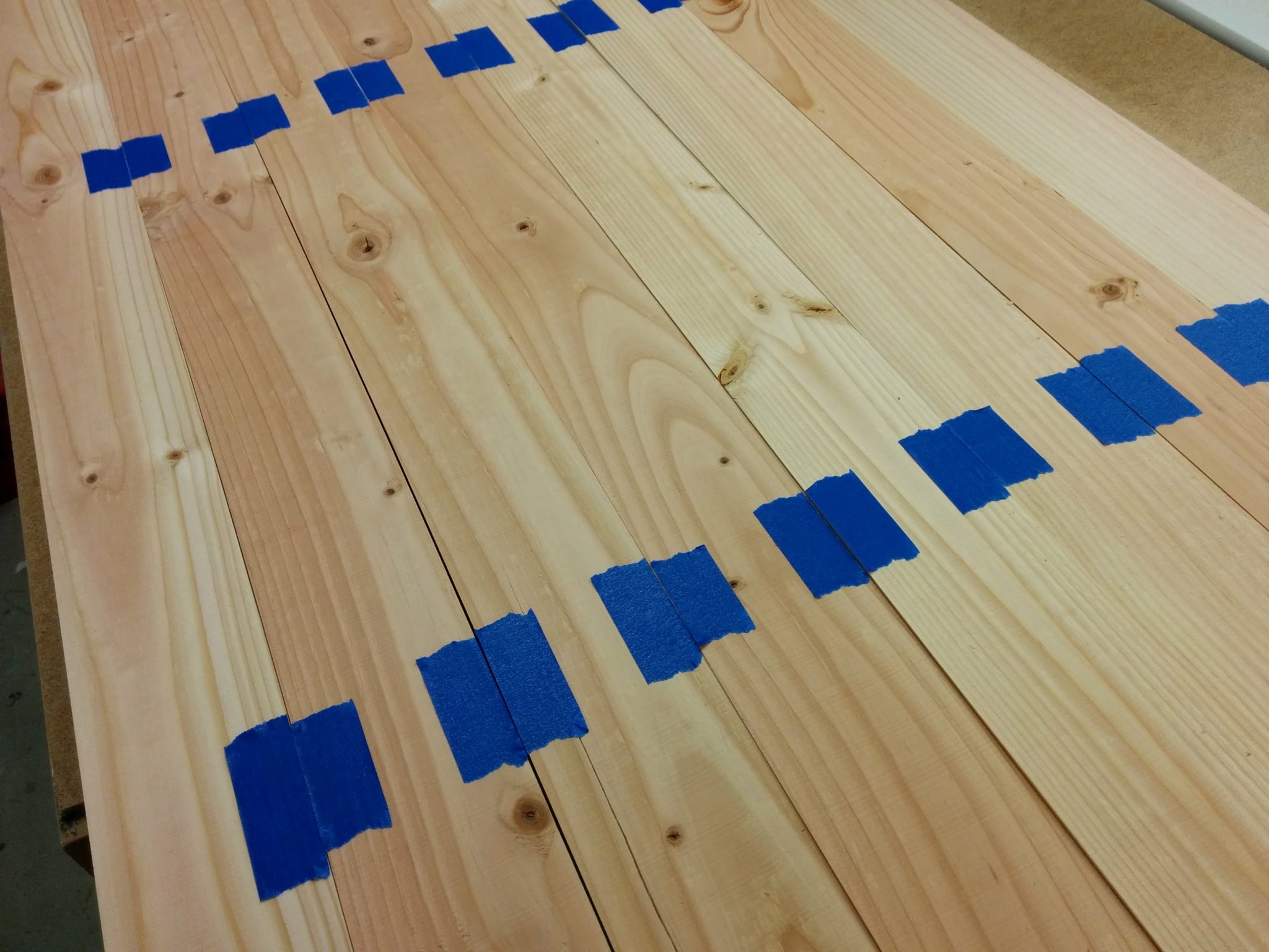
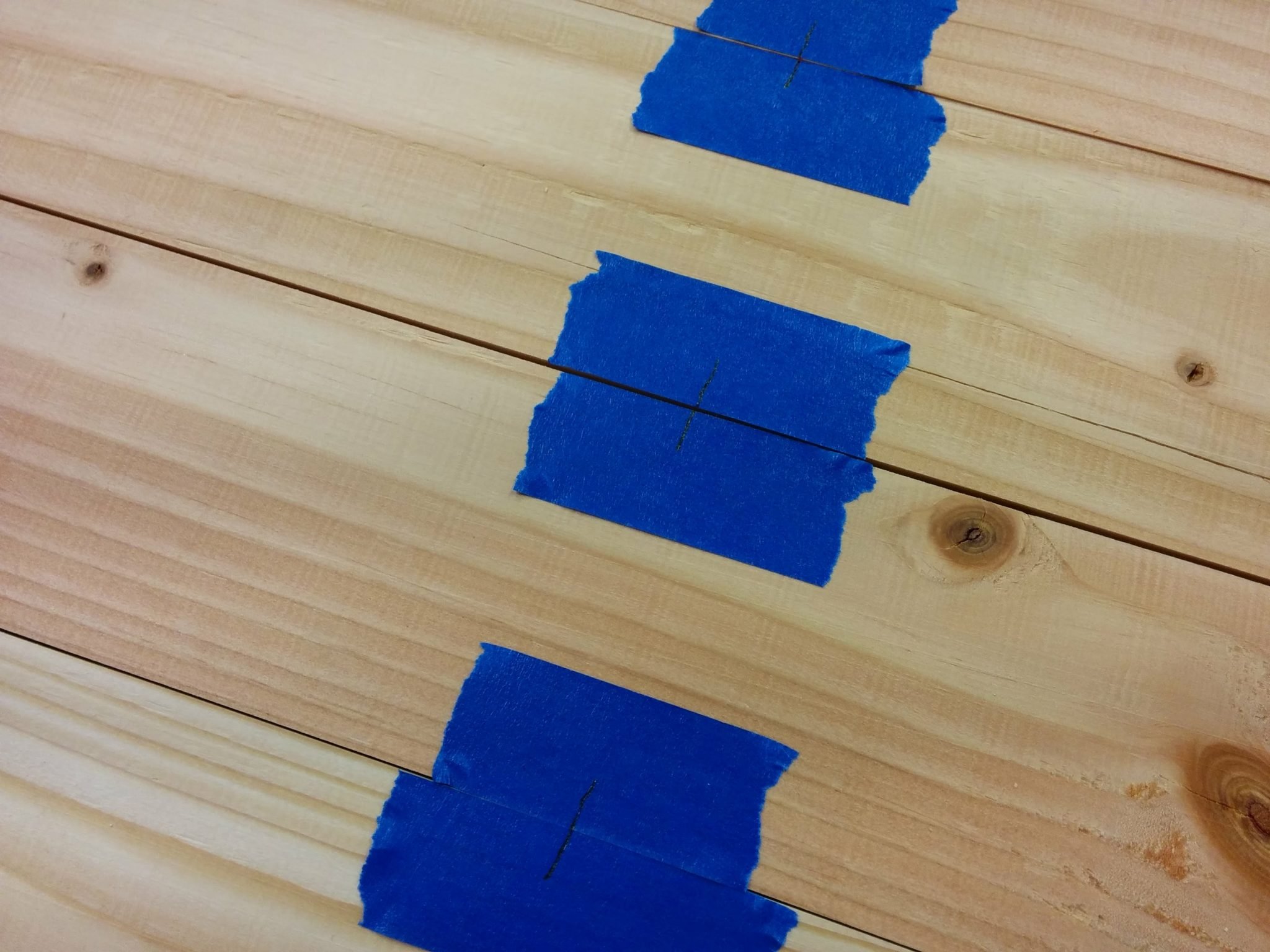
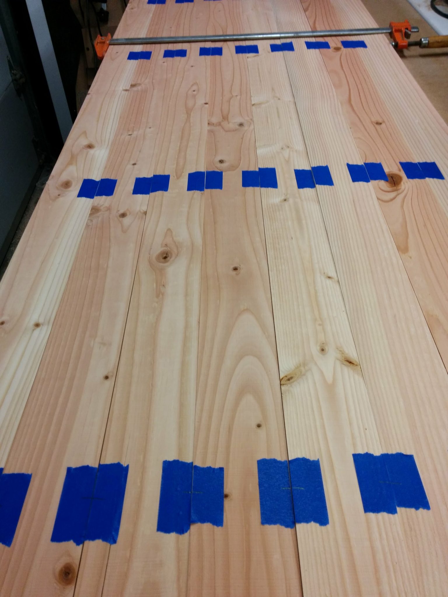
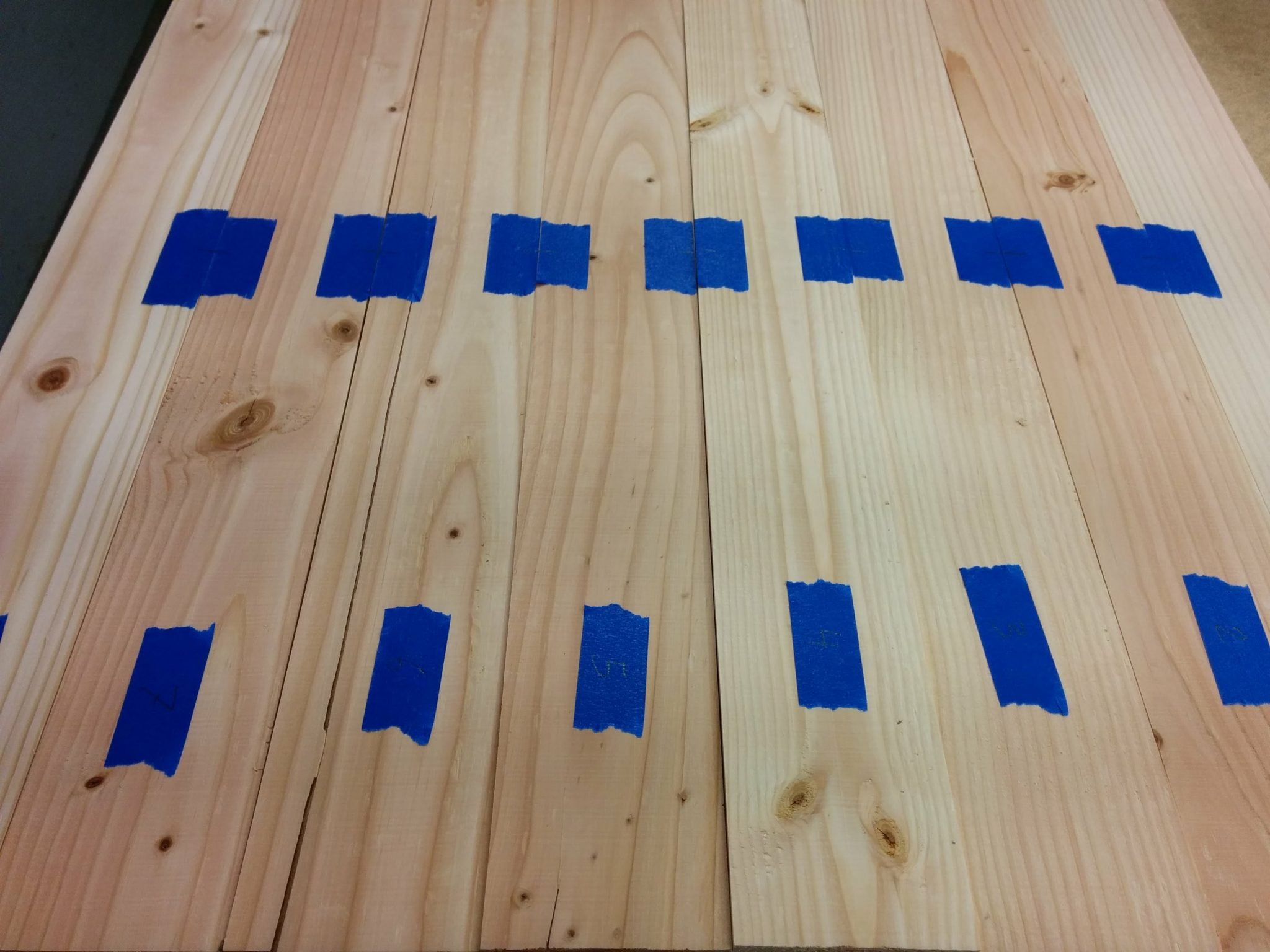
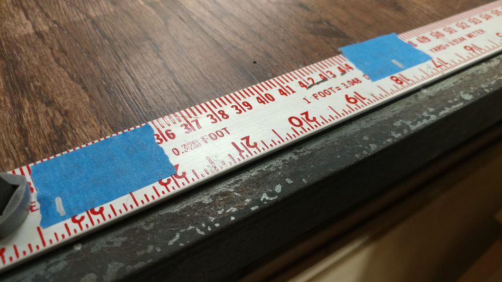
I decided on the placement of the screws by first marking where the center screw will be and then adding the marks for the outer screws about 1-1/4″ inches in from the edge.  I then found the center point between the outer marks and the central one.  I used a silver Sharpie to mark the placement of the screws with some hash marks on pieces of painters tape so I could repeat them on each piece.

I added painter's tape and made marks at the spots where I wanted to drill my holes.


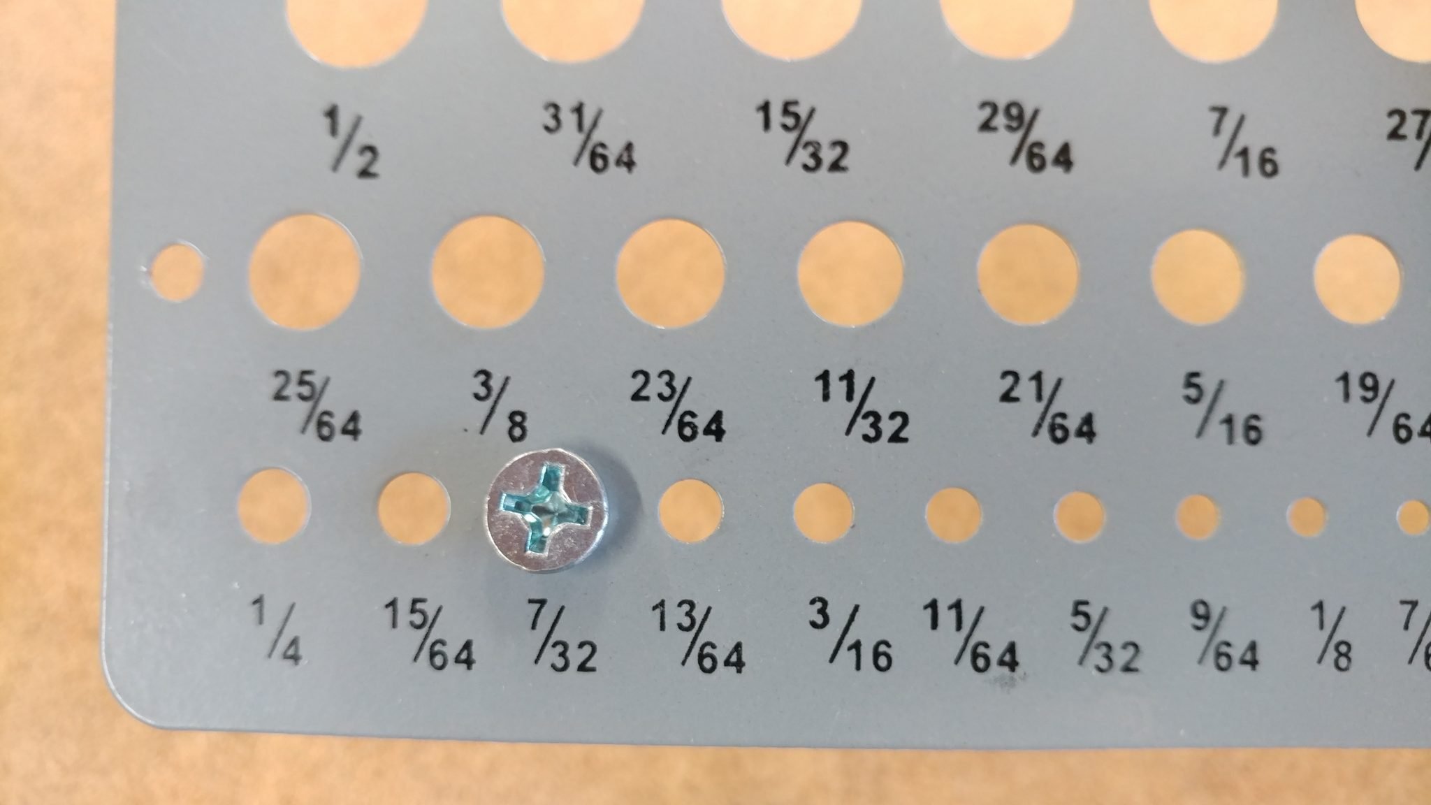
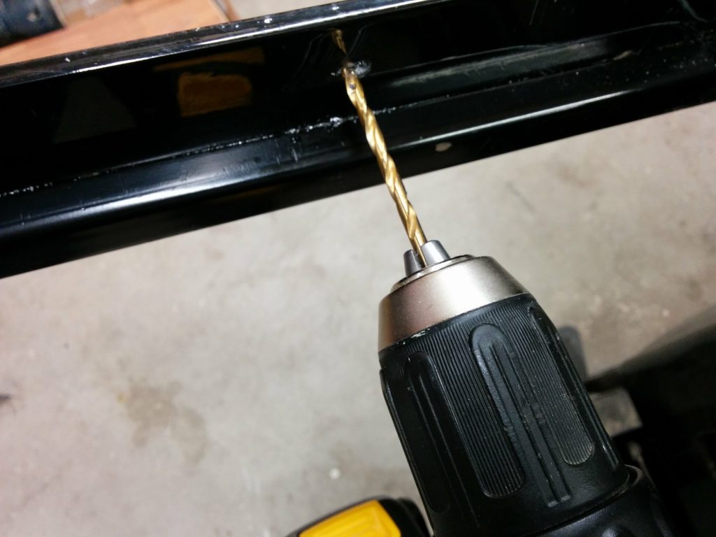
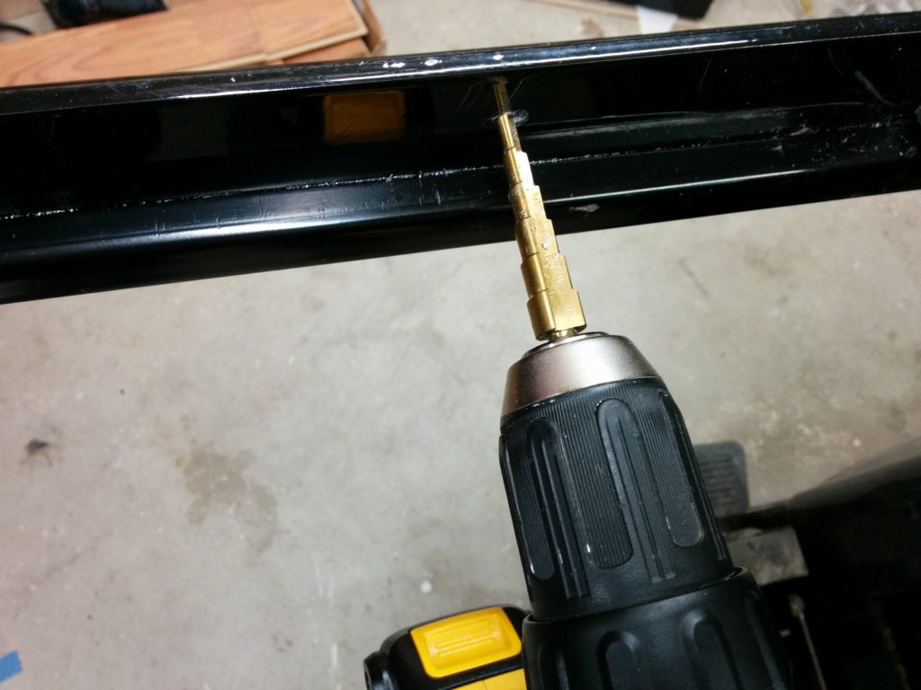
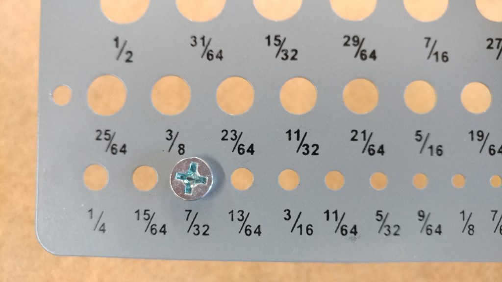
The screws that I am using to attach the metal require a 7/32″ hole.

The holes will need to be 7/32" in diameter in order to accommodate the screws.


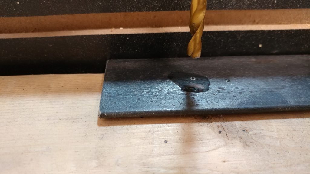
When drilling through metal you should usually apply a few drops of 3-in-1 oil to where you will be drilling out the holes.  This is what I did when I made the holes using a drill press.

I applied a few drops of 3-in-1 oil to the steel before drilling.


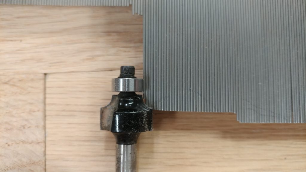
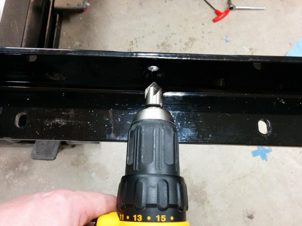
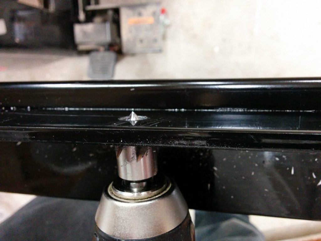
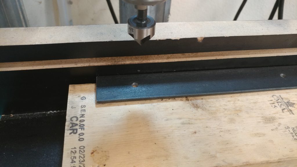
Since I wanted the screws to sit relatively flush with the top of the metal, I added a countersink to each hole using a 3/4″ countersink bit.  I went just deep enough for them to be flush but I didn’t want it too perfect since I’m going for a more used, industrial look.  Fortunately, making things “not perfect” is a specialty of mine.

I followed the 7/32" bit with a countersink so the screws sit flush.


This took quite a while. I ended up doing most of them with a hand drill which actually went much faster than the drill press and helped contribute to the imperfect look that I was going for.

All the holes are drilled and countersunk. You can see one screw inserted in one of the holes to test the fit.


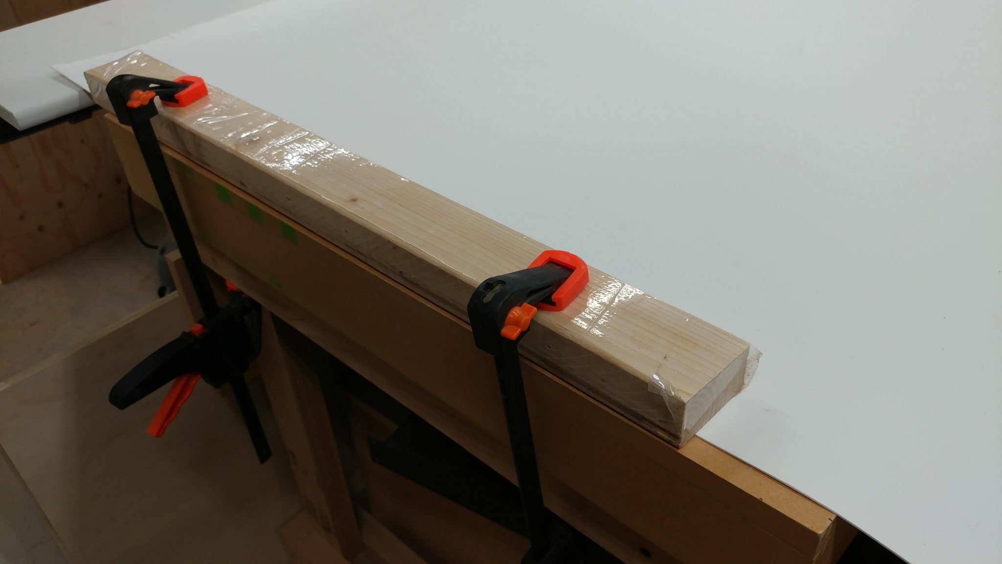
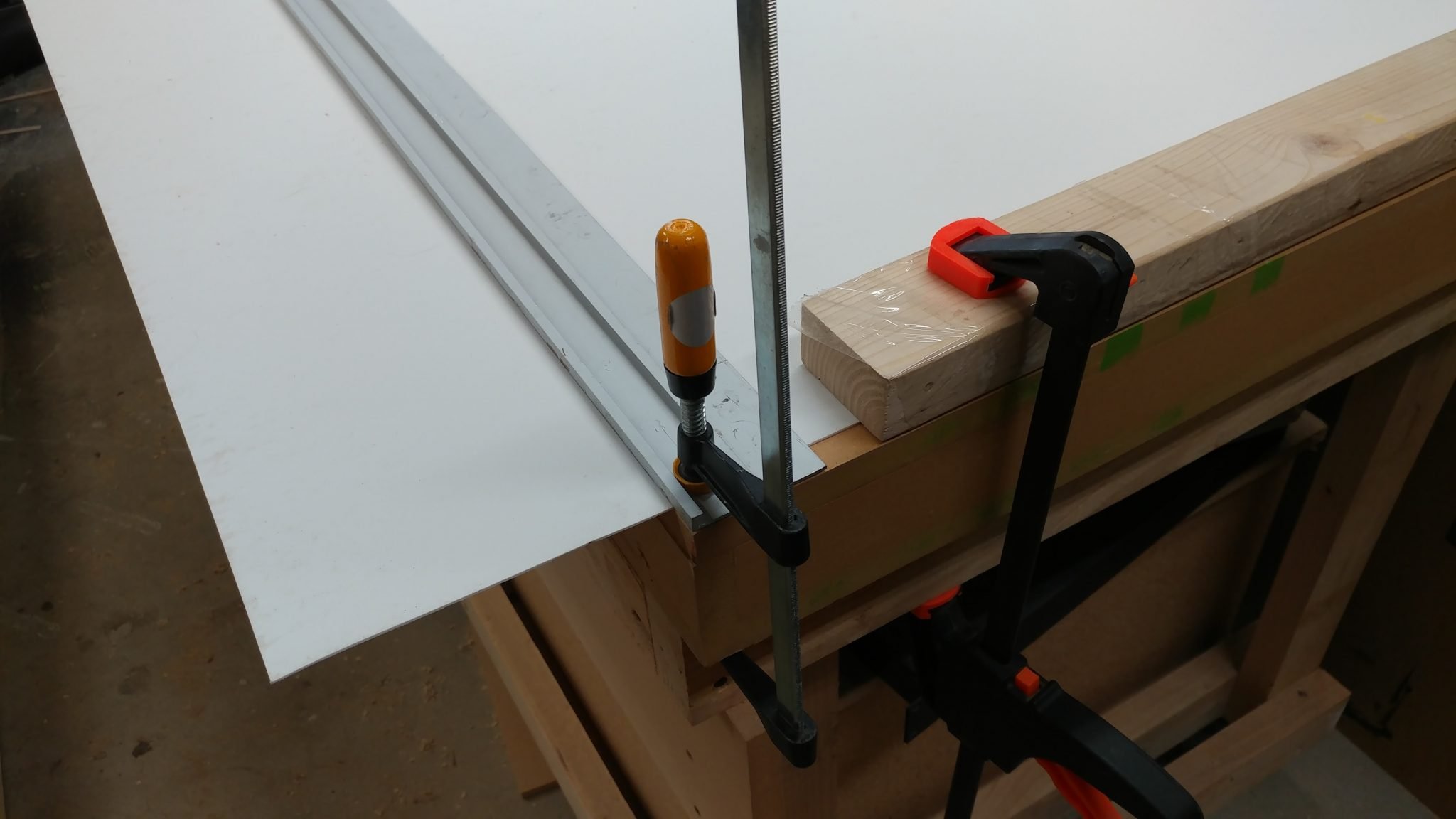
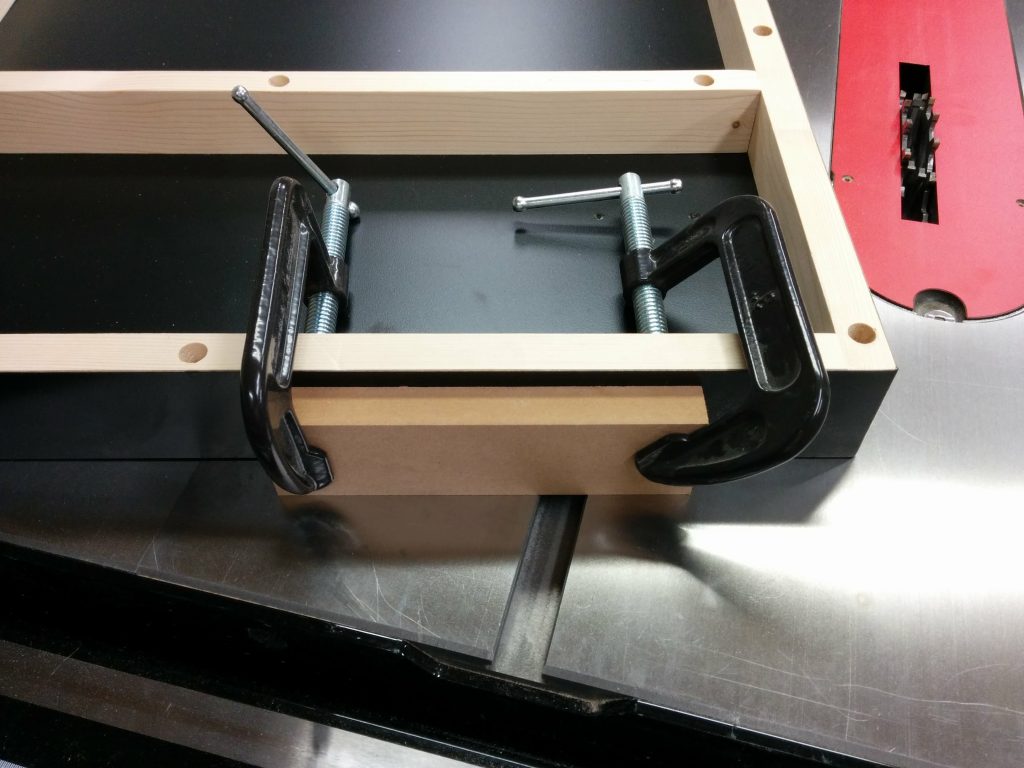
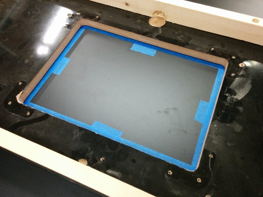
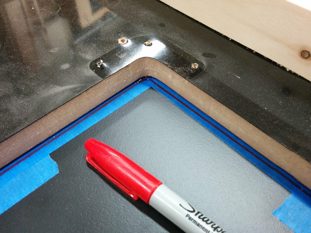
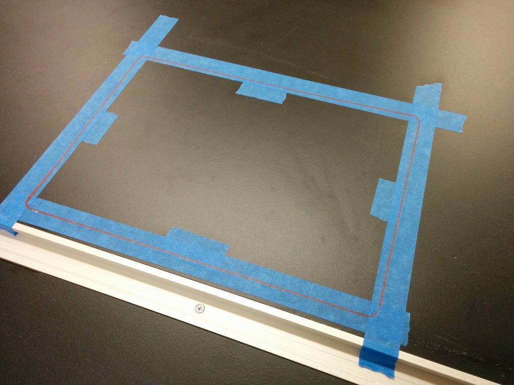
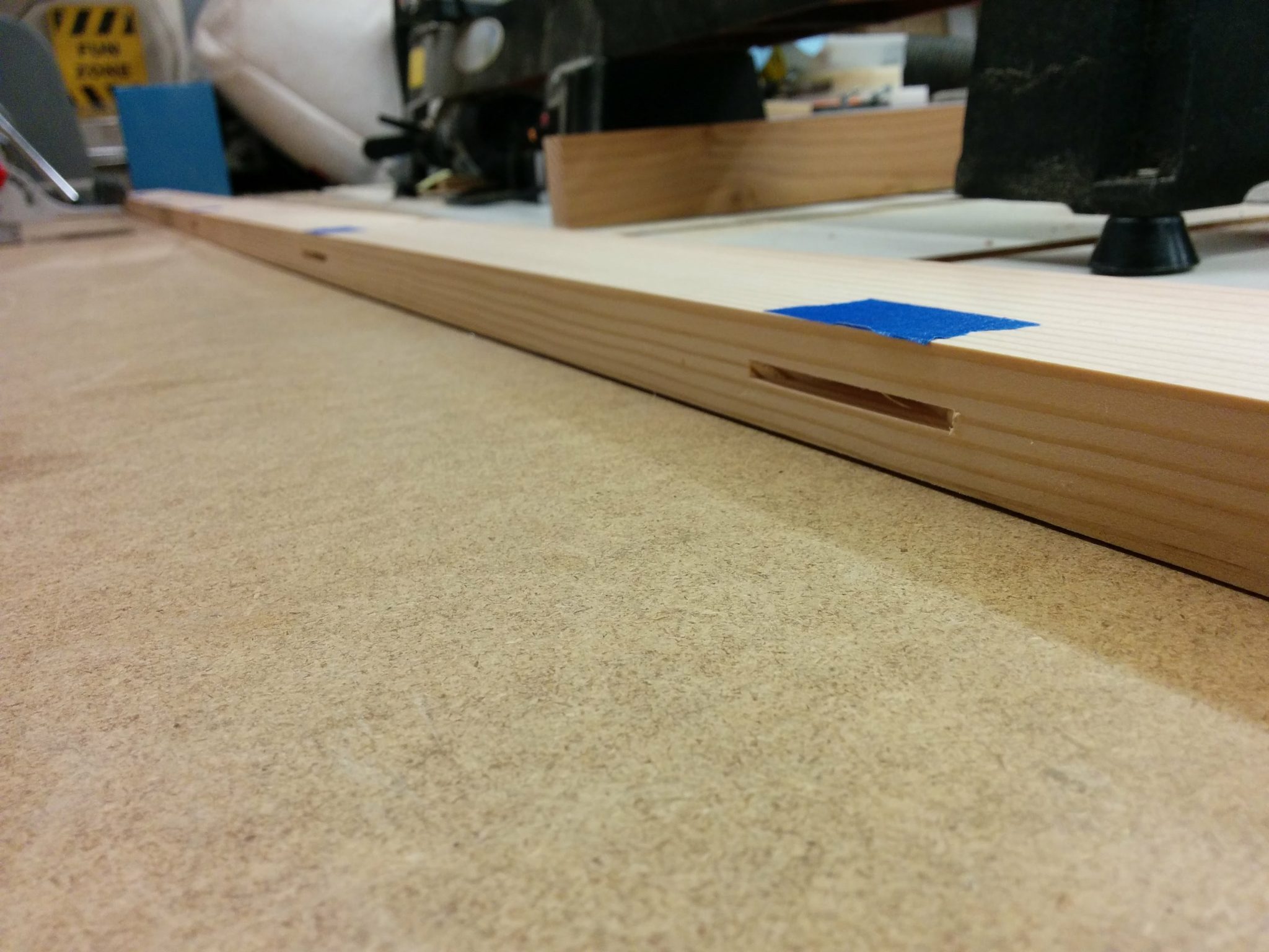
When it was time to drill the holes, I clamped the angle iron to the ends of the bench-top pieces so I could ensure their placement was correct and that it wouldn’t slip.

I clamped the metal to the wood so I can drill accurately.


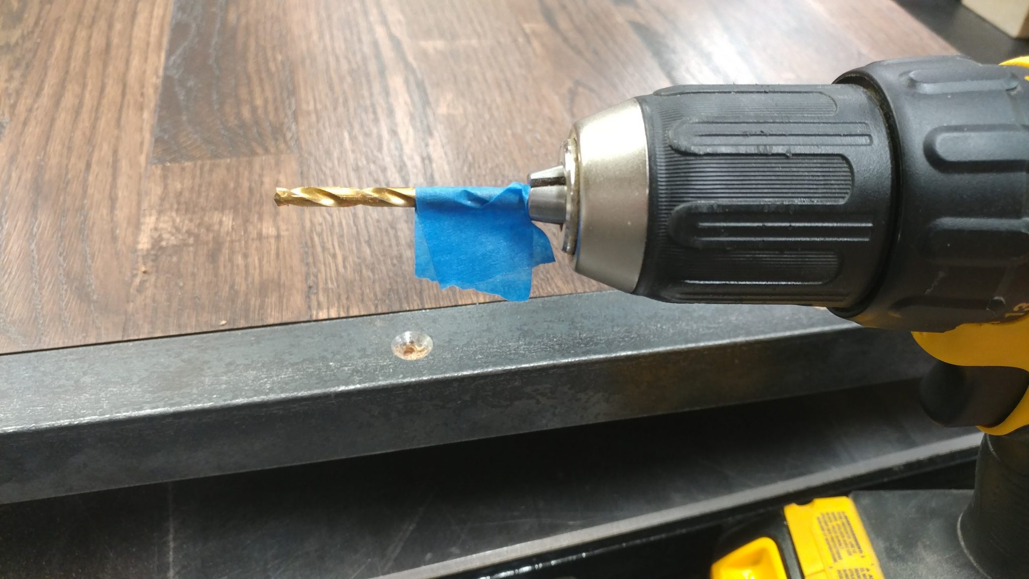
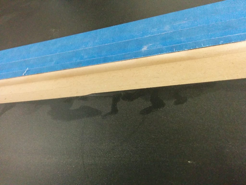
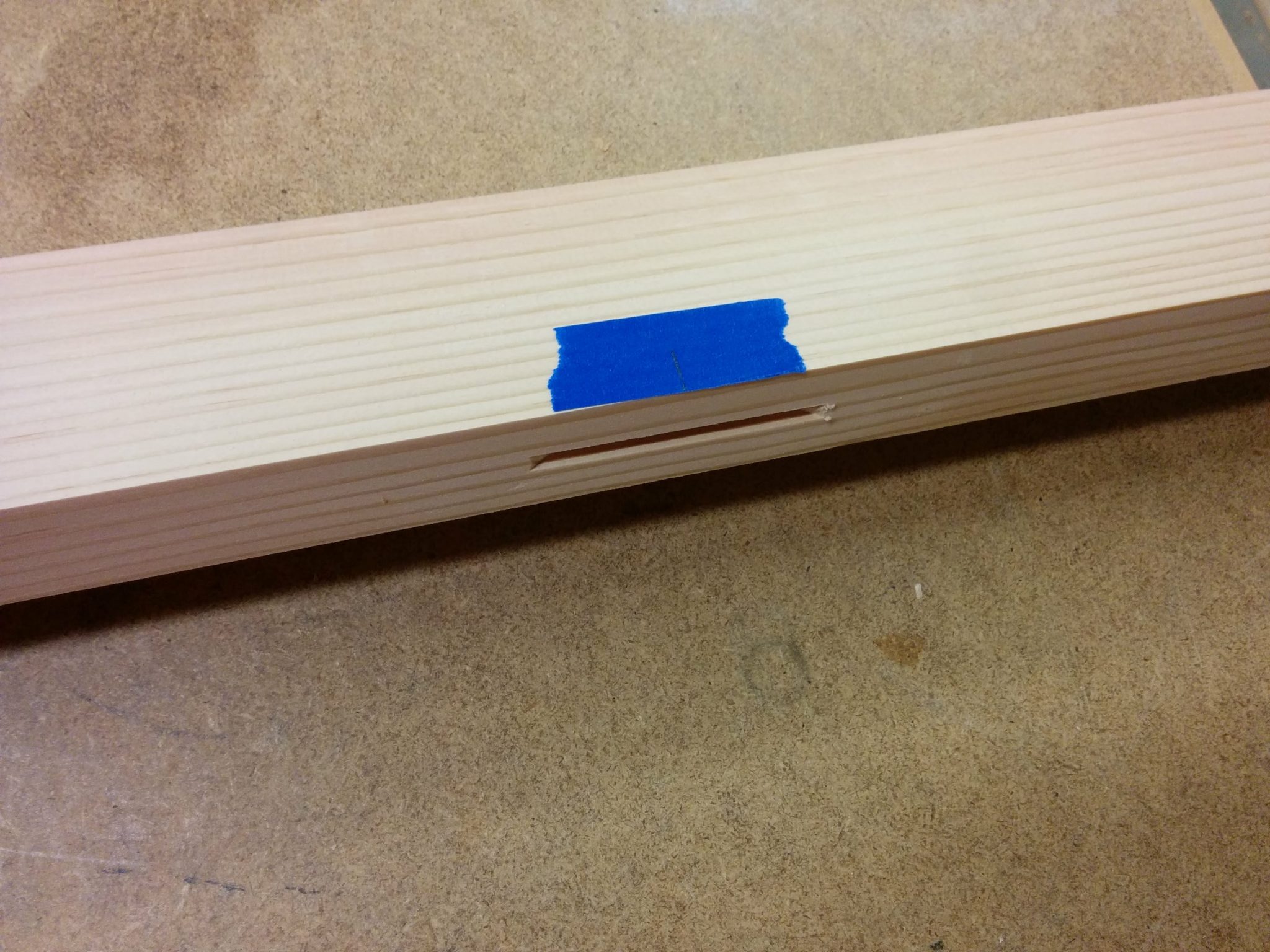
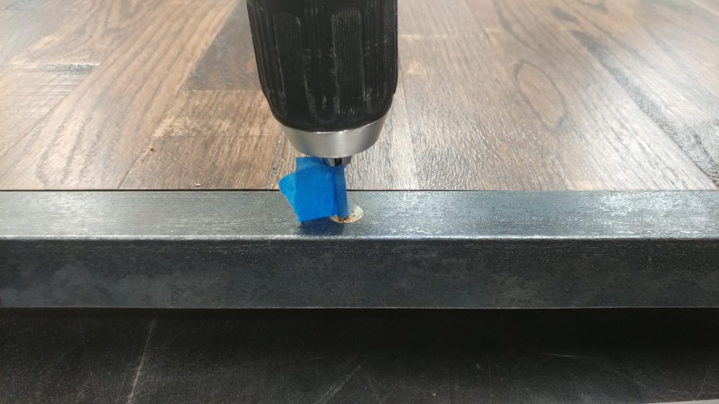
I used some blue painters tape on my drill bit to mark the depth of the hole that I needed for the screws.

I marked the desired hole-depth with some painter's tape.


I drilled just to the point that the painters tape touched the metal.  This is easy to do if you watch the shavings that gather around the hole you are drilling.  When the tape starts to brush them aside, stop drilling.

I drilled down till the tape was flush with the top of the metal.


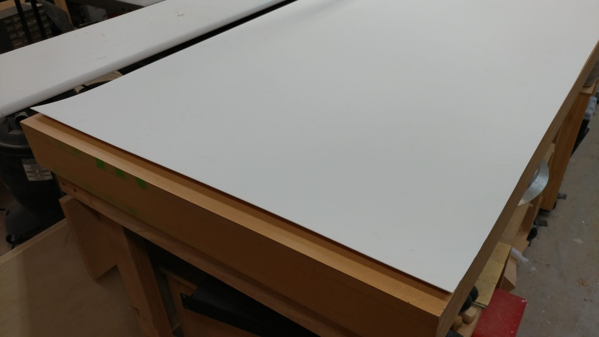
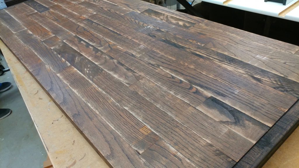
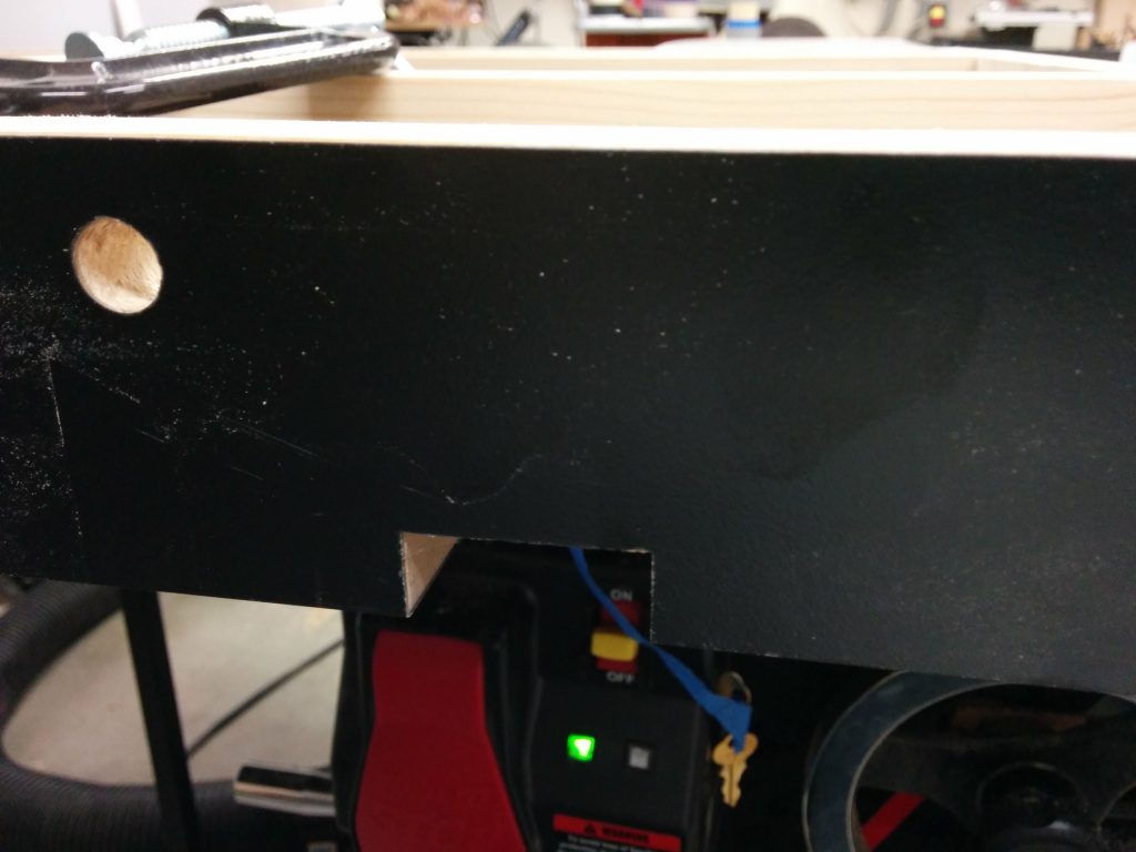
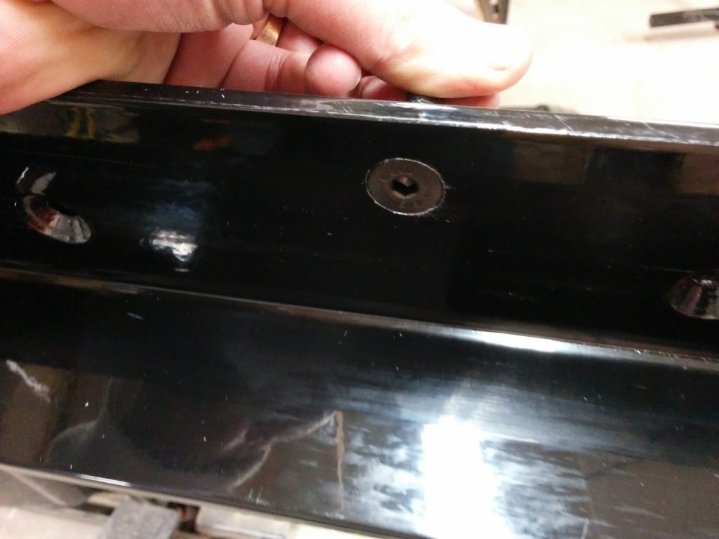
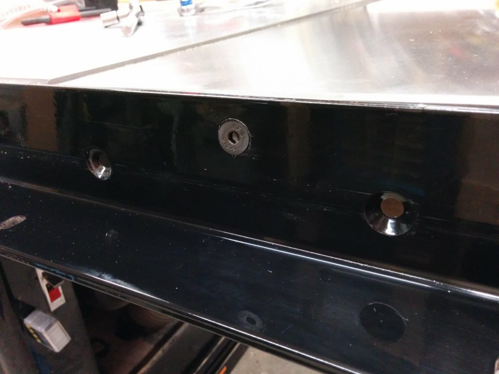
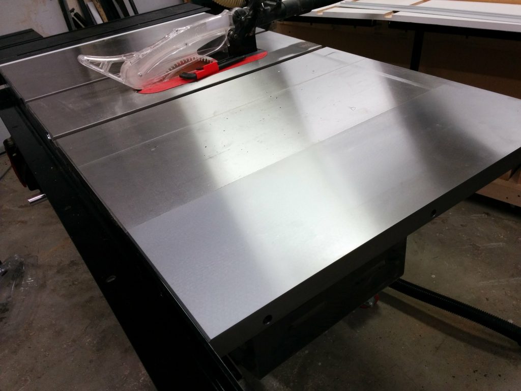
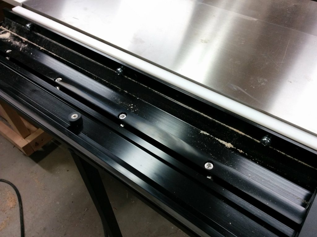
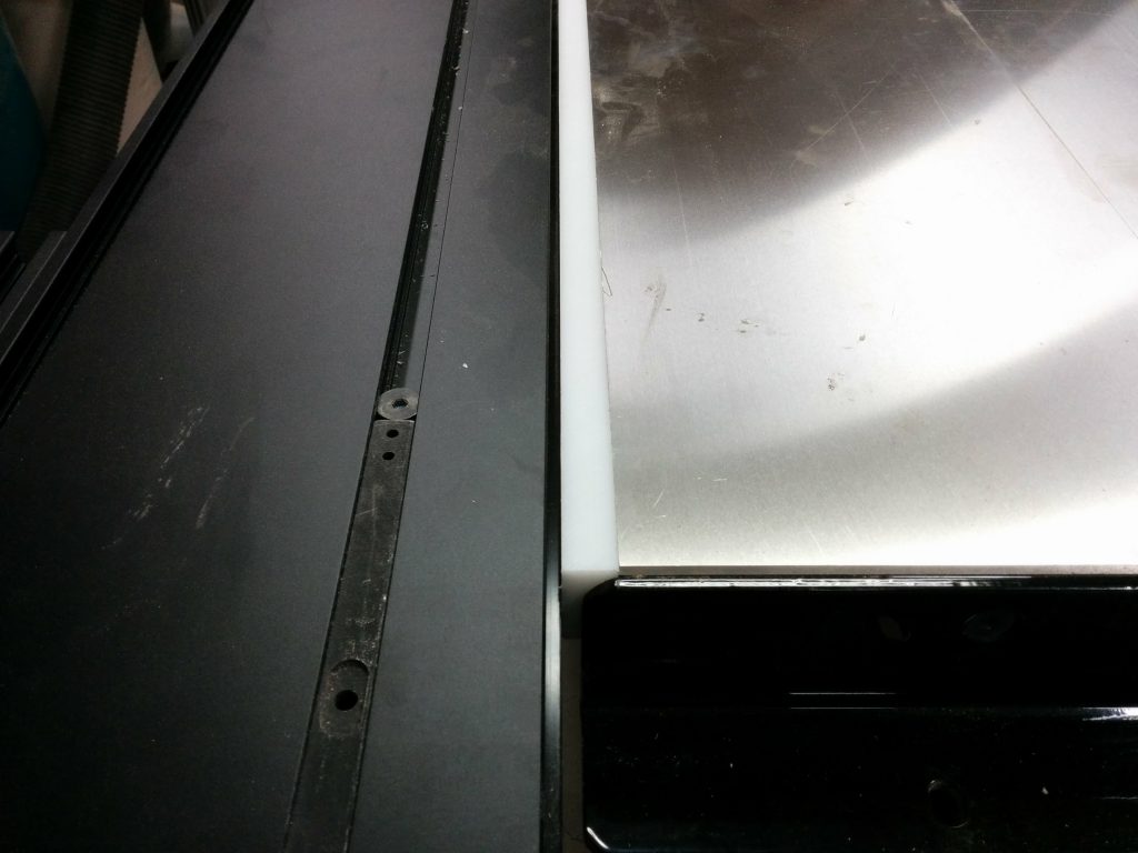
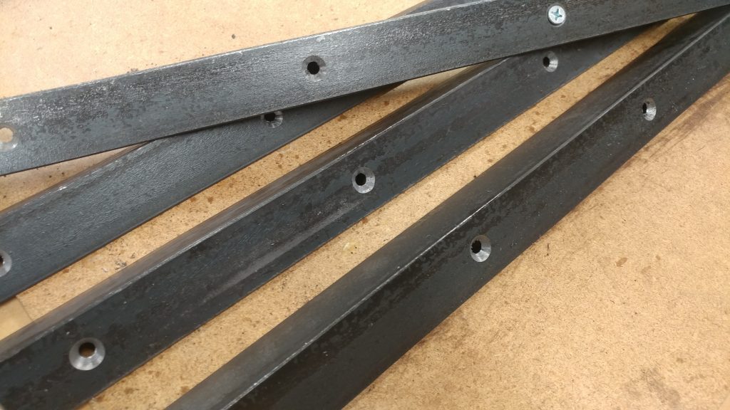
The pieces were then attached with screws. Now the bench-tops are officially done.
Twenty screws total are used to attach the angle iron.


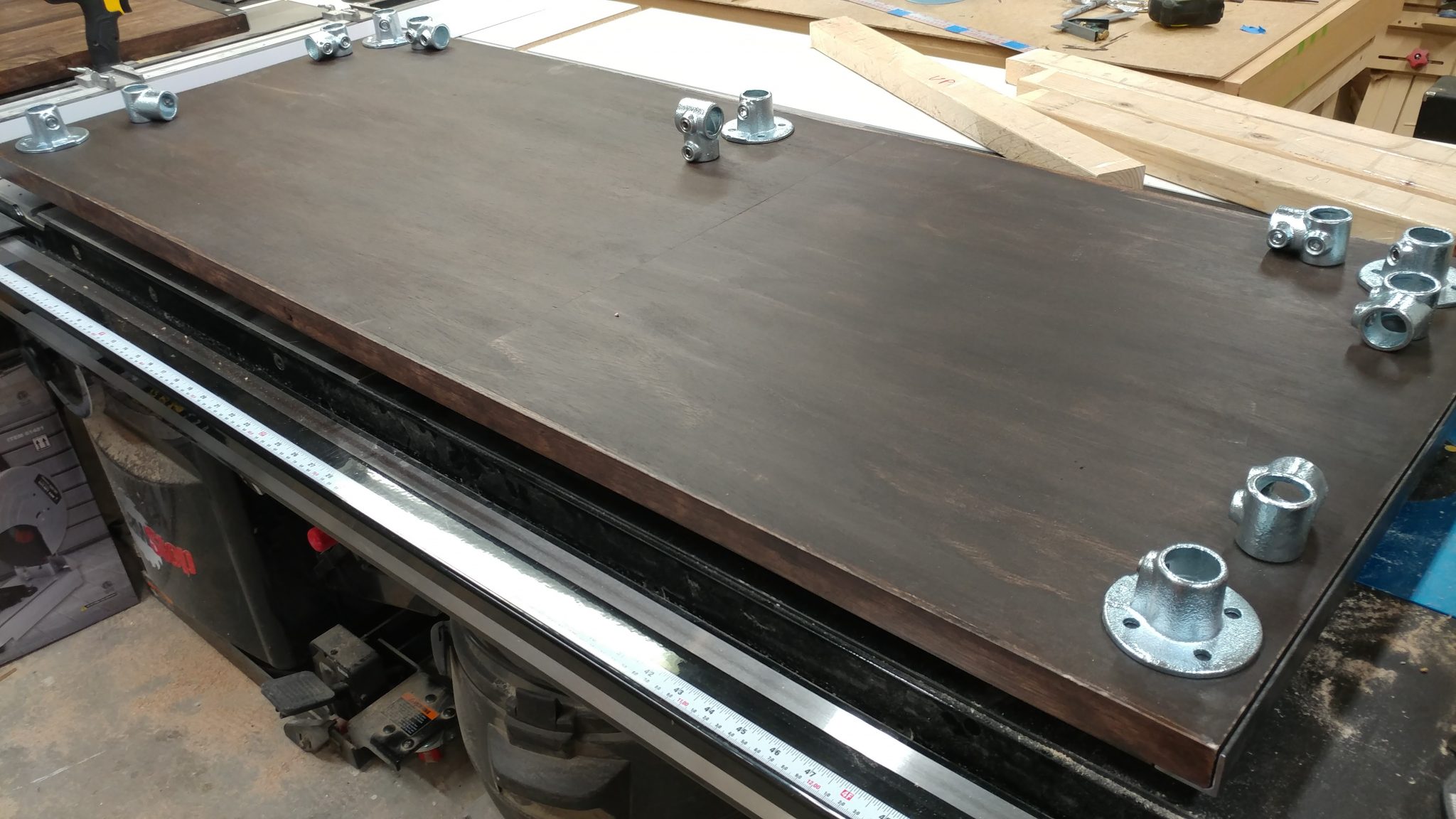
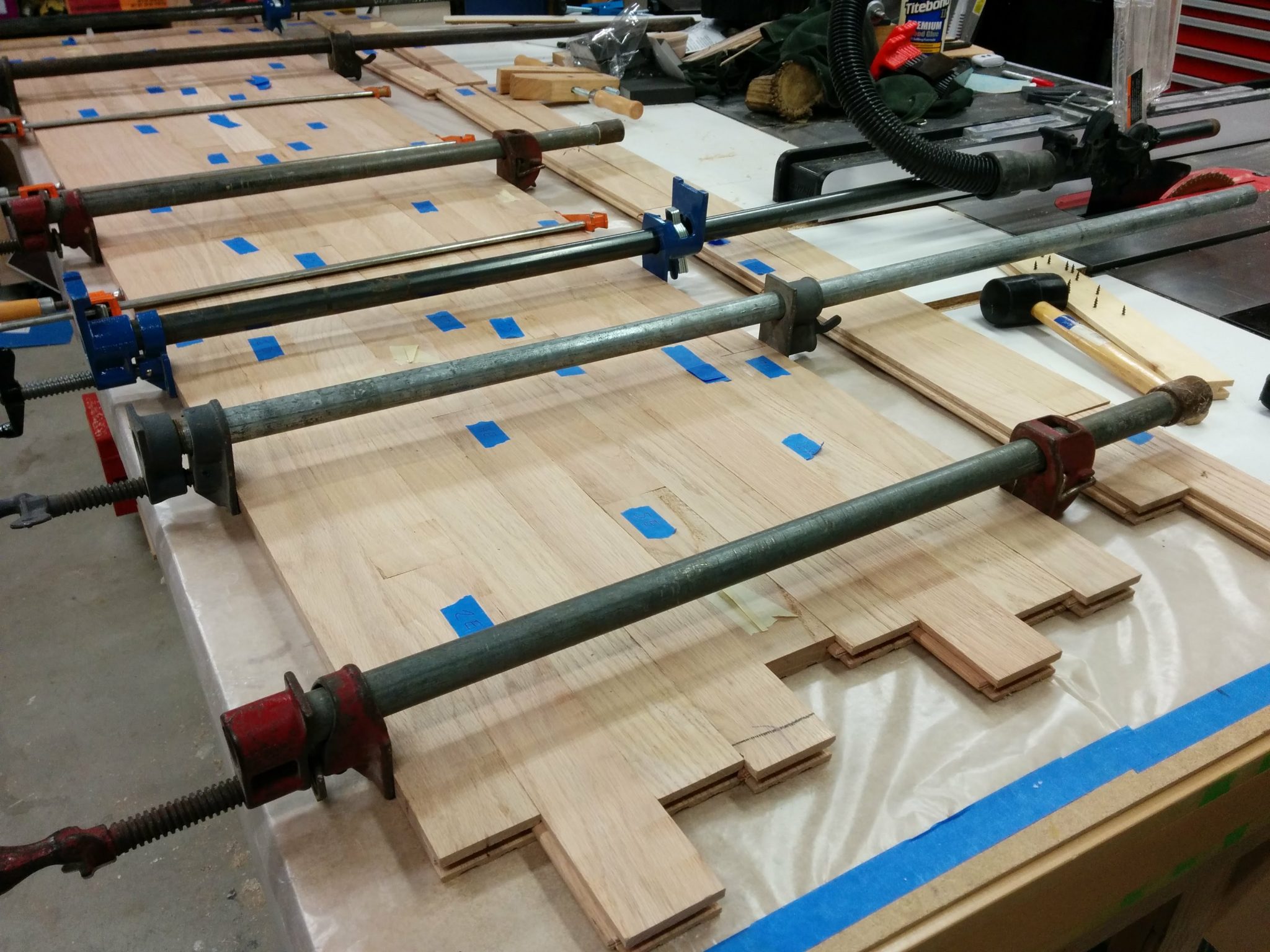
Attaching the legs to the bench-top.


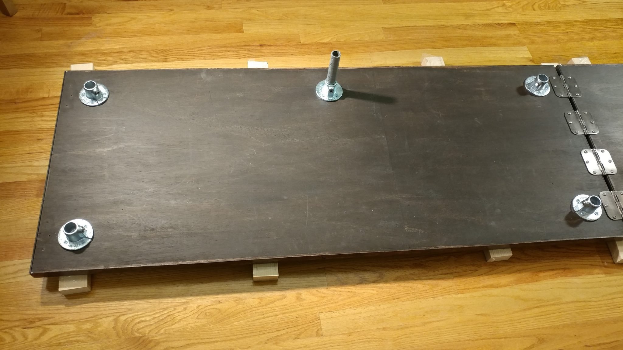
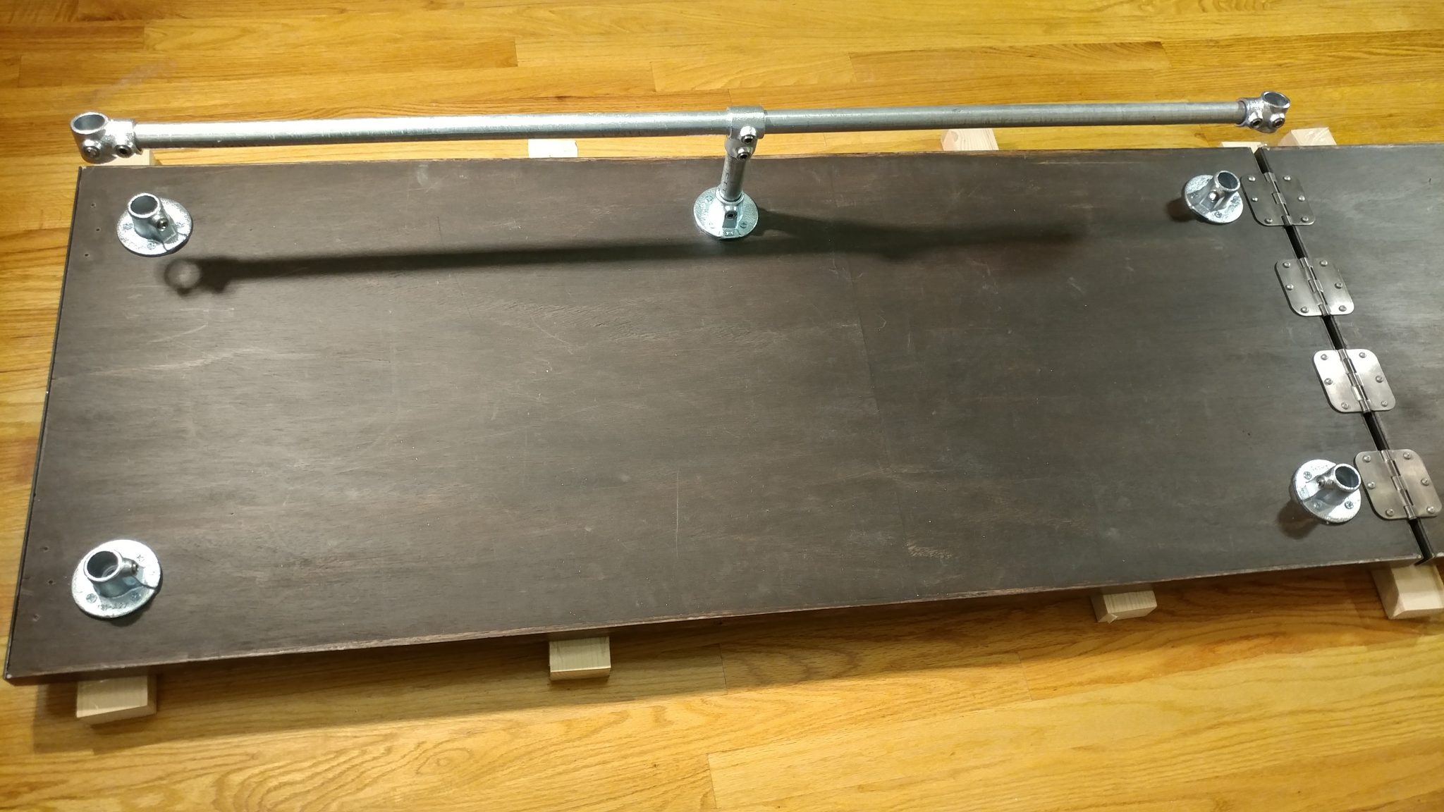
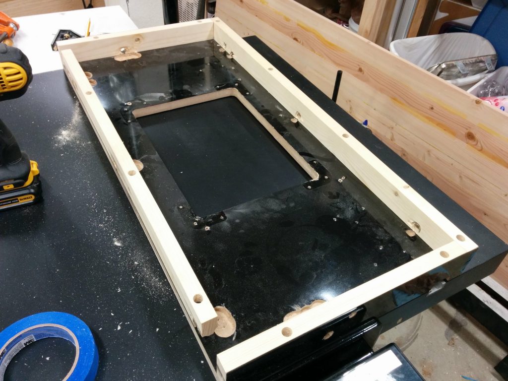
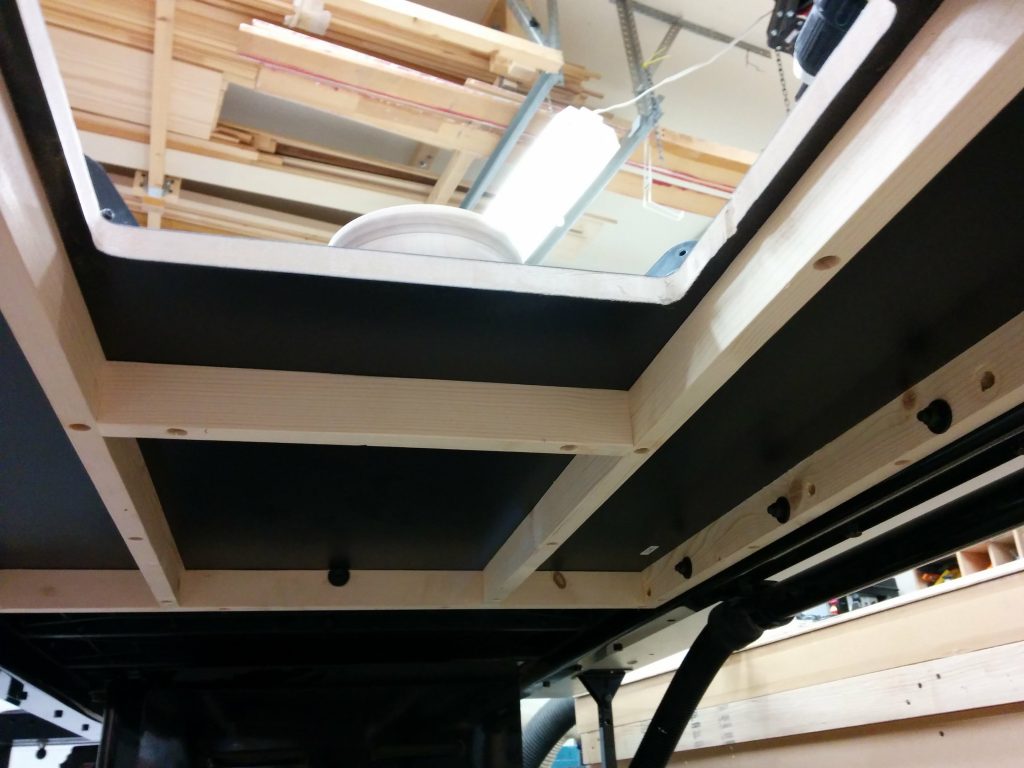
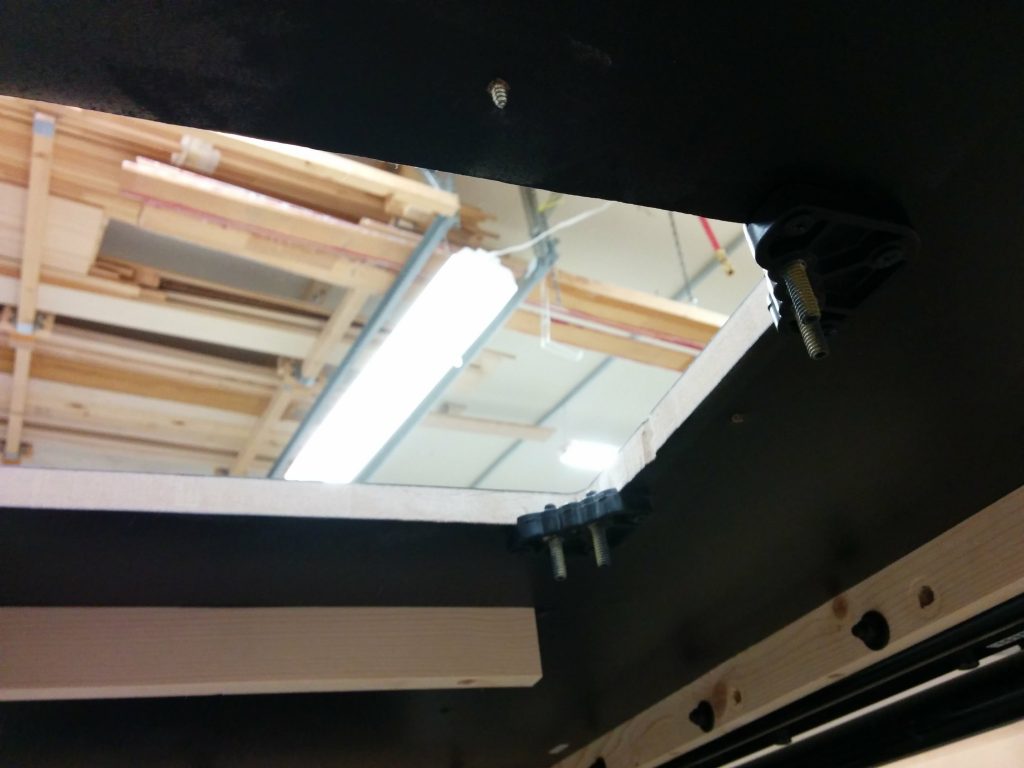
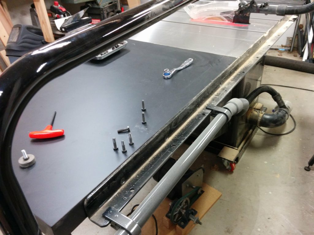
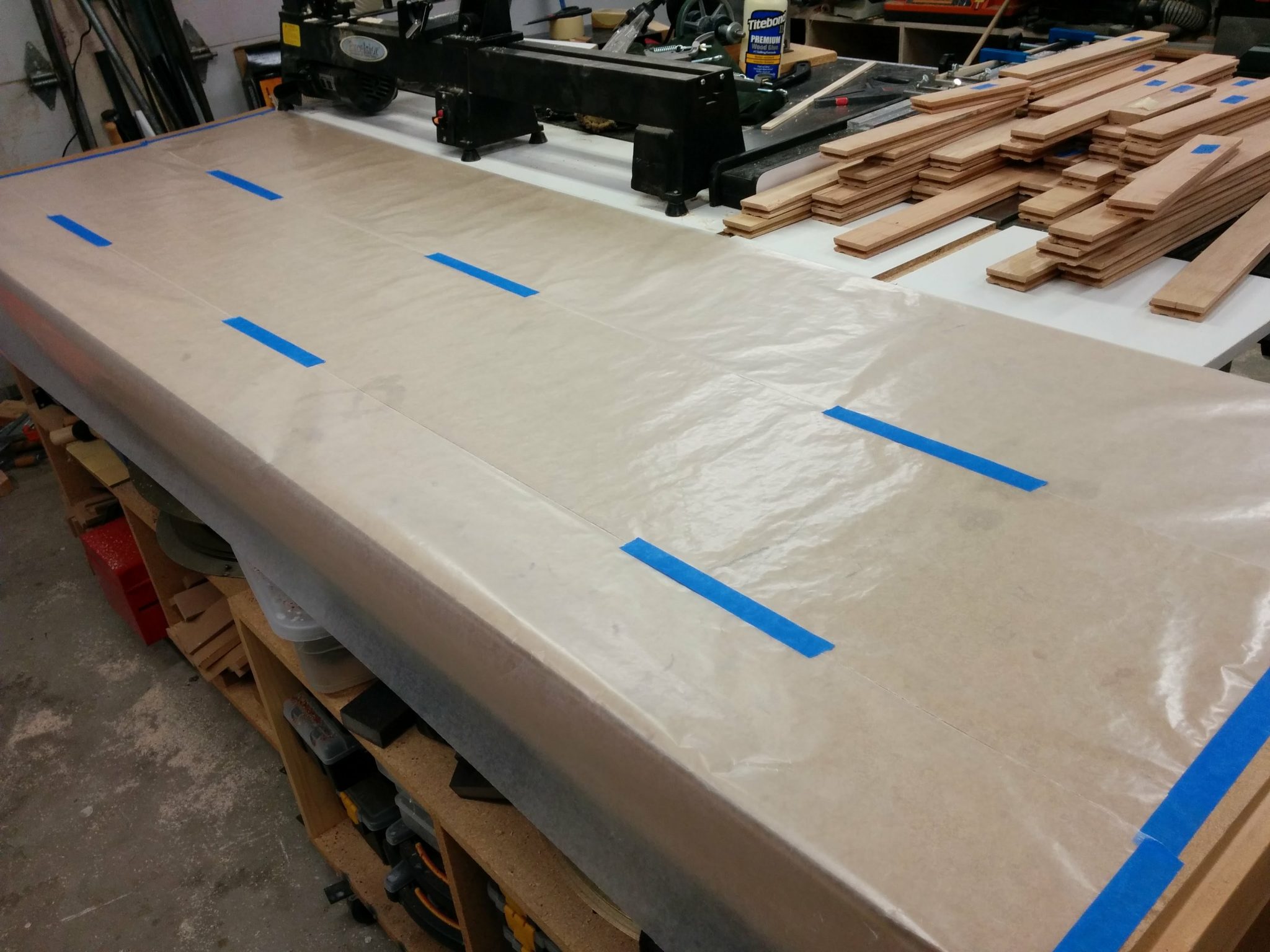
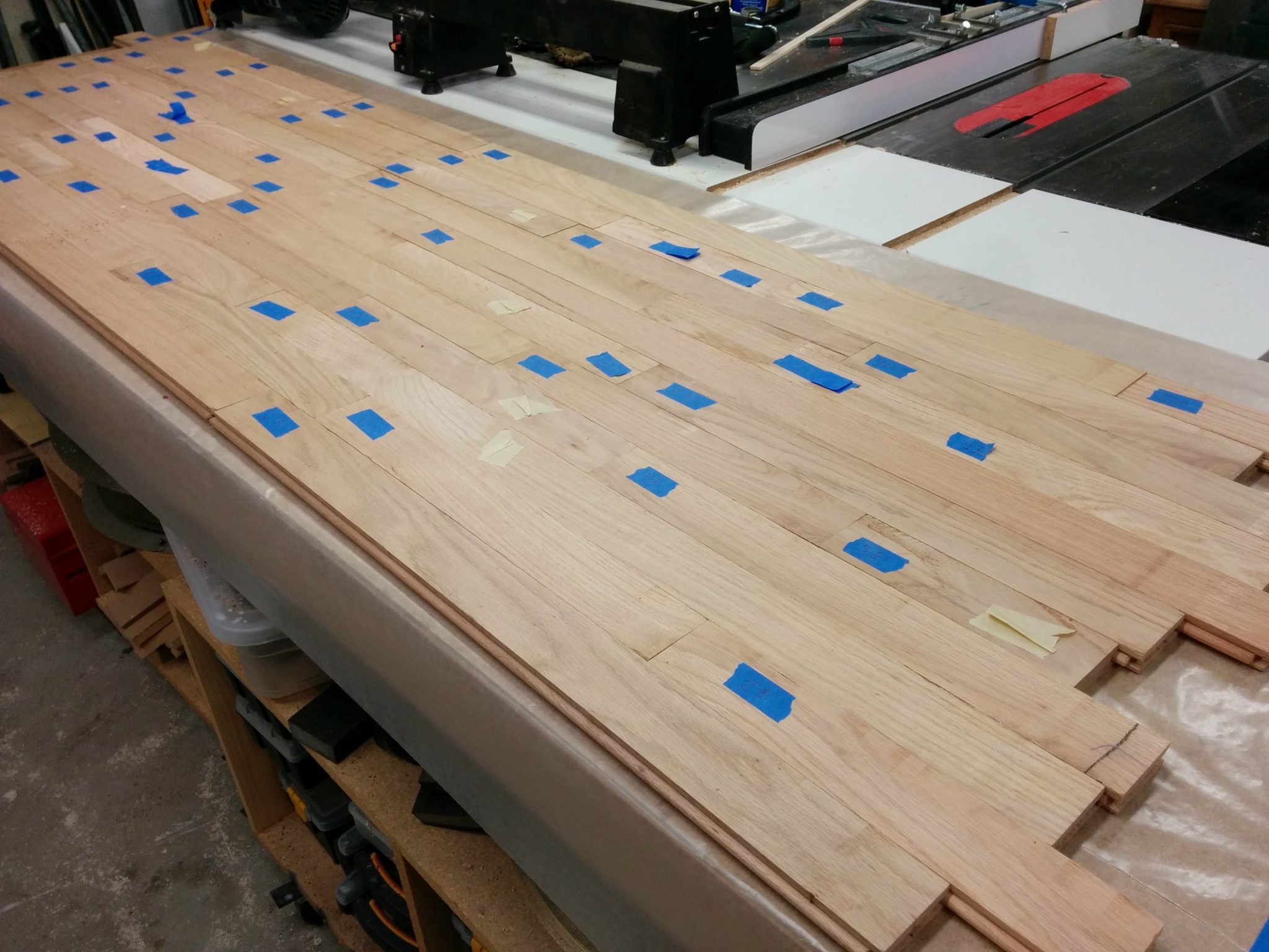
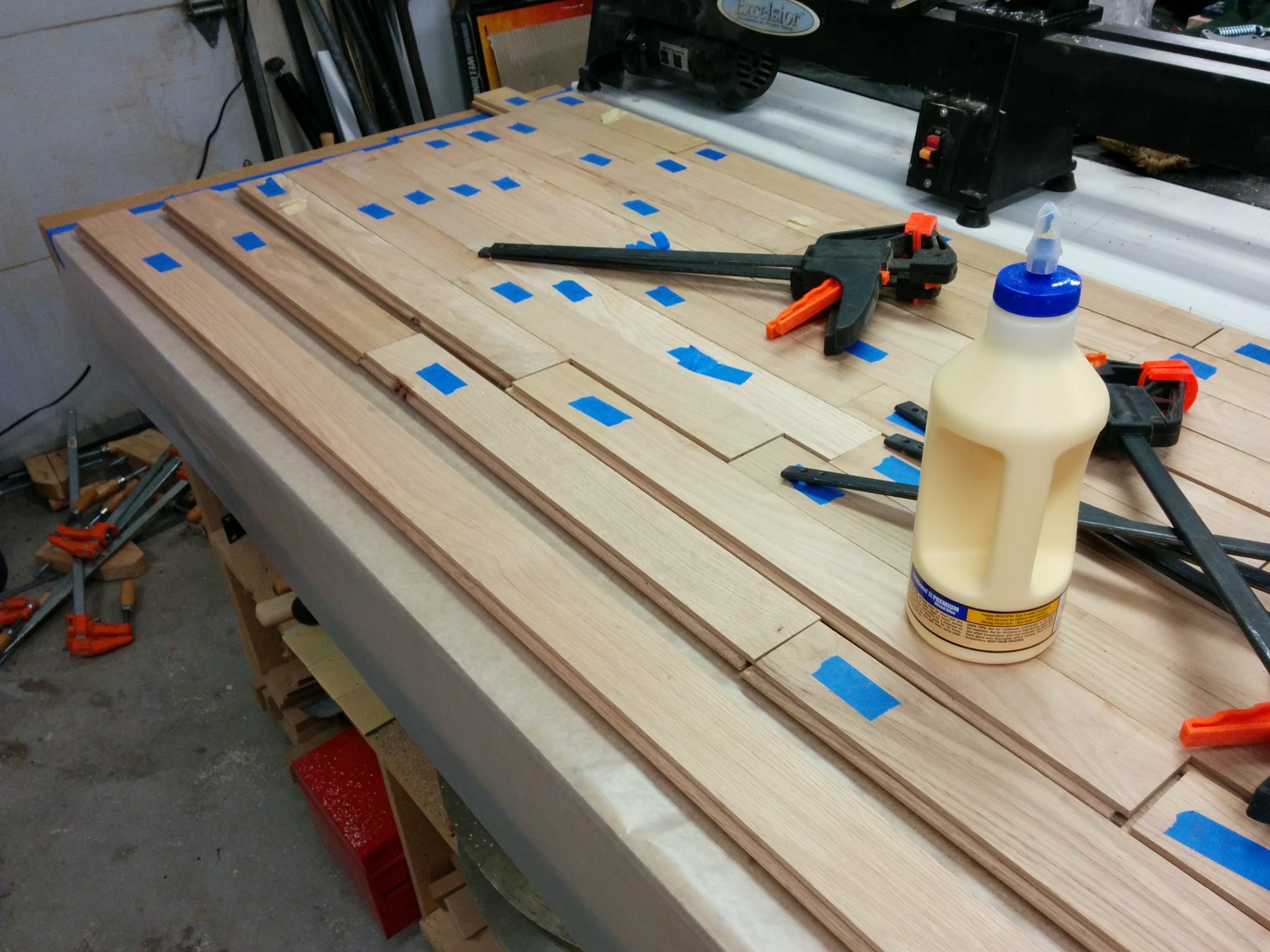
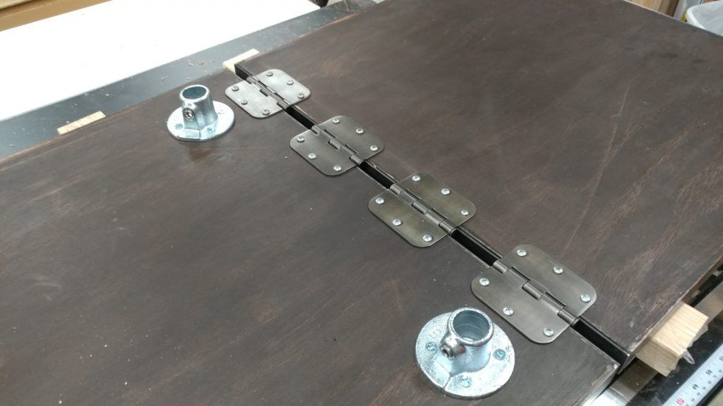
I am using hardware by Steel-Tek to create the legs for this desk. To get a visual on what pieces are needed where, I laid them out on the underside of the bench-top in the approximate area where they will be attached.

I gathered up the hardware and set them up where they were going to be installed.


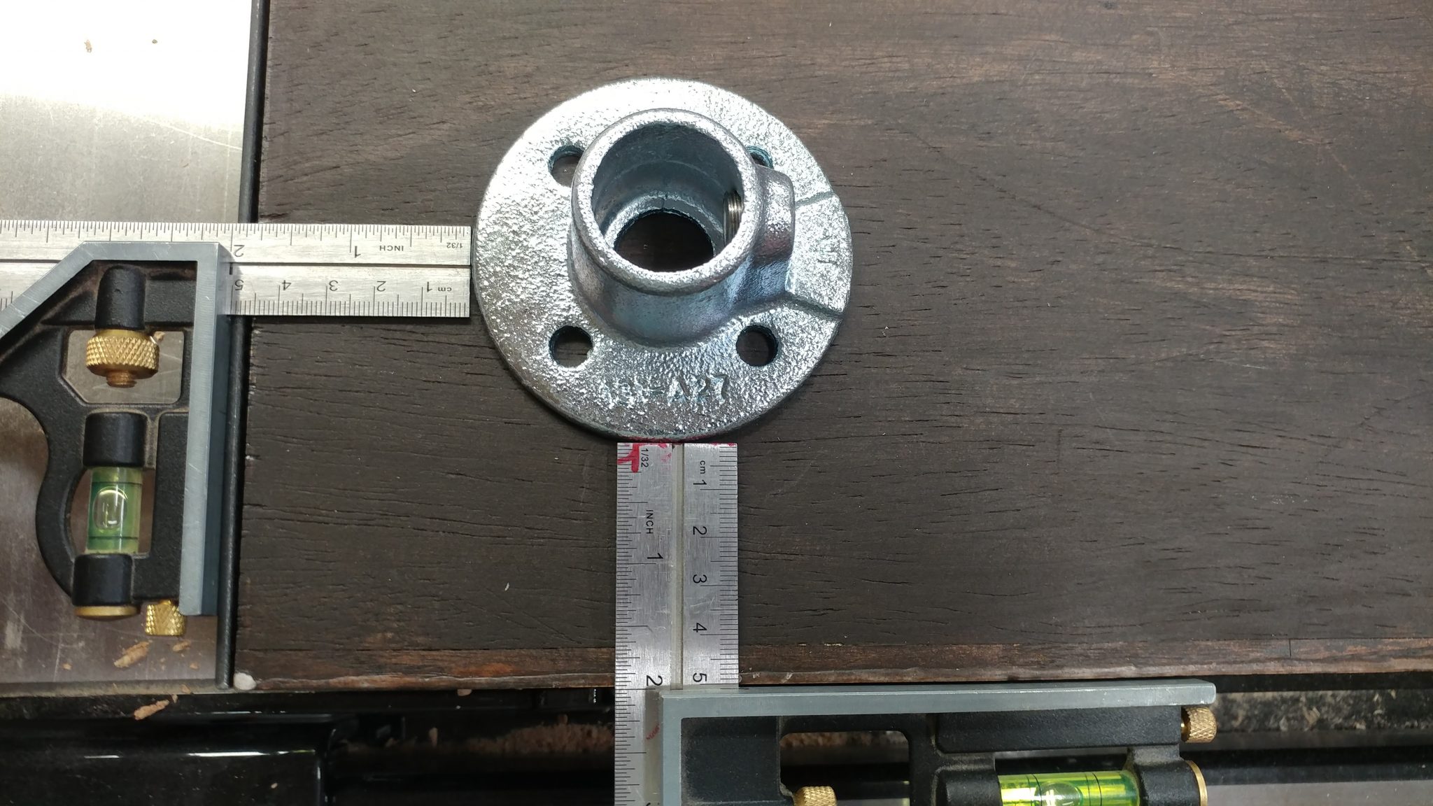
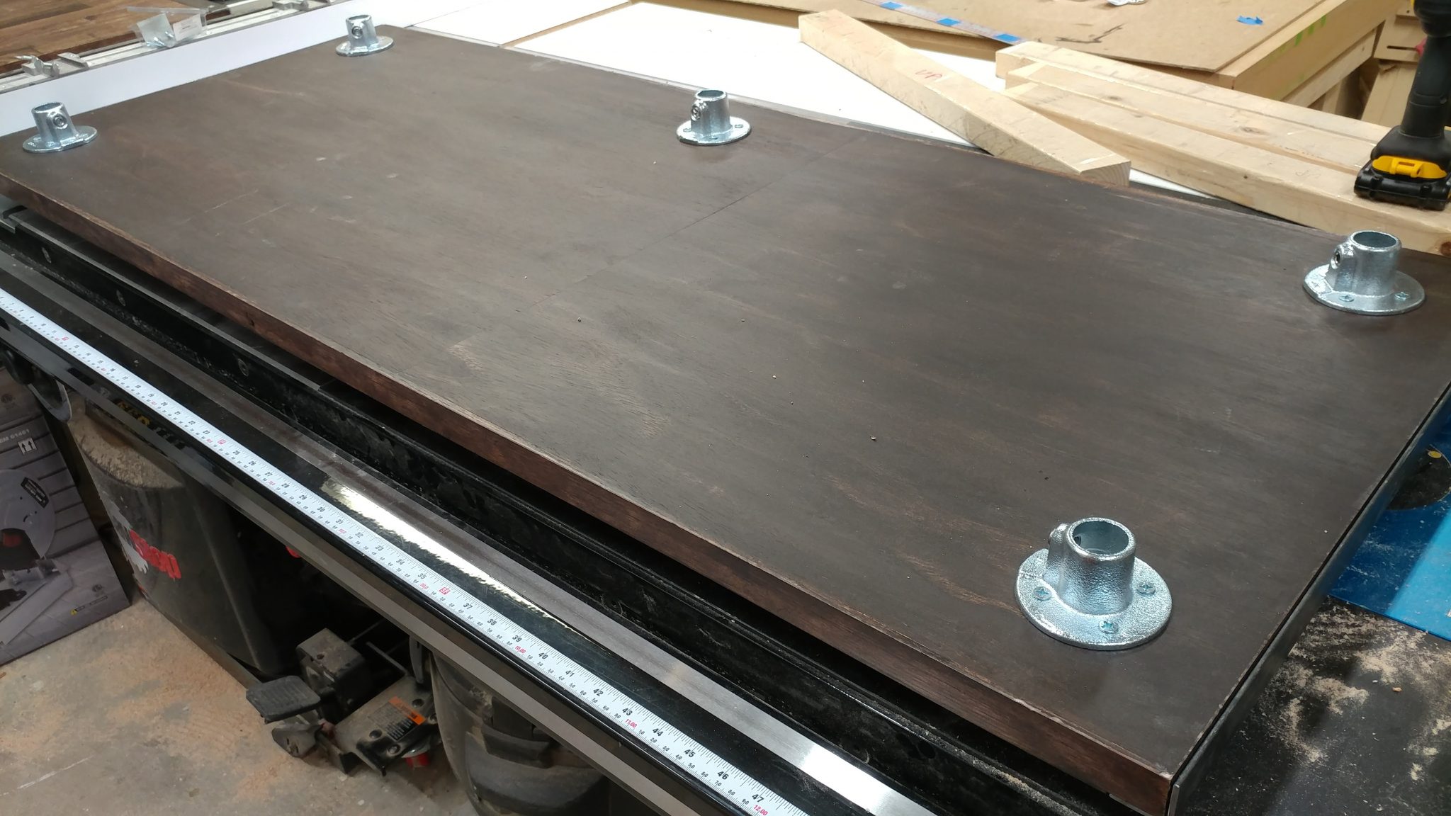
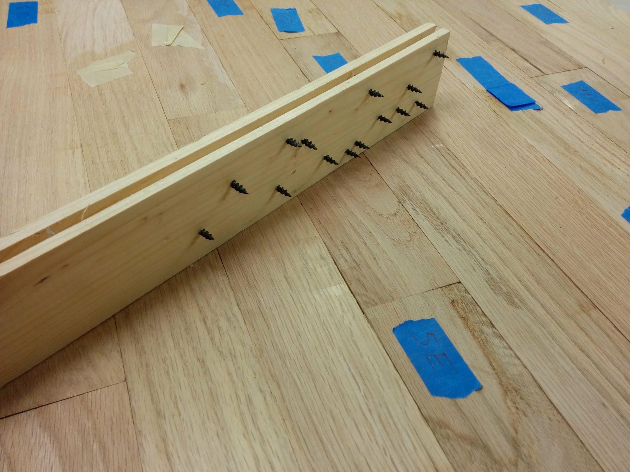
I attached a 3/4″ flange (part no. 673-104HC) in each of the four corners of the main bench-top piece. I set them 2″ in from each edge.

I arbitrarily decided to position the legs 2" in from each edge.


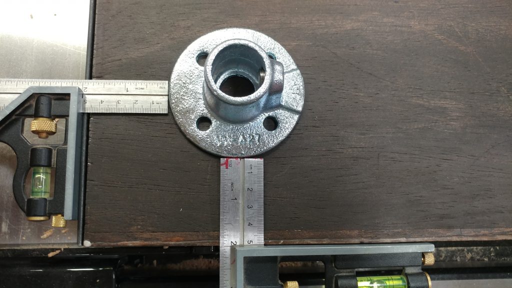
Four screws were used to attach each flange. I also added a fifth flange along the back edge which will help support the bench-top along the length.

All of the flanges have been attached to the underside of the benchtop.


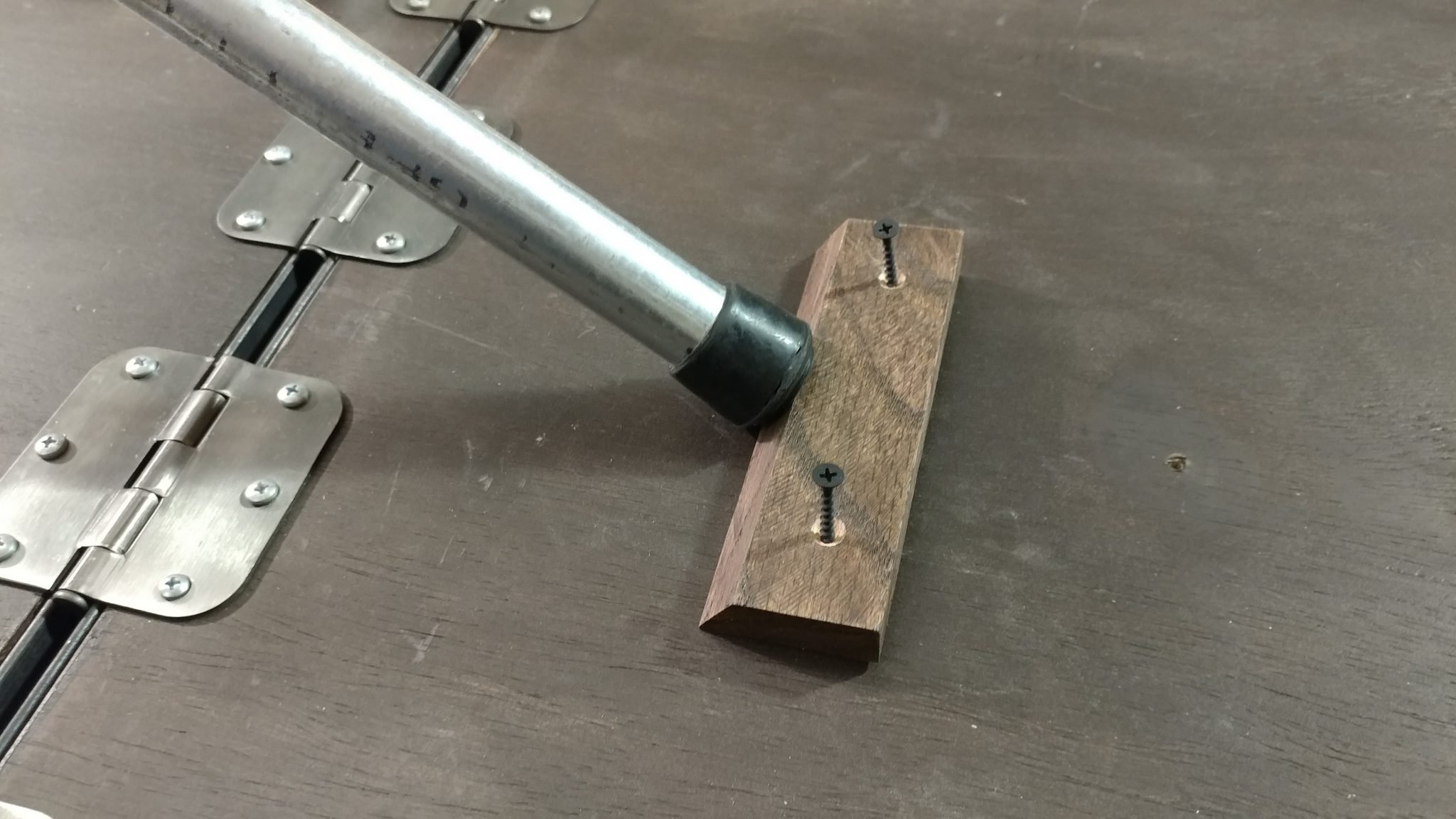
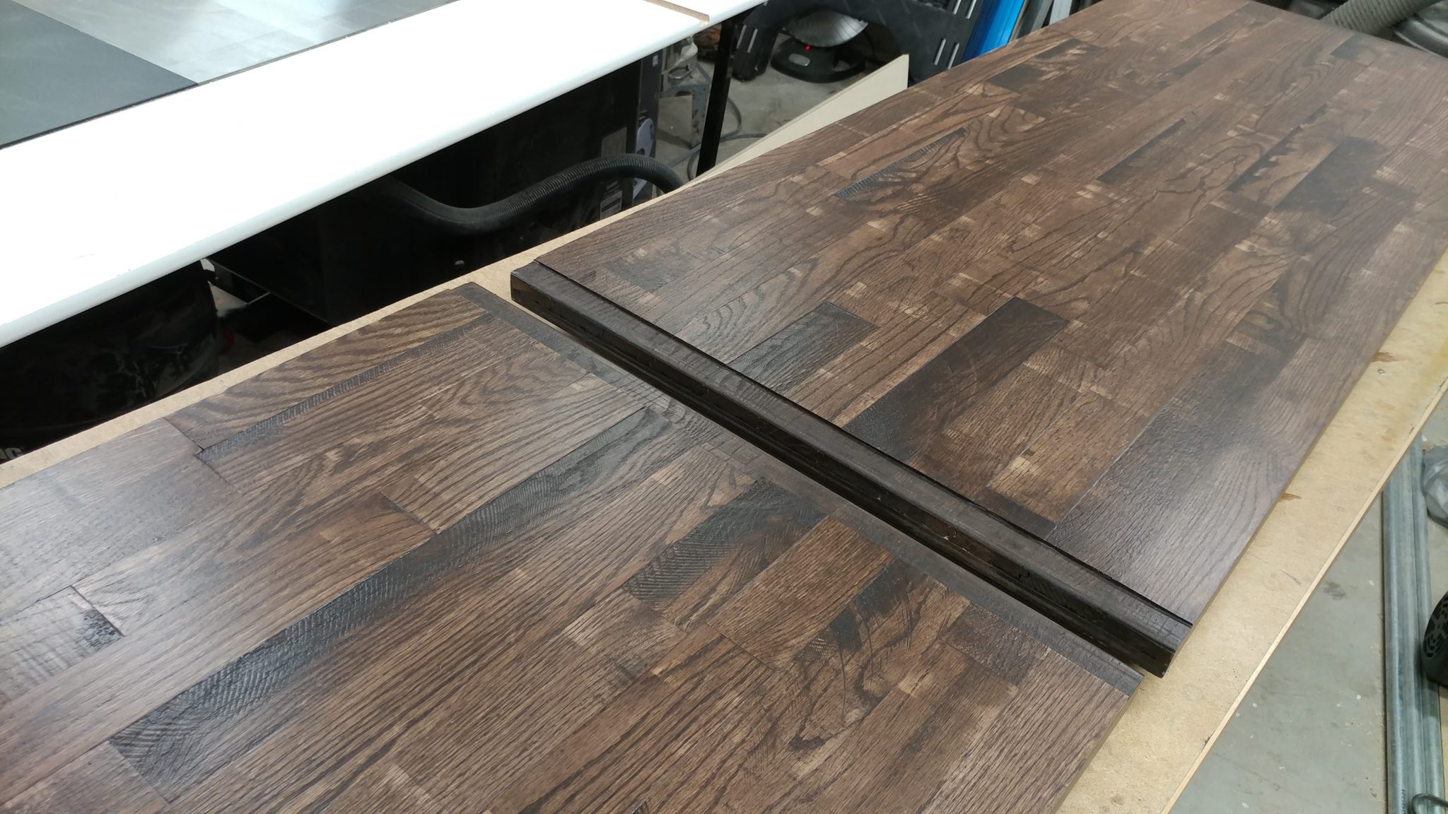
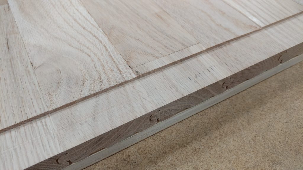
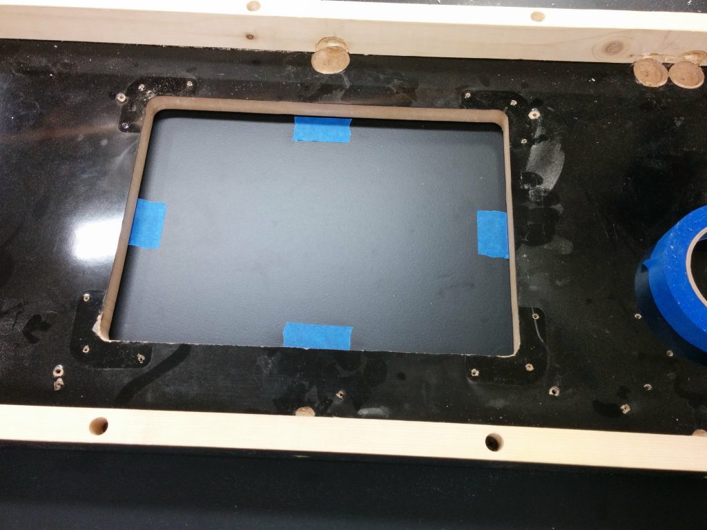
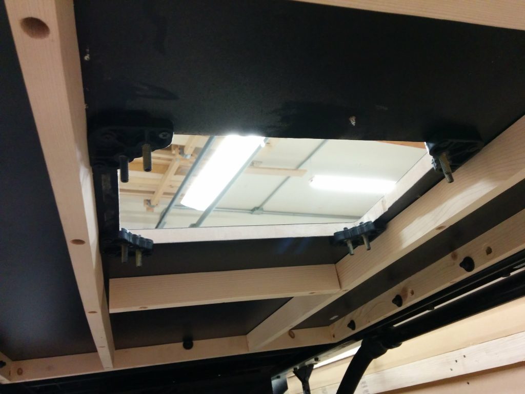
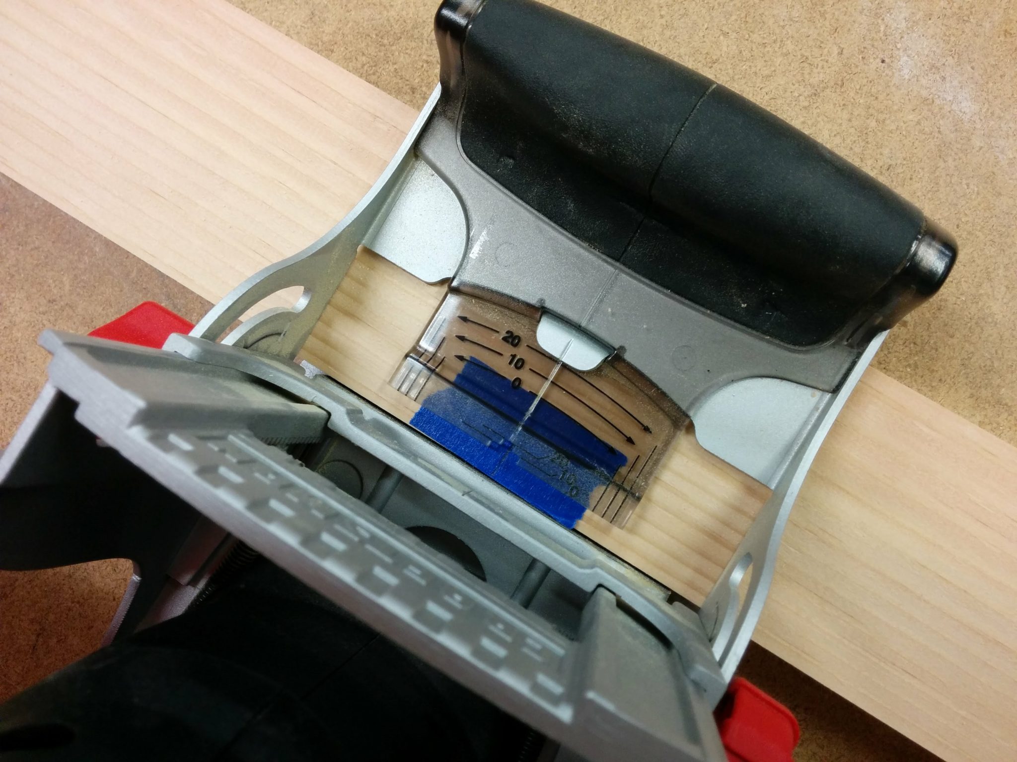
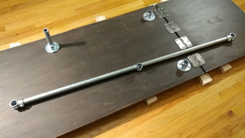
Since I still had the hash marks on my shop rule from when I drilled the holes in the angle iron, I laid that out and used it to arrange the hinges for attaching the extension wing. I debated about using a piano hinge for this as it would provide better support since it would be screwed into the side rather than from underneath. In the end, I decided to attach four hinges along the underside and I’ll just keep an eye on it. I can always come back and change it later if it starts to weaken.

Laying out the hinges in their approximate location.


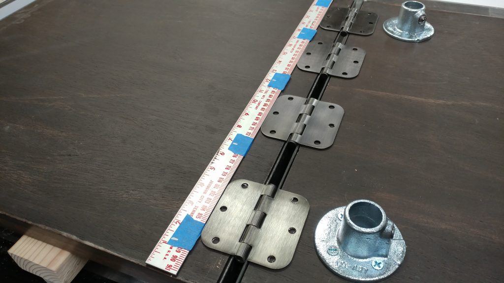
I ended up spacing the hinges a little over 2″ apart.  This measurement will vary depending on the hinge that is used.

I decided on a 2-3/16" gap between the outer hings and the inner ones.


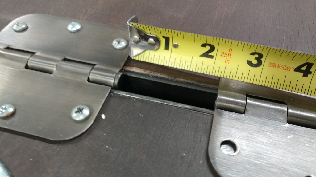
Each hinge was attached and they seem really solid so I’m not too worried. I needed a slight gap between the main table and the wing because of how the wing is going to be held upright. This will be explained later.

All of the hinges have been attached.


Back to my chop saw to cut down the 3/4″ tubing to the various lengths that I needed.

Cutting the steel tubing to size with a metal chop saw.


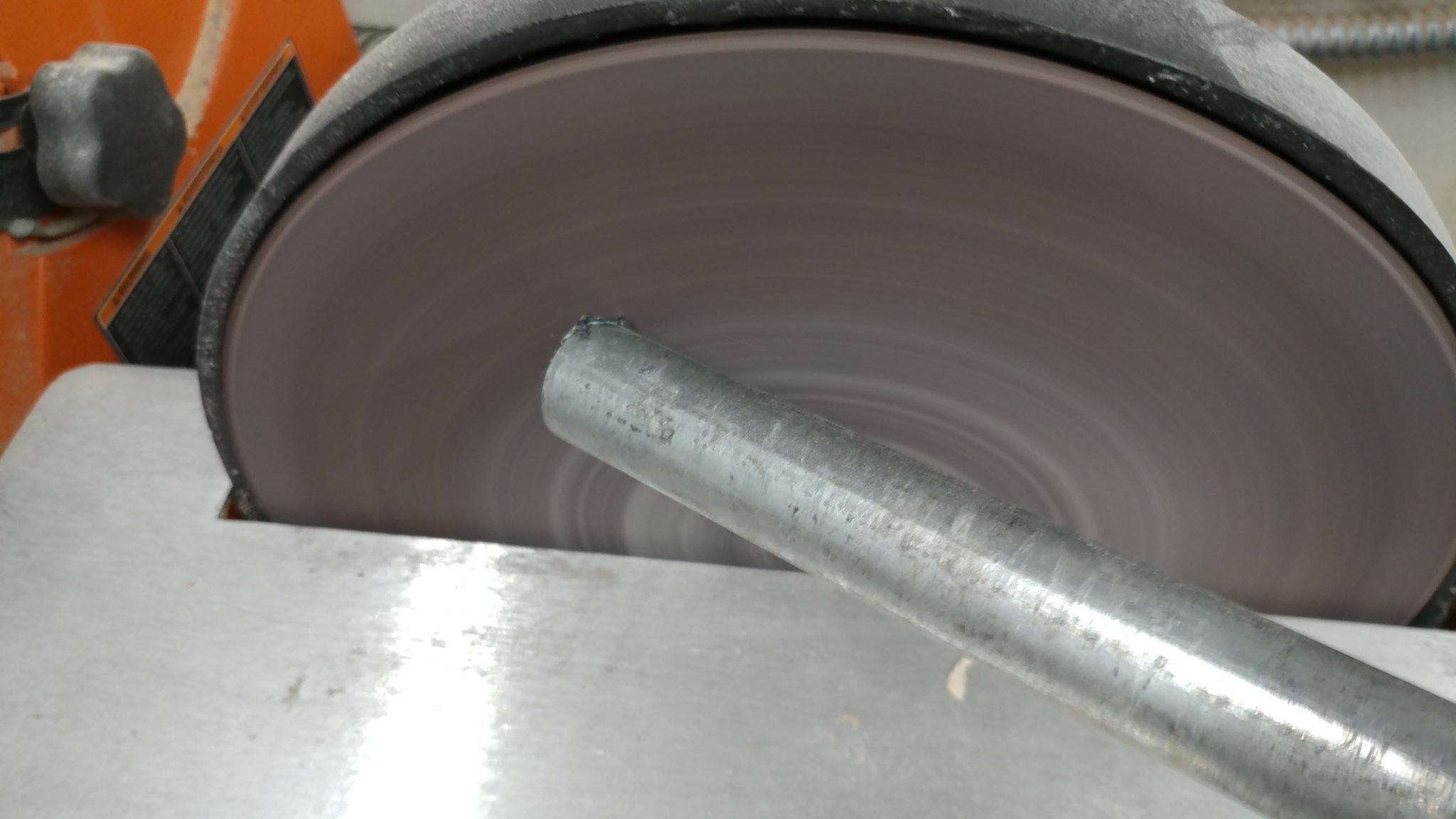
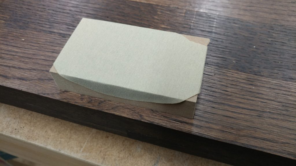
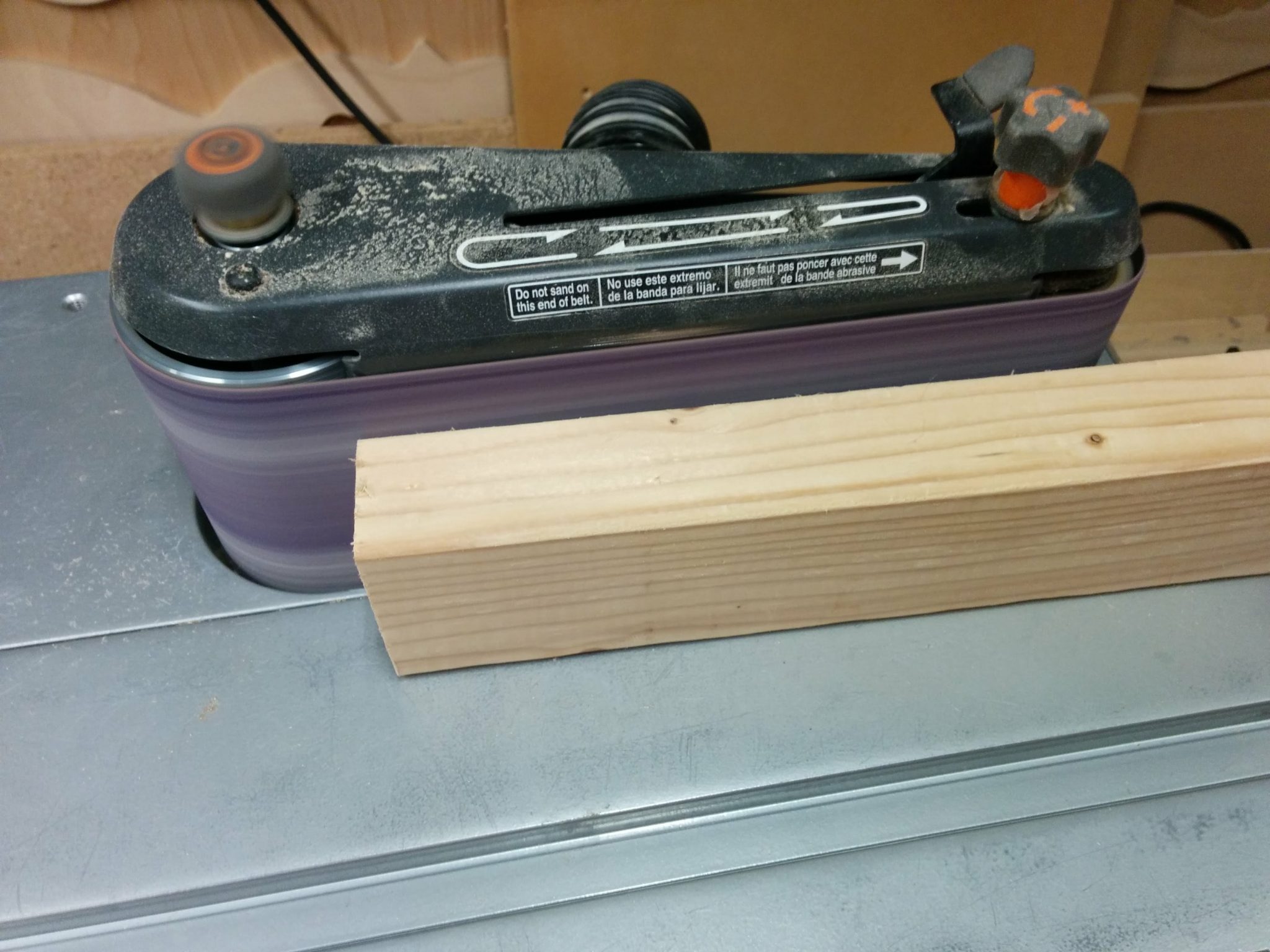
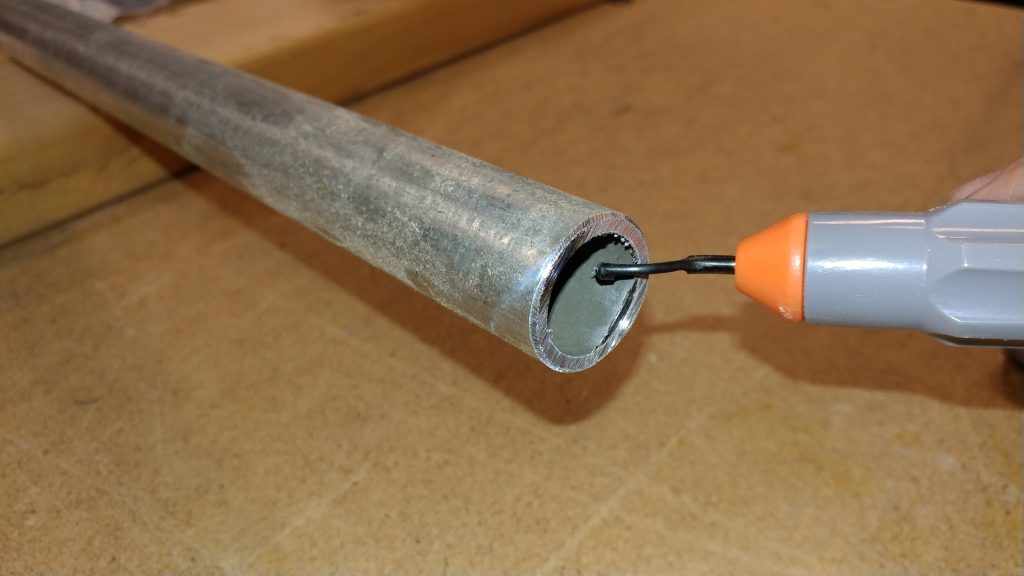
Using a disc sander, I added a slight chamfer around the edge of each piece of pipe in case anyone wants to take this bench apart in the future. I wouldn’t want anyone getting cut on the sharp edges.

Adding a slight chamfer around the ends of each piece of pipe.


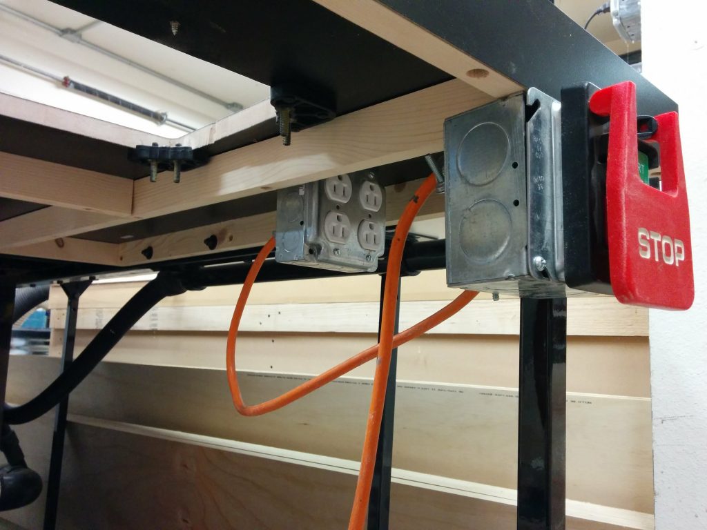
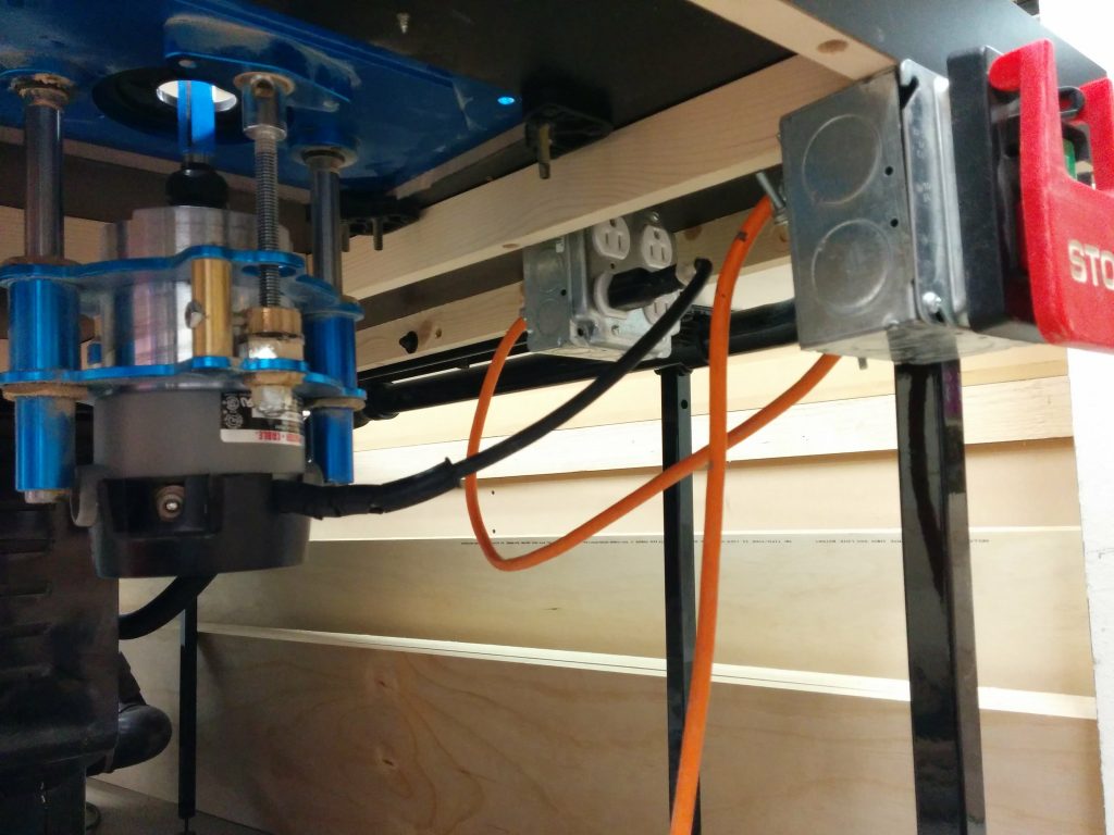
As I was cutting these down, I realized that this piping would allow me to run wires through them in case I wanted to add a few outlets along the top. If you’ve ever run conduit, you probably understand the importance of removing the jagged edge along the inside so it doesn’t damage any wires. I did this with a deburring tool.

I removed the inner jagged edge using a deburring tool.


I got all my hardware gathered up. Along with ten single socket tees (670-104HC) from Steel-Tek, I used the following lengths of pipe.

  • (qty: 1) 52″
  • (qty: 4) 28 ¼”
  • (qty: 3) 16″
  • (qty: 1) 12 ½”
  • (qty: 1) 6″

Here are all the hardware pieces that I will need.


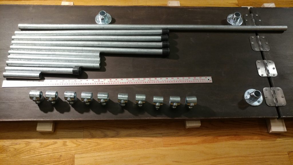
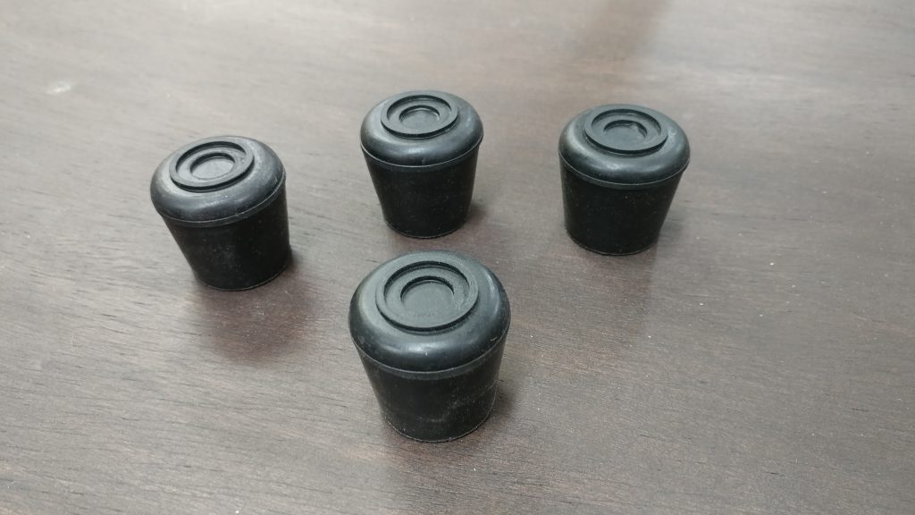
I also used 1″ rubber feet which fit perfectly over the 3/4″ pipe. Four of these were used for the legs and a fifth was used for the extension wing support arm.


I got some 1" rubber feet for the ends of the legs.


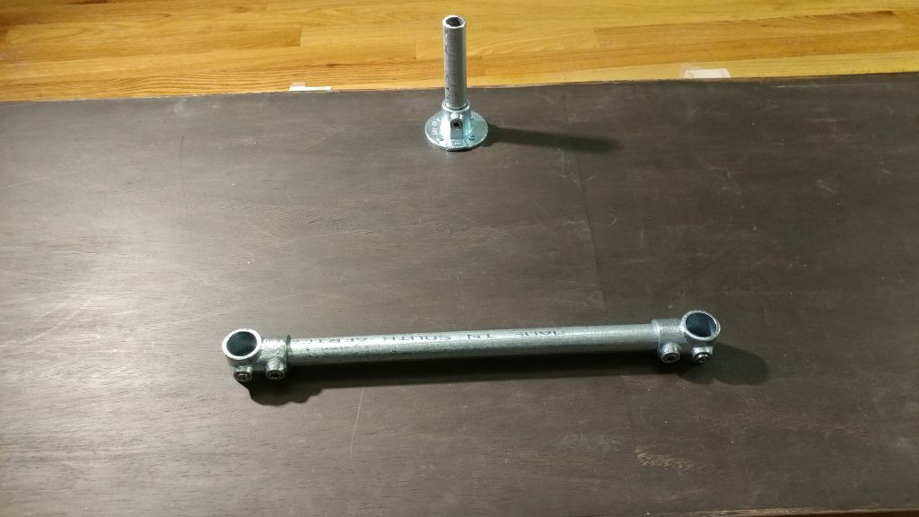
I inserted the 6″ piece of pipe into the center flange and tightened the set screw.

I inserted the shortest piece in the central flange and tightened down the set screw.


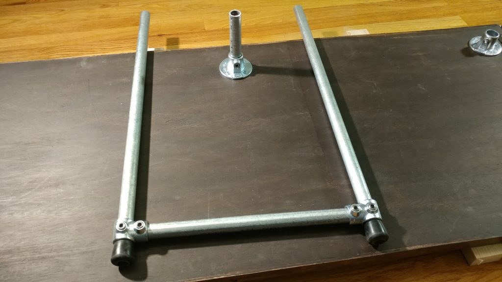
Two single socket tees are then attached to two of the three 16″ lengths of pipe and the set screws are tightened. These will be the horizontal support braces that will go between the front and rear legs.

I made the two horizontal braces using one of the 16" pieces of pipe and two of the single socket tees for each brace.


I slid two legs all the way through the tees on each of the horizontal braces and temporarily tightened the set screws. I set these aside for later.

I slid one of the braces on two of the legs and temporarily slid it to the far end and tightened down the set screws.


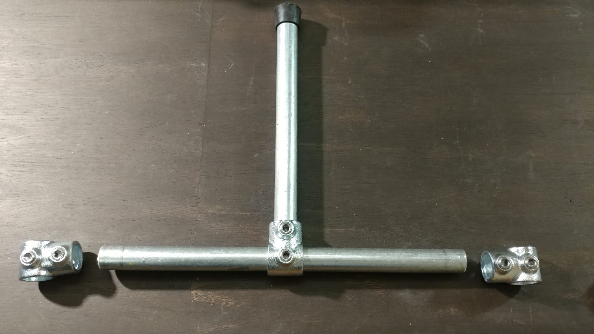
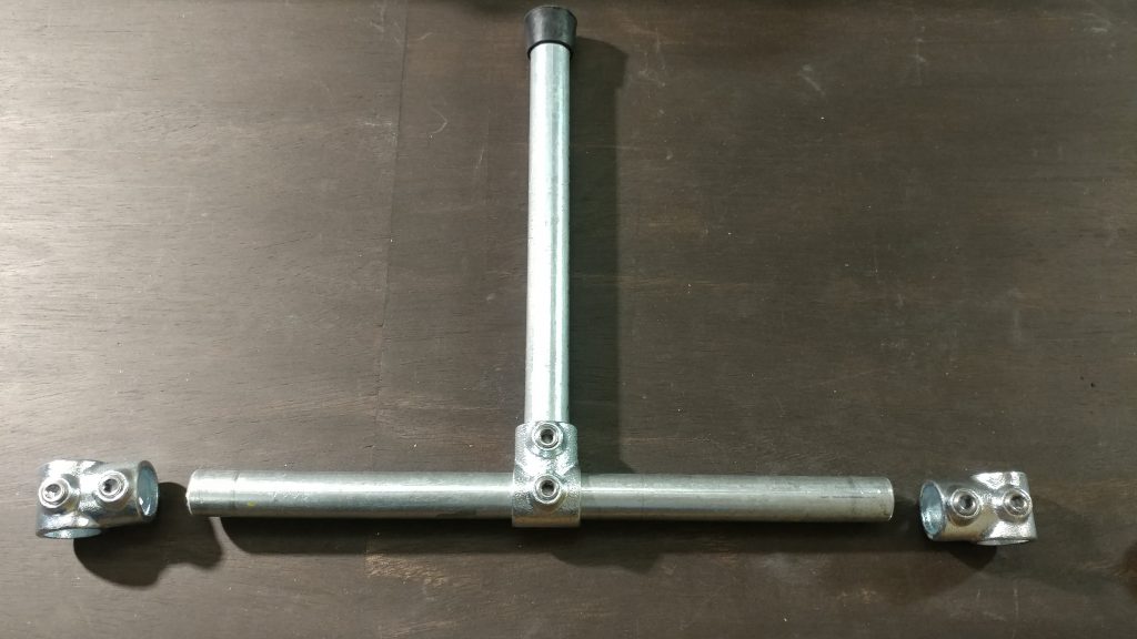
Then I attached three of the tees to the 52″ length of pipe. First I attached one on the end and tightened down the set screw. After that I slid one of the tees over the pipe and moved it towards the center but didn’t tighten it at all. I then added the last tee to this piece and tightened it up.

I then created the rear horizontal brace with the longest piece and three of the single socket tees, with the middle one fitting loosely on the bar.


Once it was all together I fit the loose central tee over the other end of the 6″ pipe and tightened the set screw but only the one that attaches it to the shorter piece.  This meant the large 52″ piece can slide around if I need it to while I’m attaching the legs.

The rear horizontal brace is loosely attached to the rear vertical post.


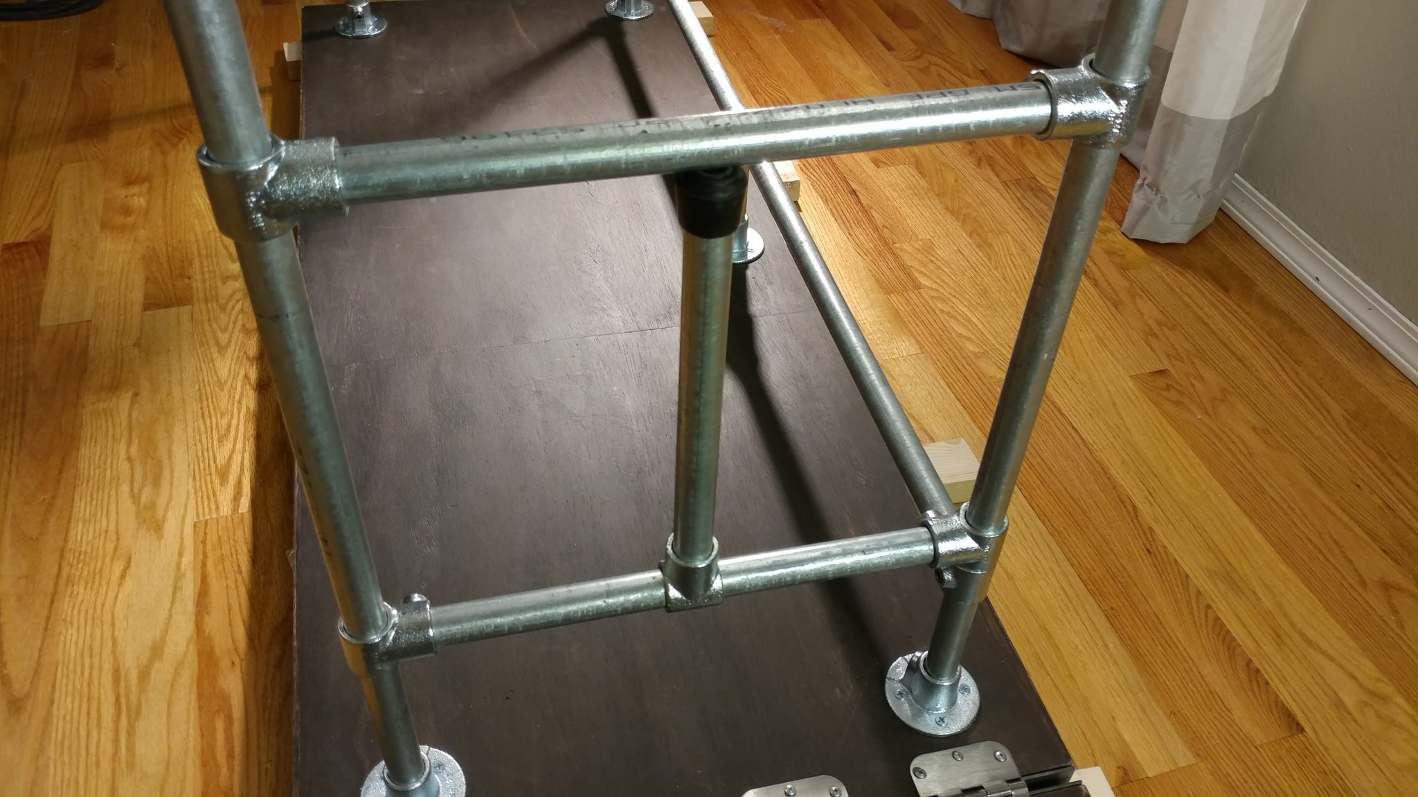
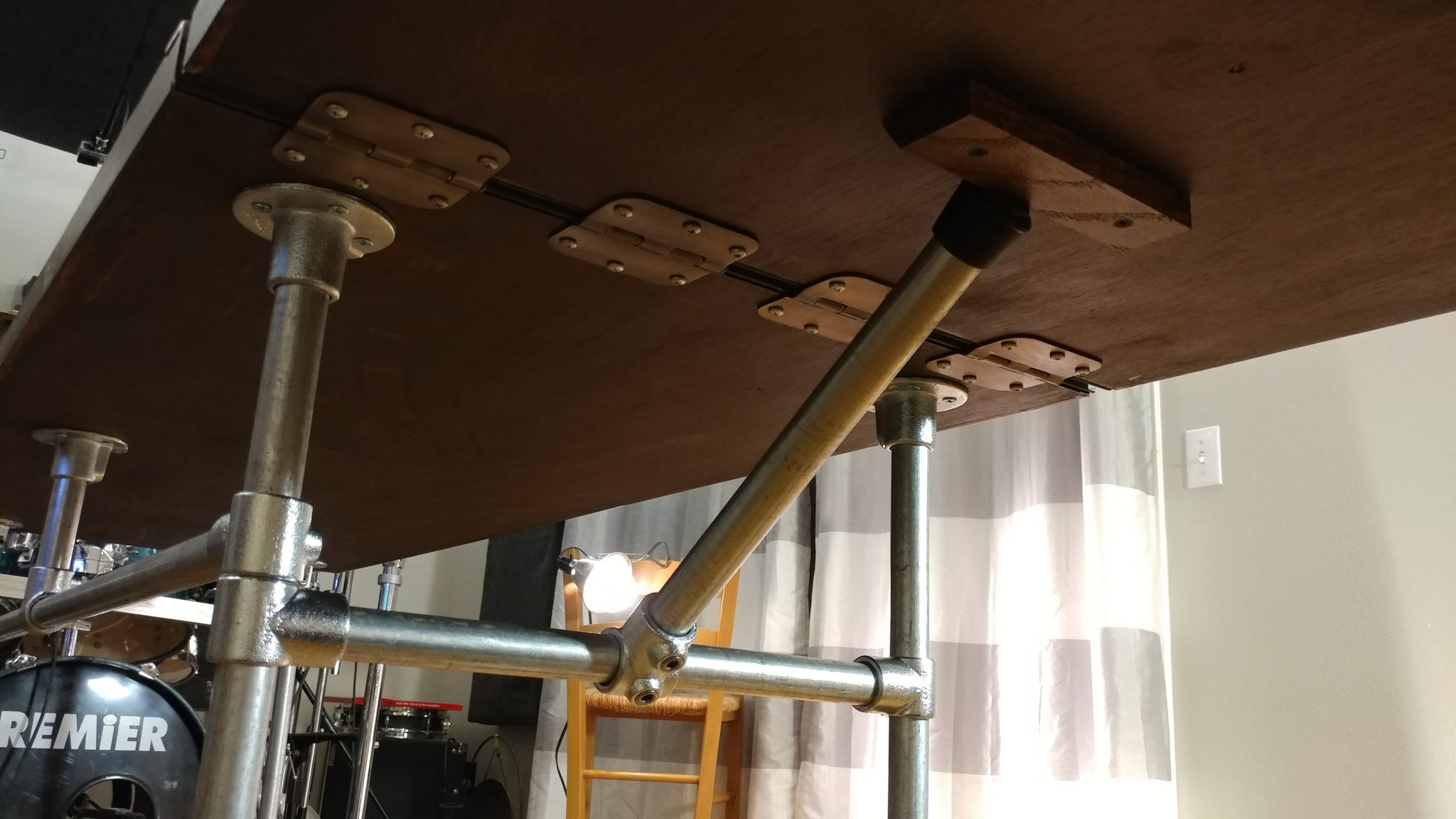
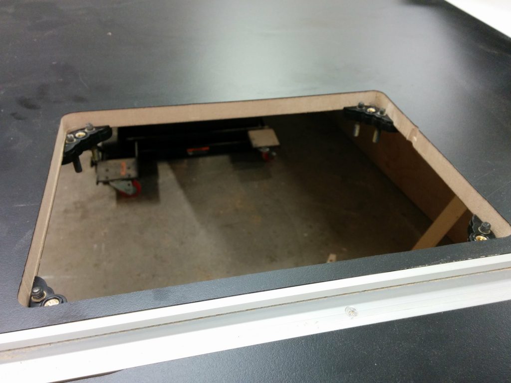
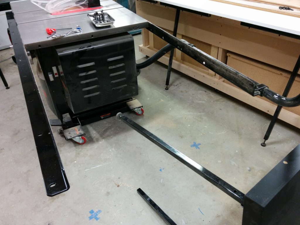
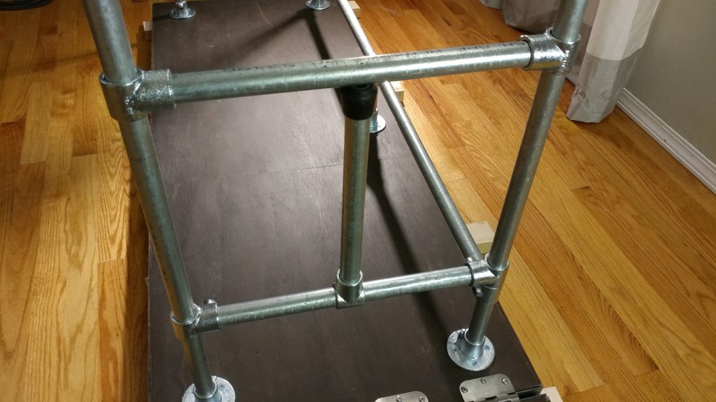
At this point, the only piece of pipe that is secure is the 6″ piece. This let me insert one of the sets of legs into the flanges on the side without the extension wing.  I made sure the legs were square with the bench-top and tightened down the set screws in the flanges. The tee that attaches the rear rail to these legs is still loose.  It’s worth noting that I have all of the set screws one every fixture facing the inside of the desk.  This will make it easier to remove the bench-top from the legs without having to move the bench away from the wall.

I then inserted the legs for the side that doesn't have the extension wing.


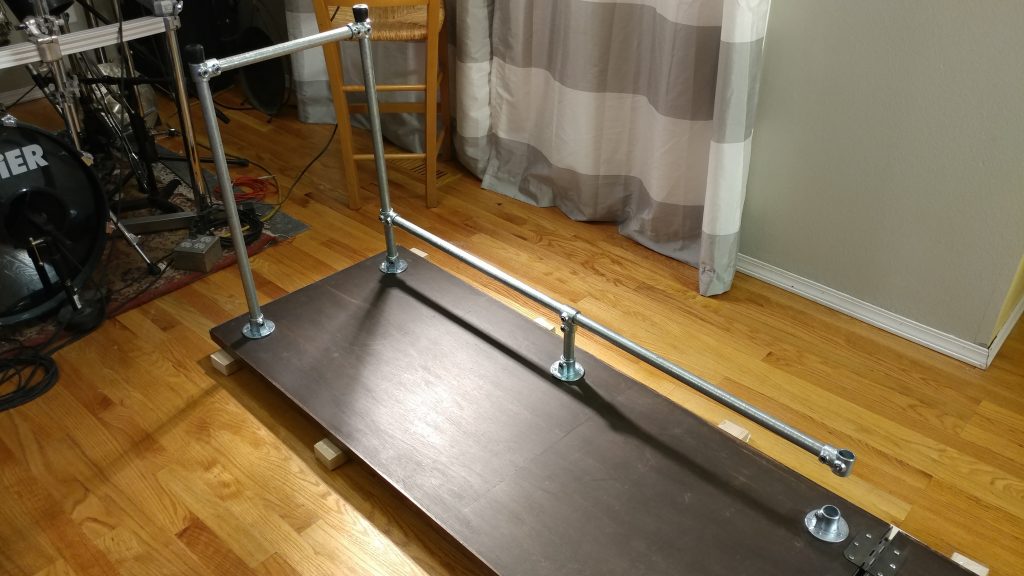
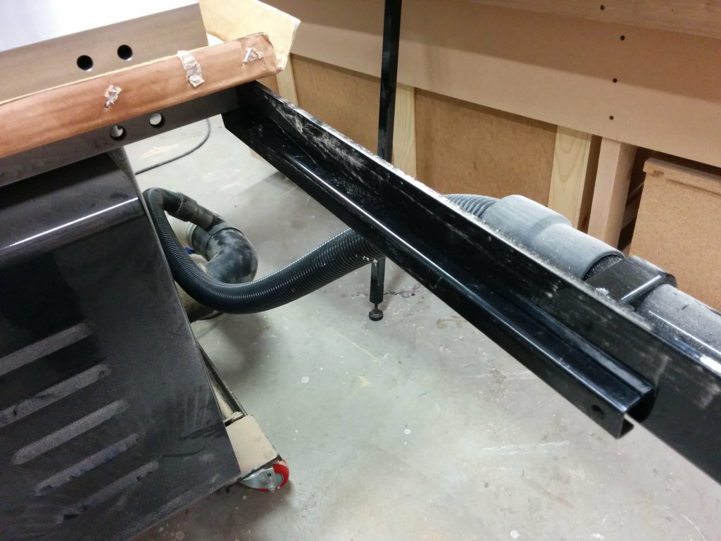
The extension wing support is next. I put this together somewhat similarly to the rear rail except I centered the tee and tightened it down. I also inserted the 12-1/2″ piece with the rubber foot on the opposite end. I tightened this set screw but knew I would probably have to come back and adjust this later. The two tees on the end are kept loose and will remain so.

The extension wing support is made from three of the single socket tees, one of the 16" bars, and the 12-1/4" bar with a rubber foot on the end.


The extension table support is then slid on to the other set of legs. To make attaching it easier, I temporarily tightened the set screws for the tees that attach it to the legs.

The extension wing support is loosely attached to the remaining leg assembly.


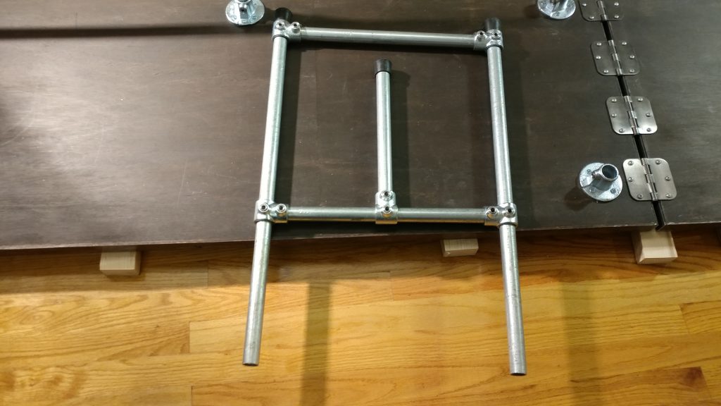
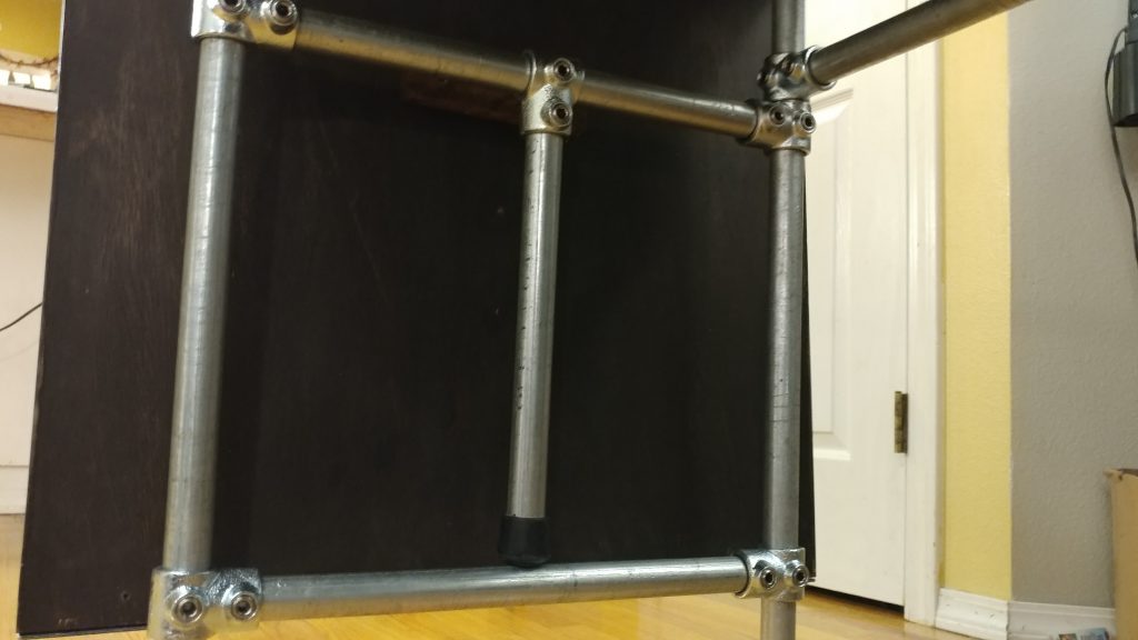
This leg assembly is inserted like the opposite one. Make sure it is square to the bench-top and tighten the set screws on the flanges. Then, I ensured that the rear rail was the same distance from the underside of the bench-top at either end and tightened the set screws on the tees at each end of the rear rail.

The second leg assembly is attached. Everything is tightened down except for the extension wing support.


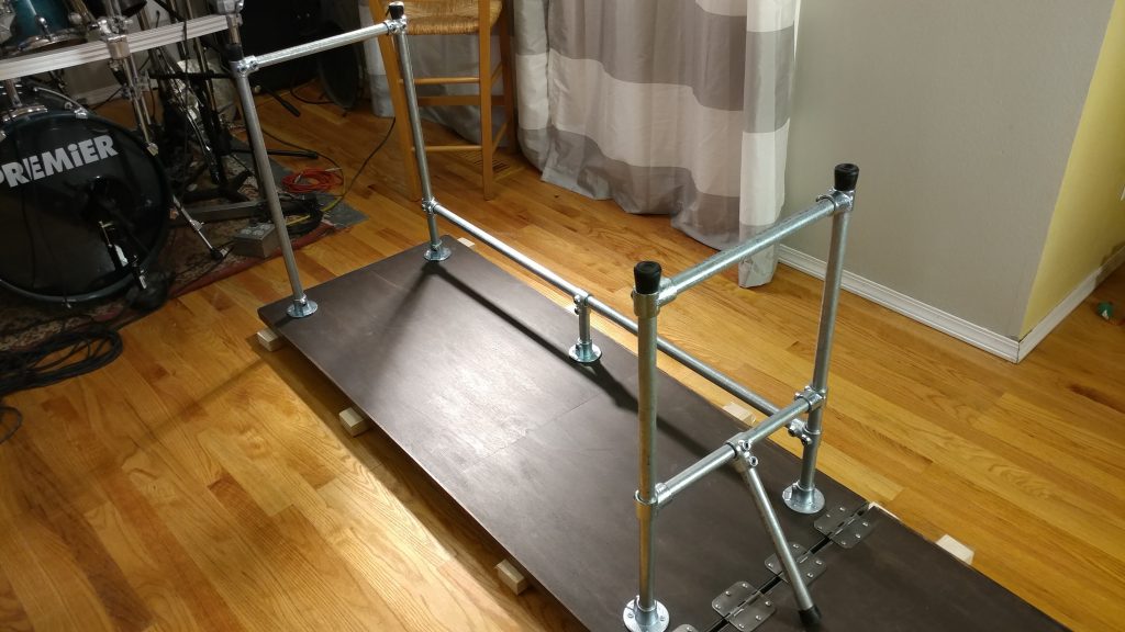
Then I loosened the set screws on the tees that attach the extension wing arm support to the legs and slid them down so the rear tee rested on top of the tee on the rear rail. I tightened it down and set the opposite tee on this piece to the same height and secured it as well. I then lowered the horizontal brace so it rested on the rubber foot of the extension wing arm and tightened it down. Once that was in the correct position, I took a measurement and duplicated this position on the horizontal brace on the other legs.

The extension wing support is raised to the point that the rubber foot presses on the lower horizontal brace, then the set screws that attach the tees to the vertical legs are tightened.


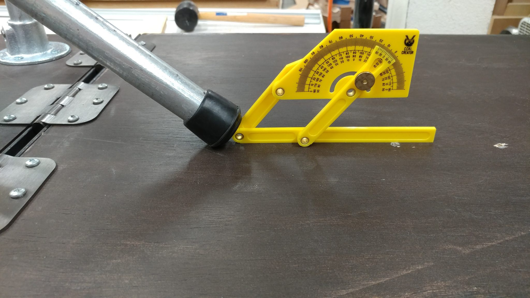
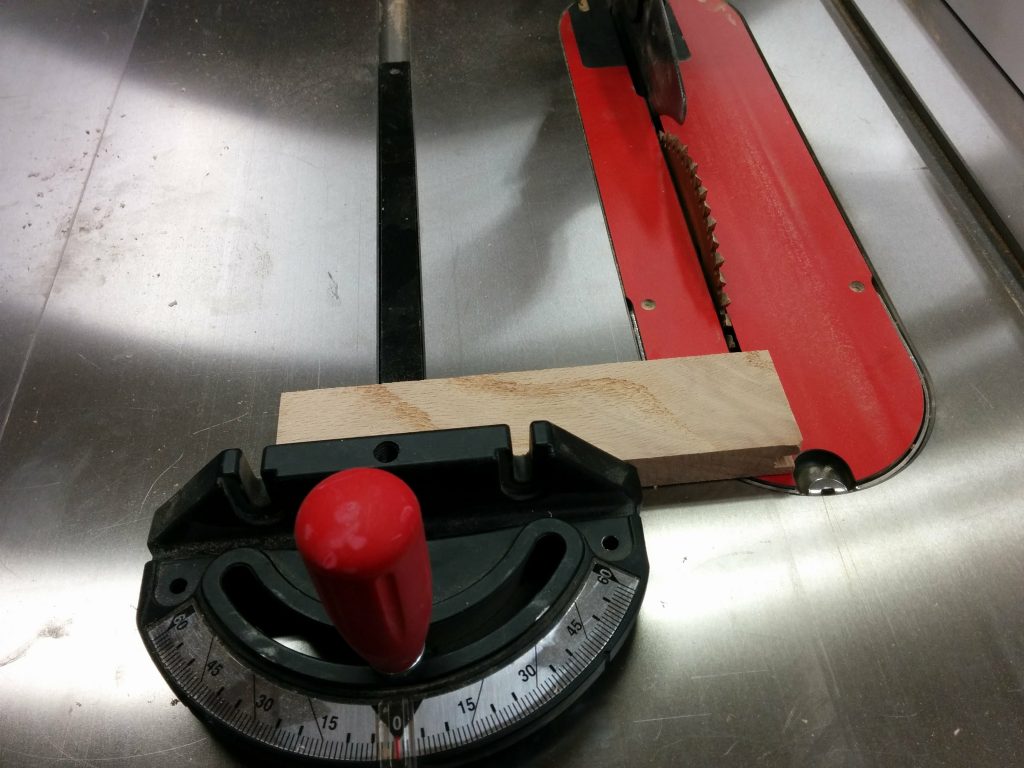
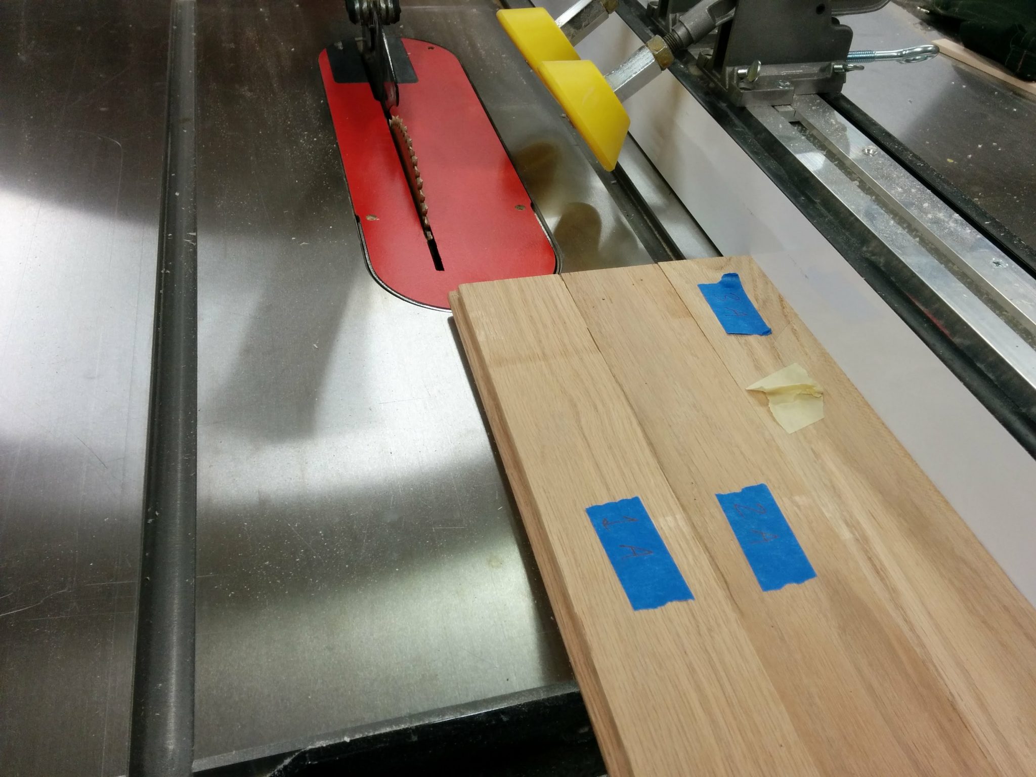
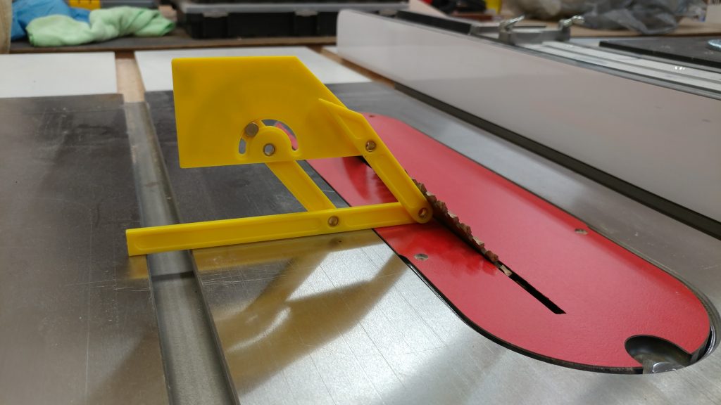
Since I didn’t tighten the set screws that hold the extension wing horizontal brace to the front and rear legs, this whole mechanism can swing up and support the wing.  I needed to make a wedge for the leg to press against.  After ensuring that the bench-top pieces were co-planar, I swung the arm down and measured the angle.

The angle of the foot is measured at about 45-degrees.


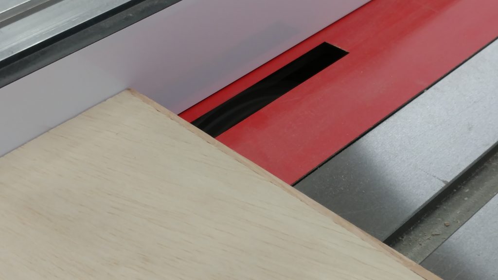
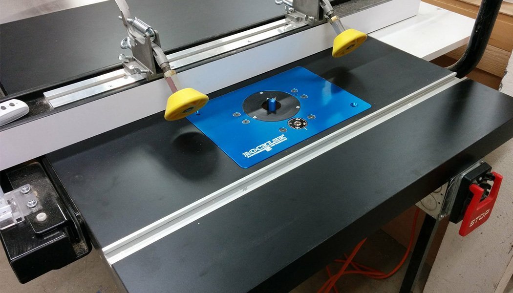
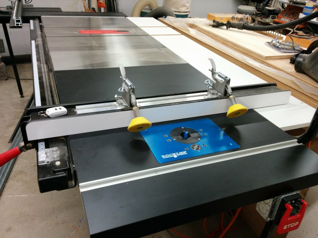
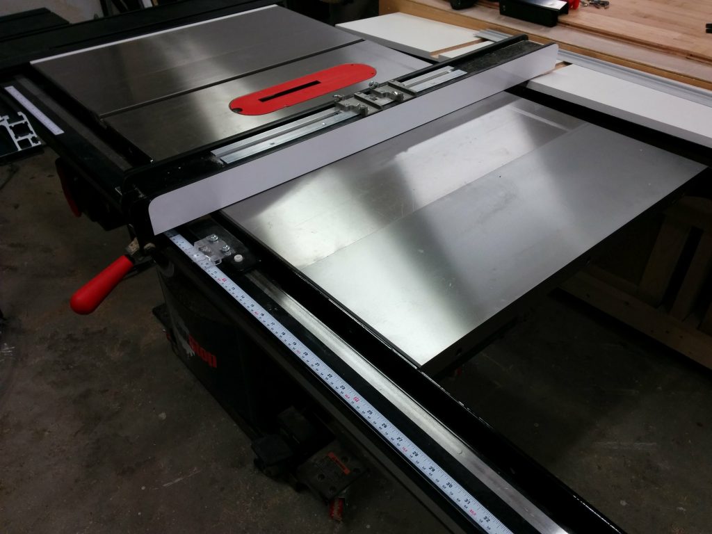
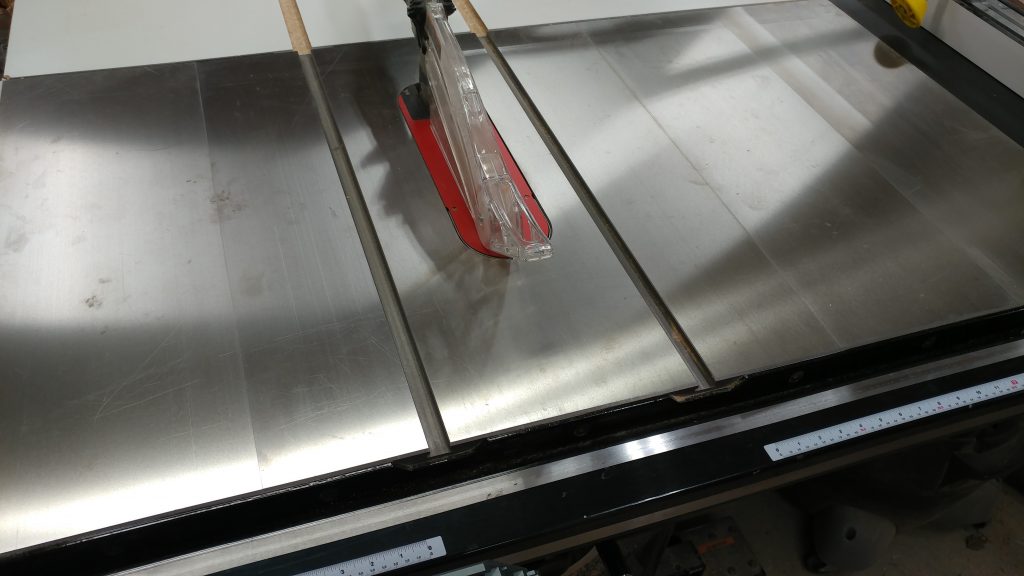
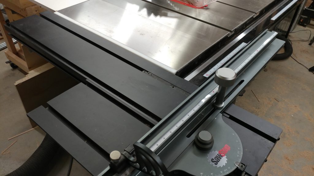
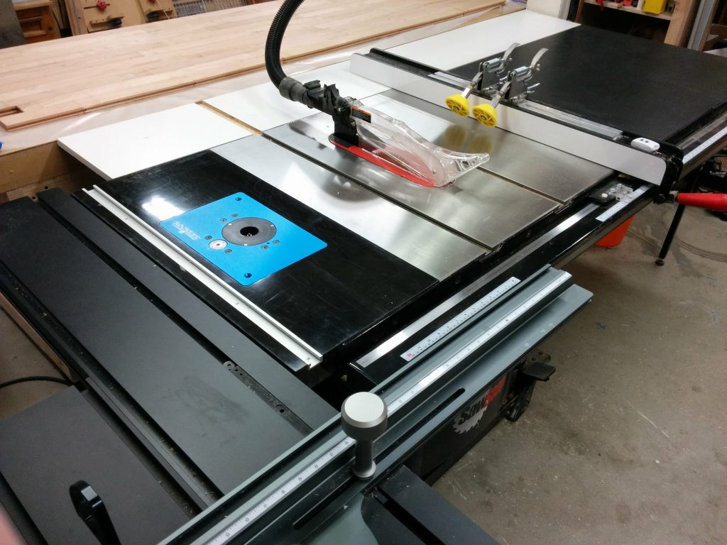
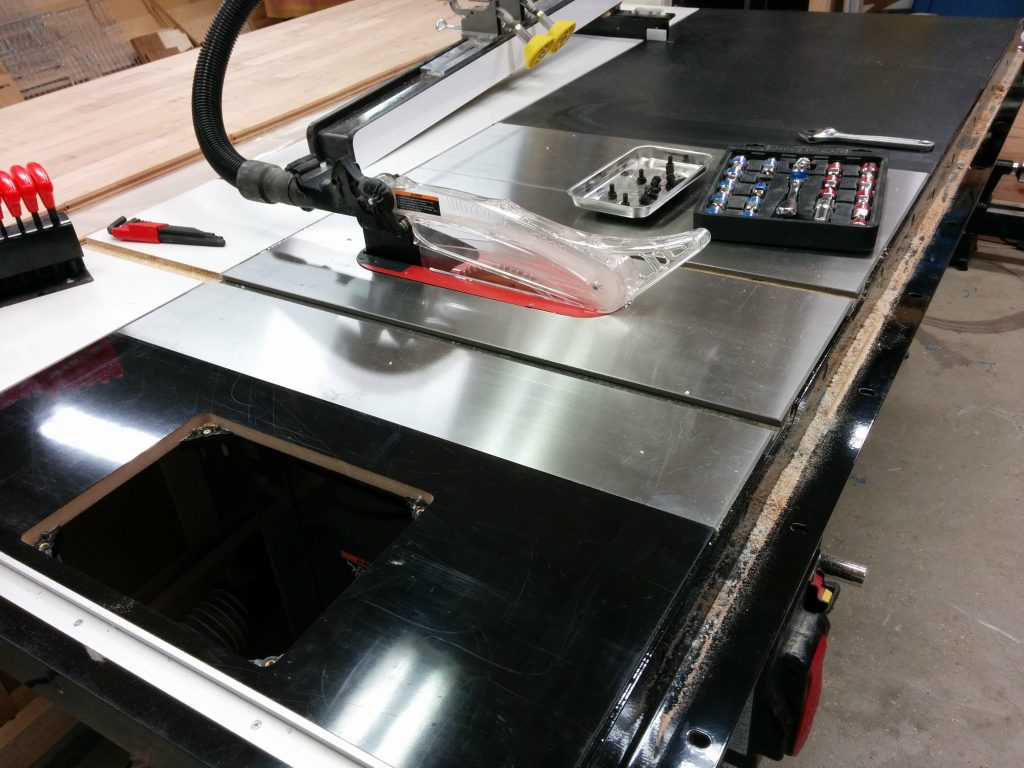
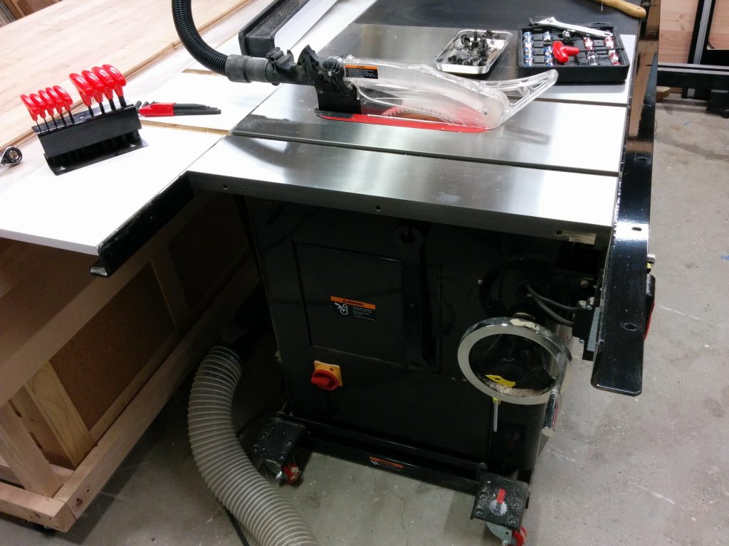
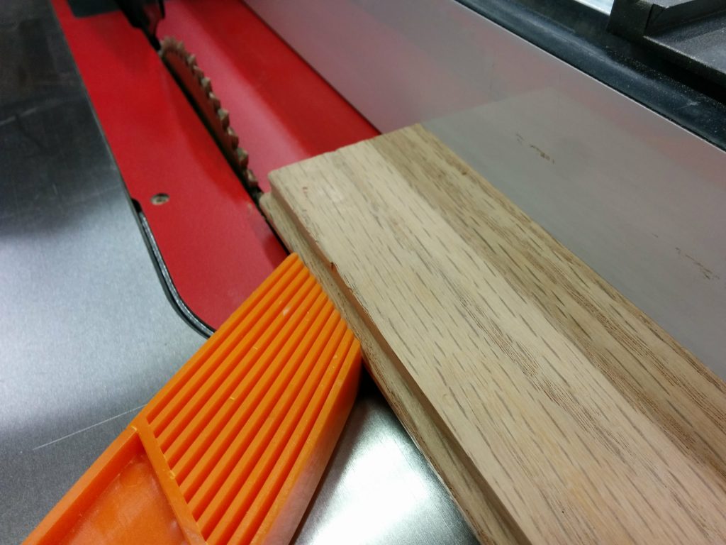
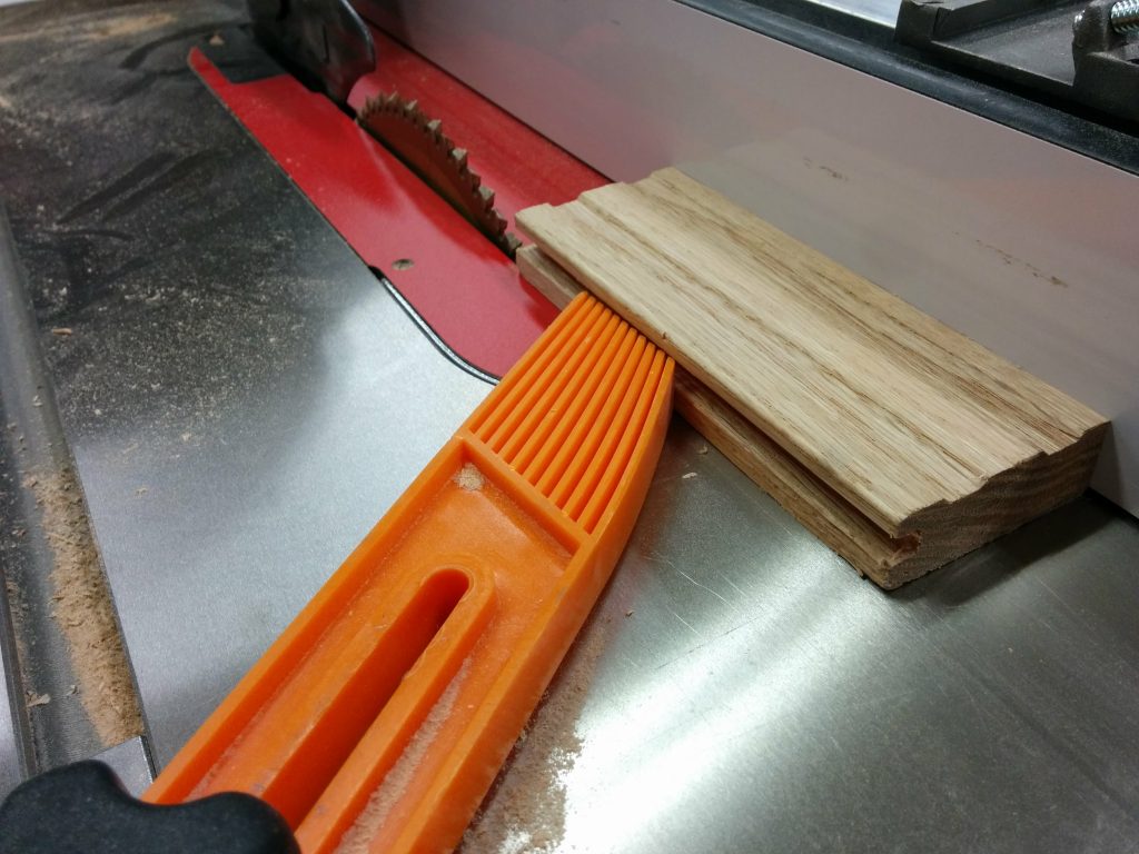
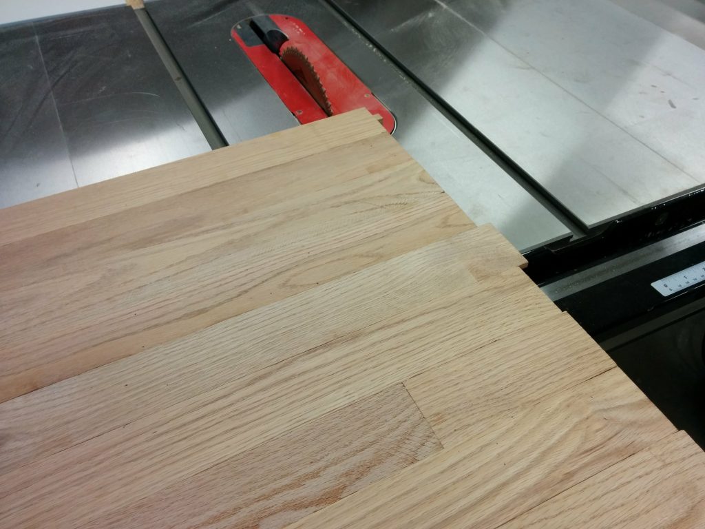
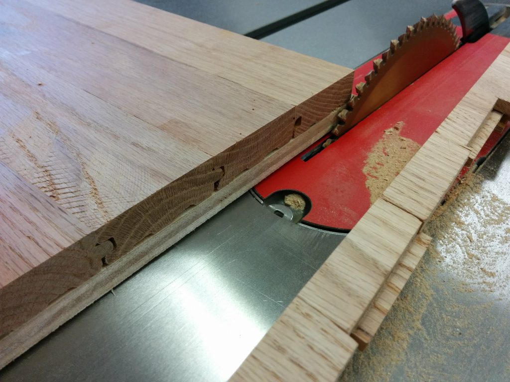
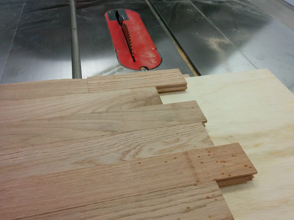
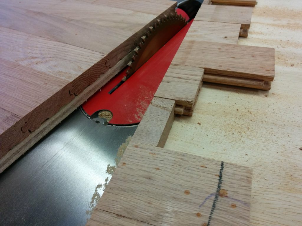
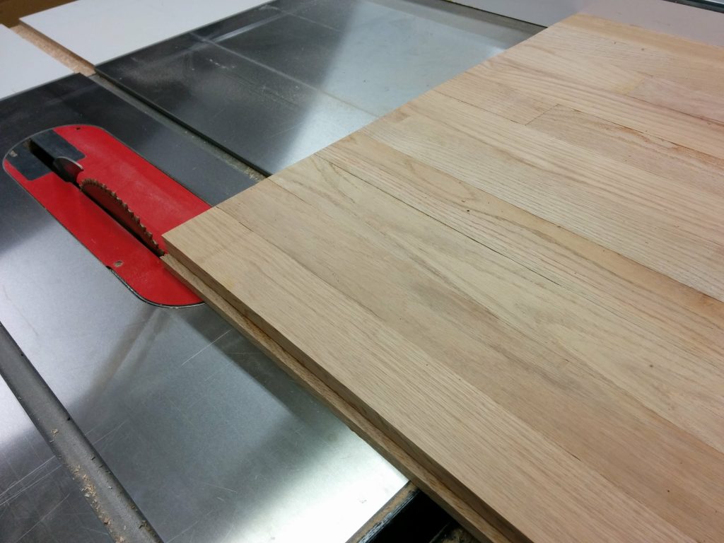
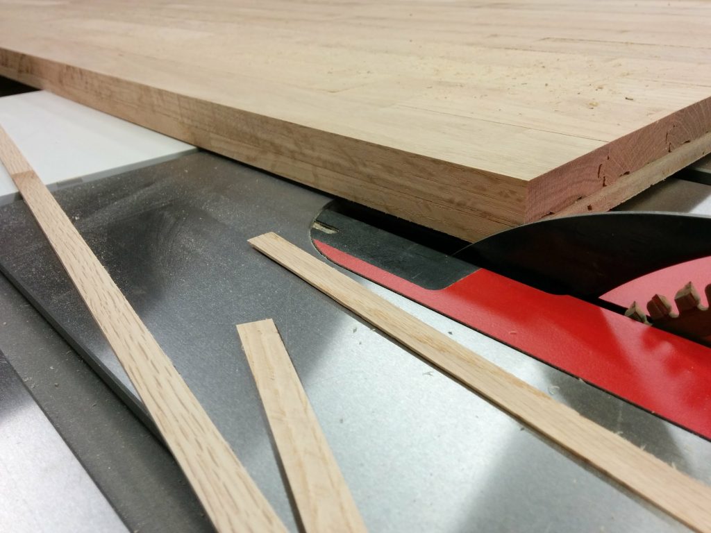
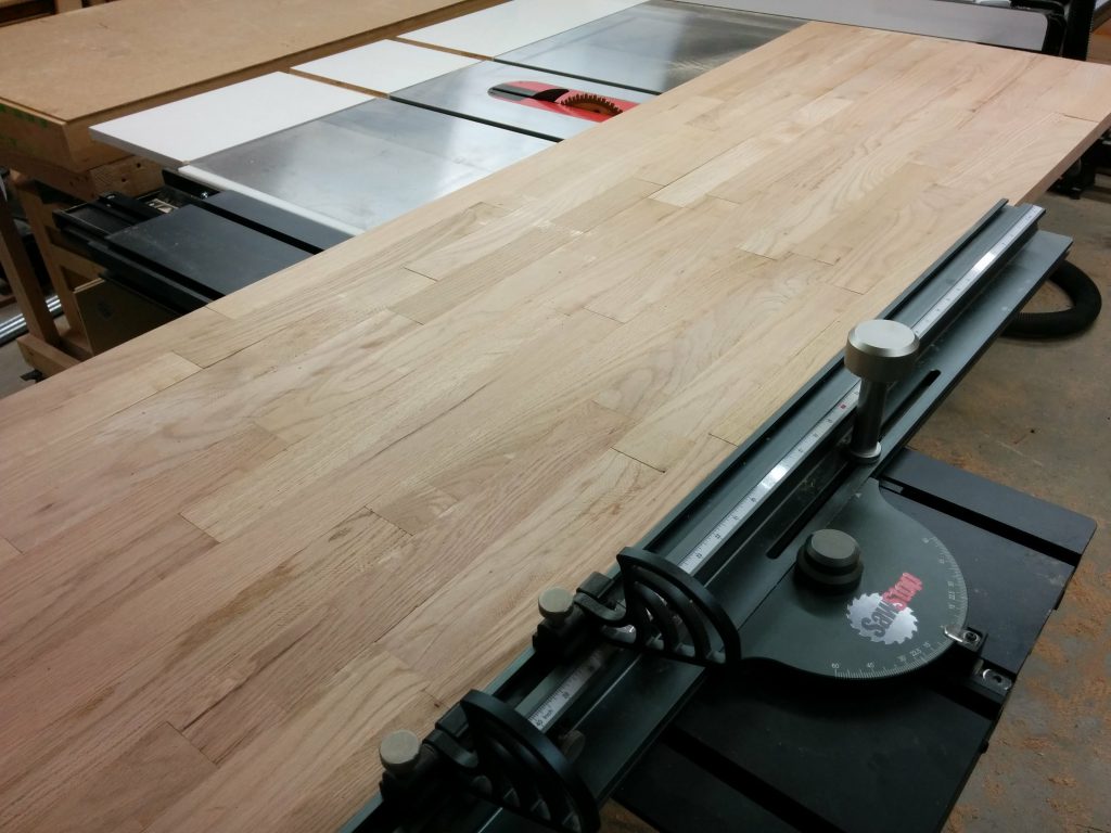
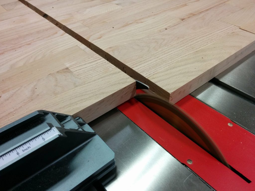
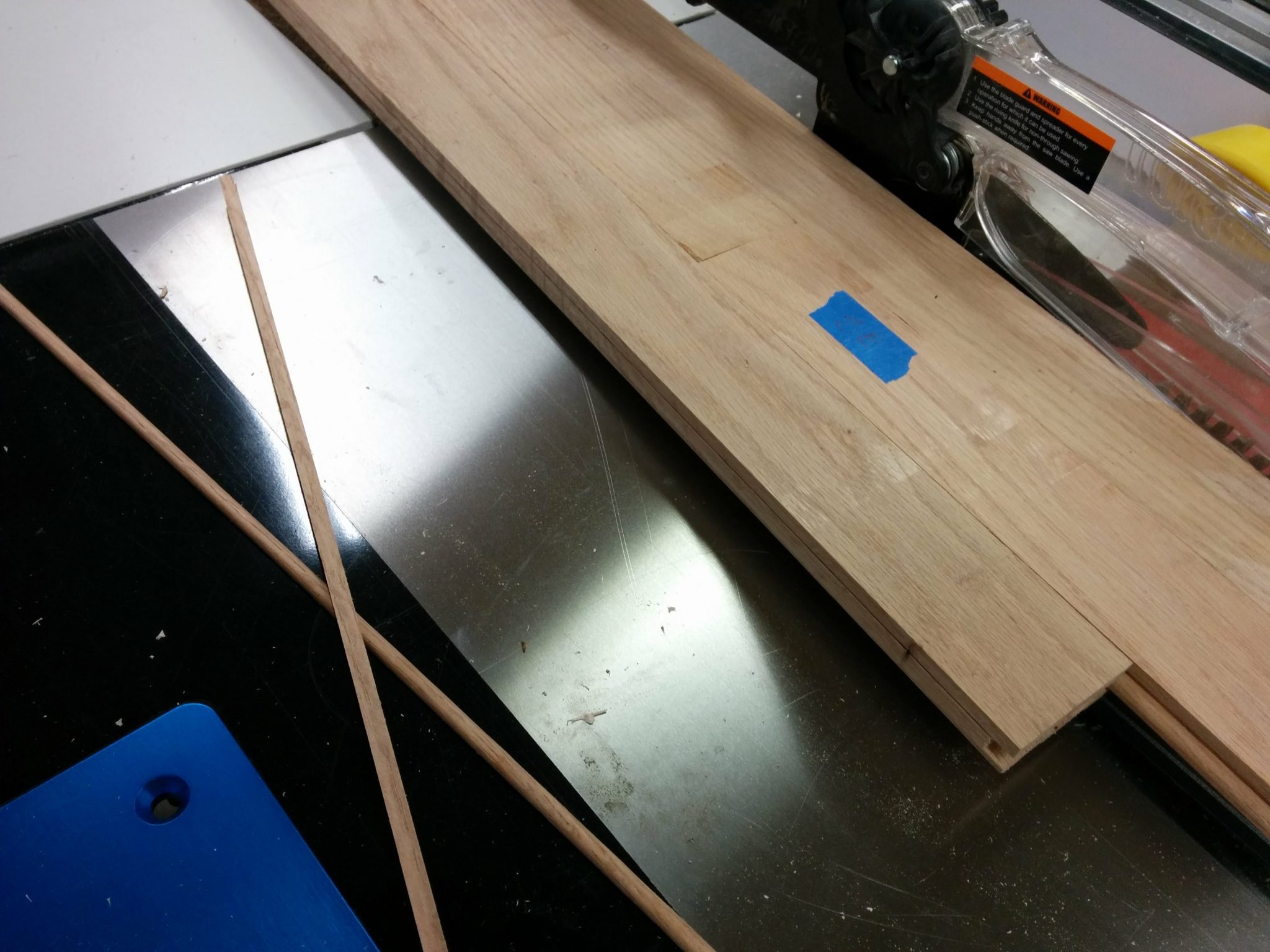
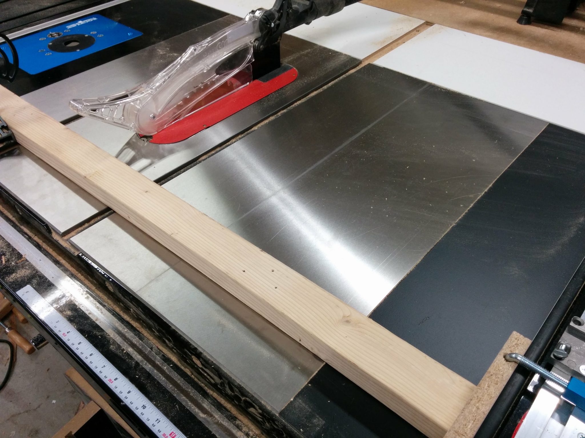
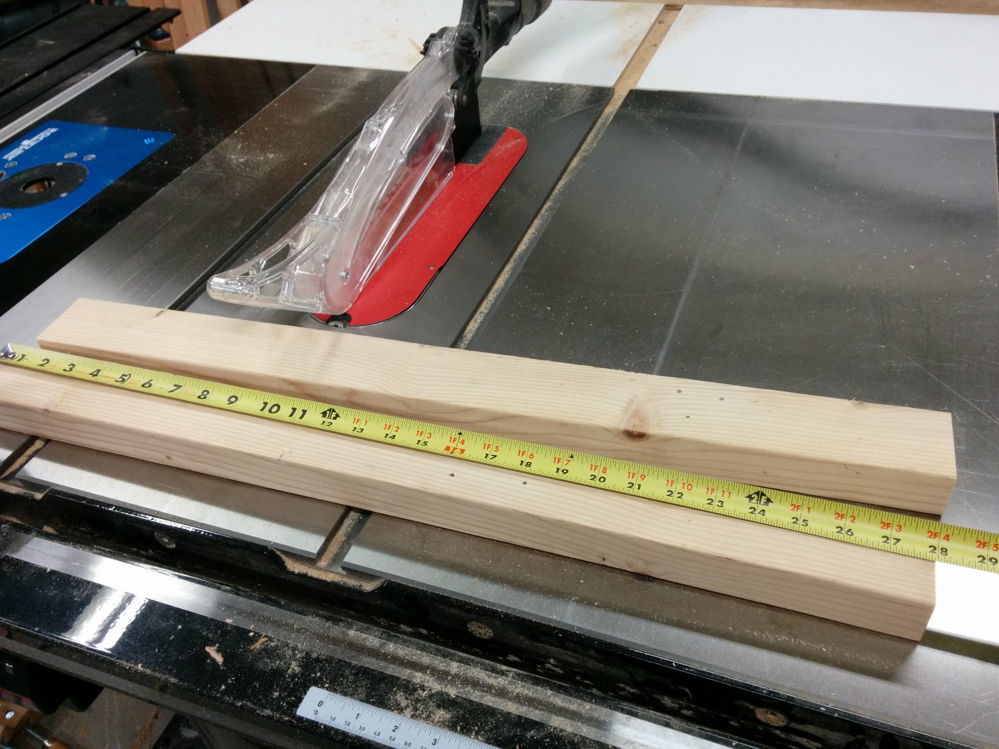
I then transferred that angle to the table saw.

This angle is then transferred to the table saw.


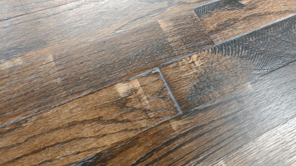
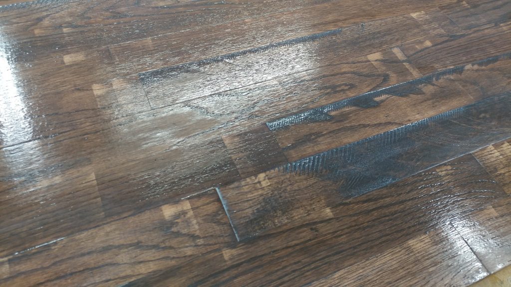
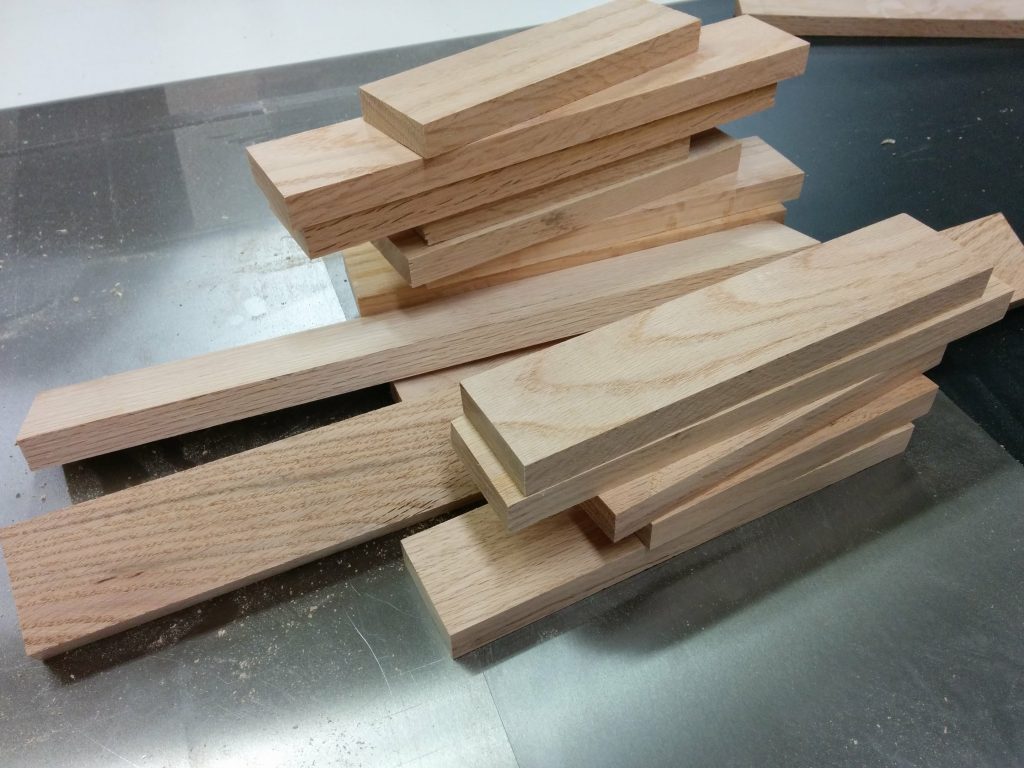
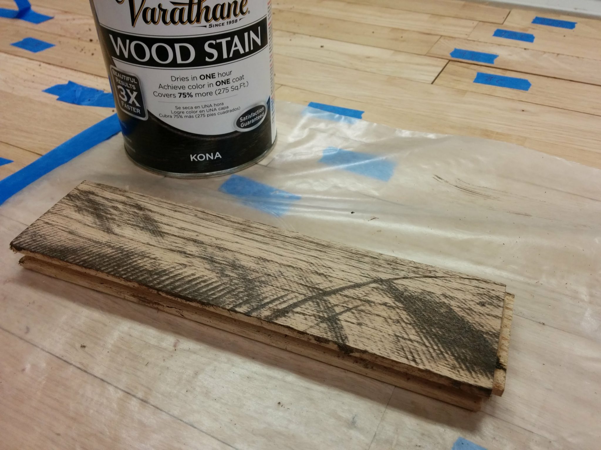
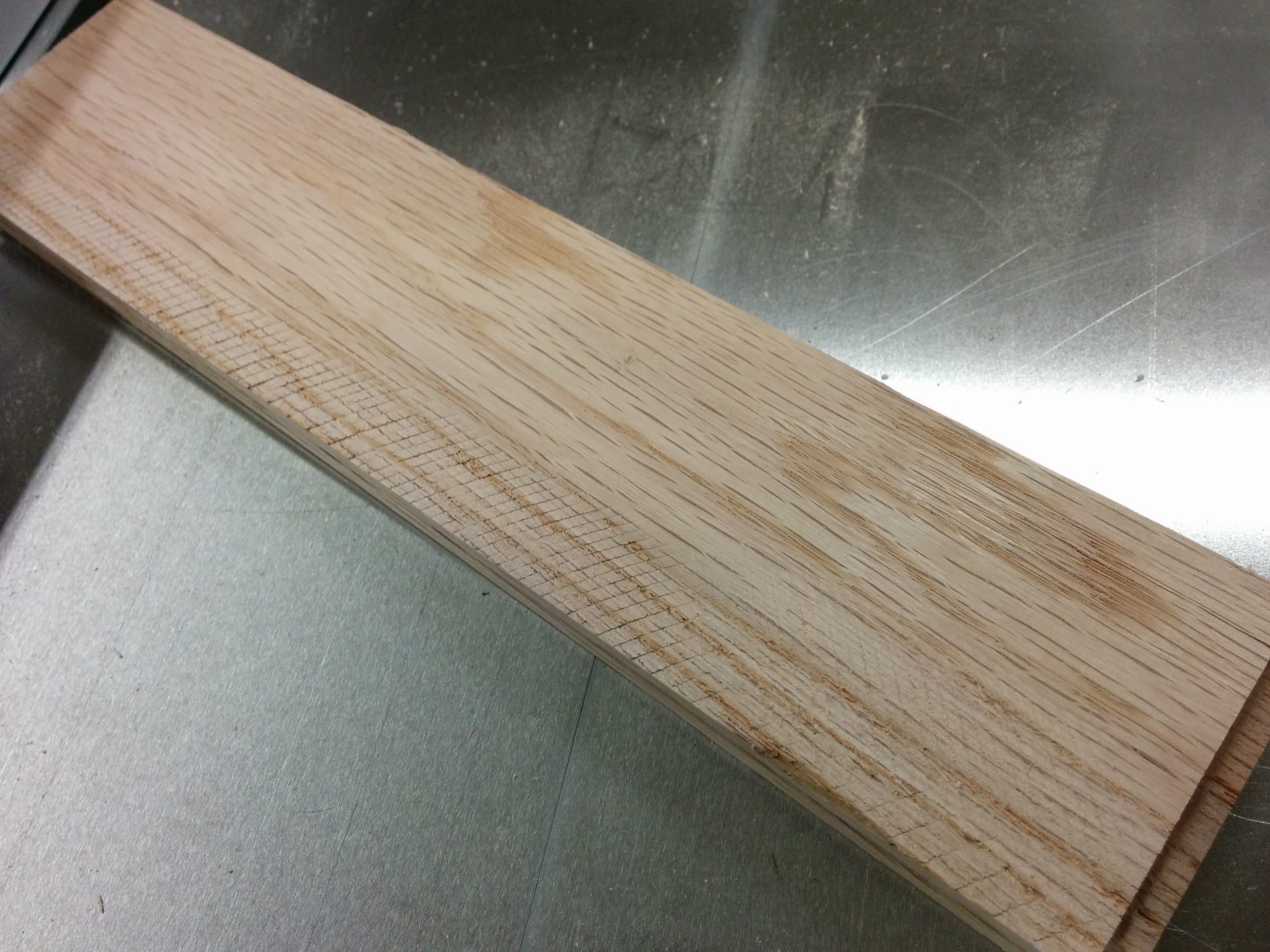
I cut a bevel of that angle on a scrap piece of oak flooring that was left over from this same project.  I left this piece longer than I needed in case I need to try attaching it in different areas.

I took a scrap piece of oak and added that angle to one edge.


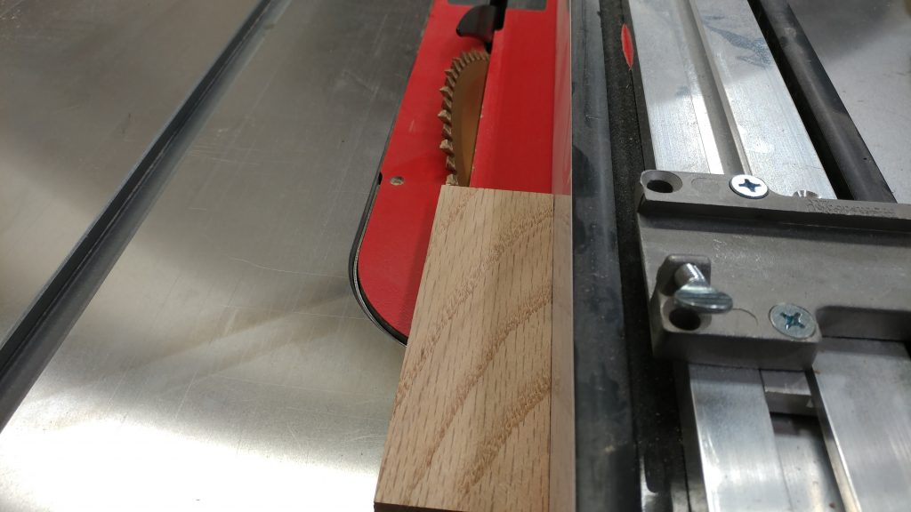
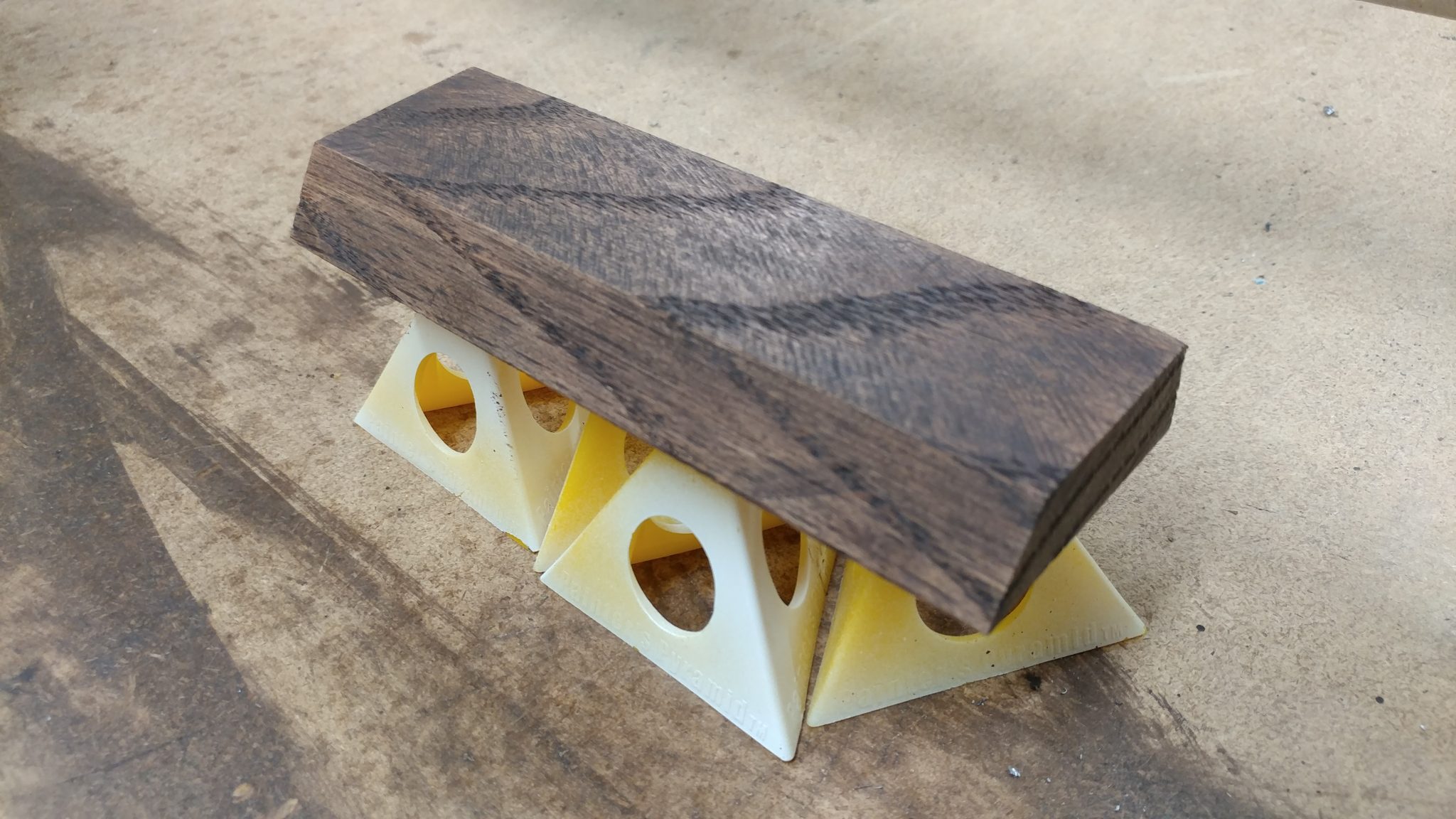
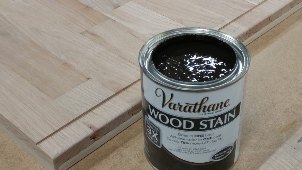
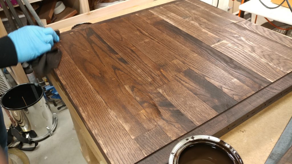
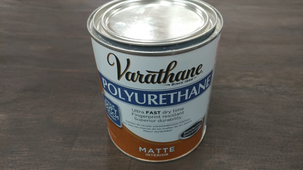
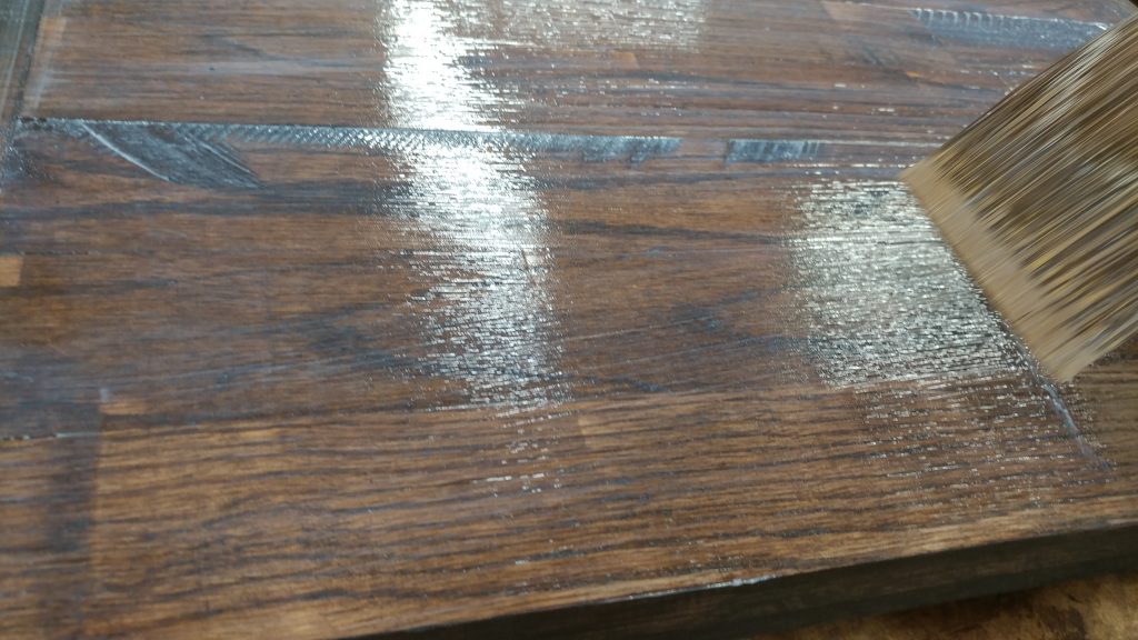
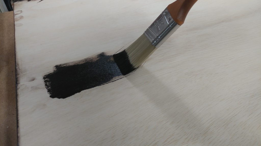
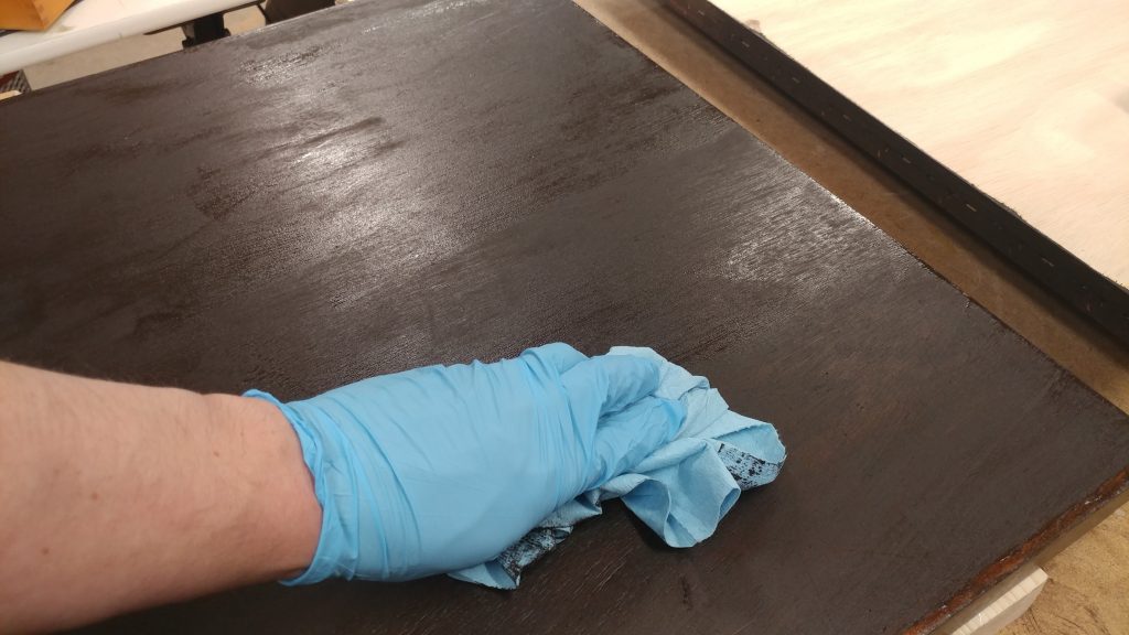
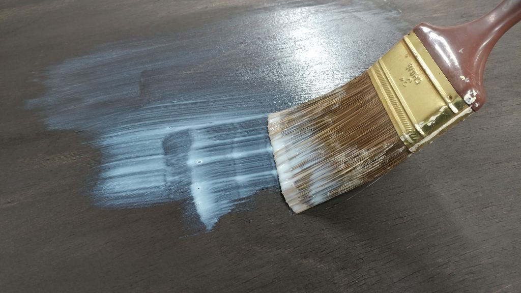
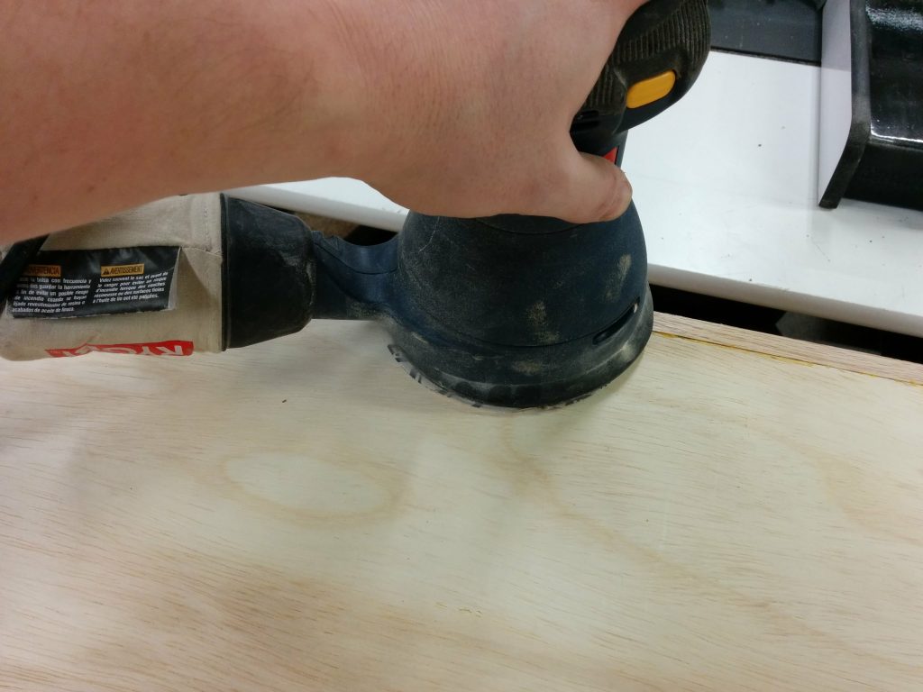
Once it was cut, I applied a coat of the same stain that I used on the rest of the desk and a single coat of polyurethane.

This piece was then stained and a single coat of polyurethane was applied.


I pressed this piece firmly into the foot of the extension wing arm and secured it with drywall screws. I didn’t glue it in case I wanted to make any adjustments.

Pressing the support firmly into the foot, I secured it to the underside of the extension wing with some drywall screws.


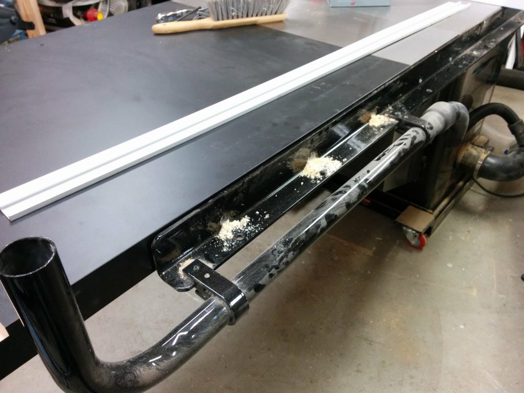
I set the bench upright and tested it out. The wing sagged a bit but rather than remove the wooden wedge and move it forward, I loosened the set screw that holds this arm in place and slightly extended the arm a bit. I tightened the set screw again and made sure the wing was flat with the main table.

The support arm holds the extension wing up and is adjustable because of the set screw on the tee.


If you want to lower the extension wing, you simply lift the extension wing slightly and the support arm swings down out of the way.  The rubber foot on the end grabs the bottom brace and friction locks it in place.
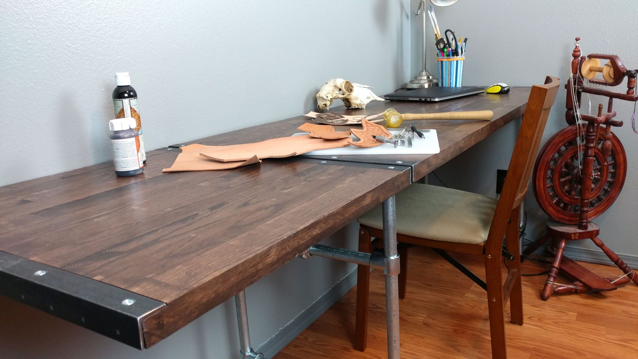
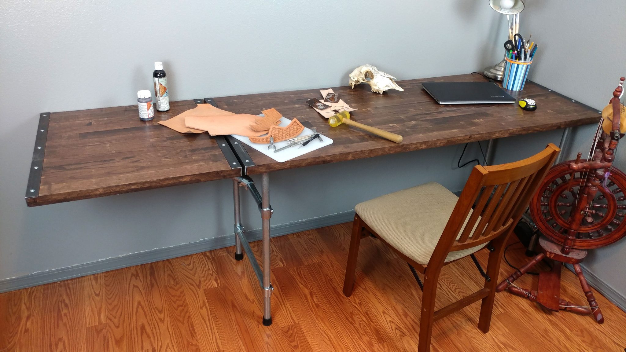
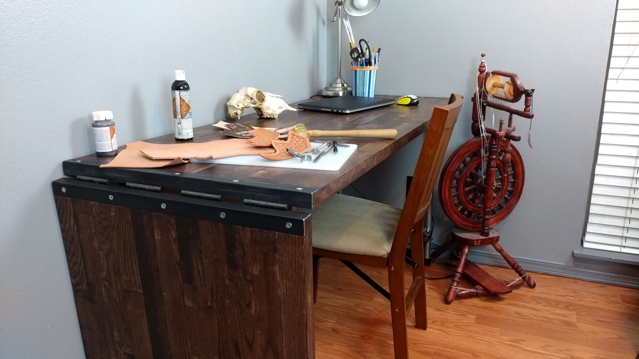
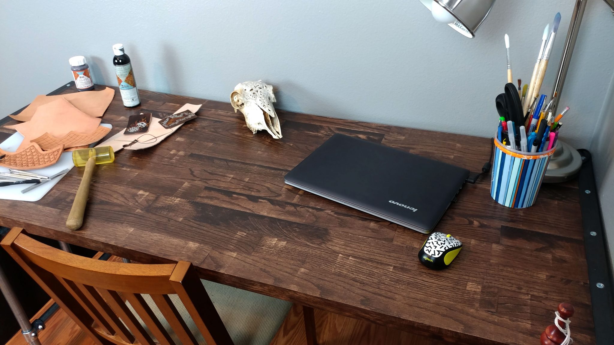
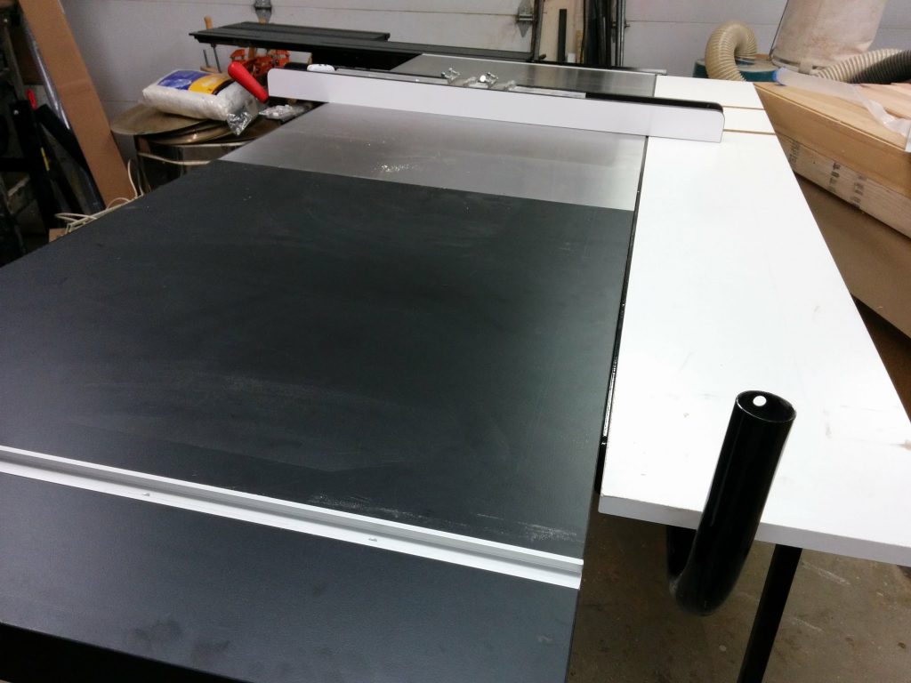
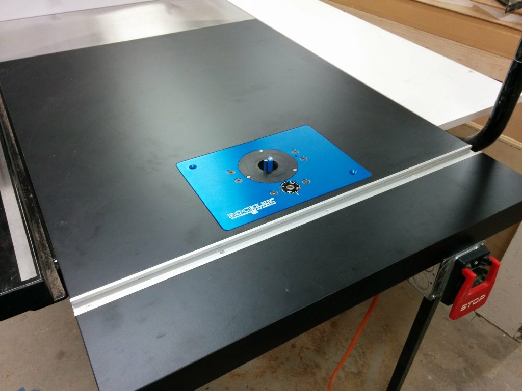
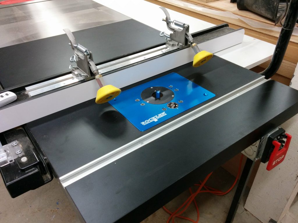
When not in use, the support arm swing down and out of the way.


All finished.


It’s time to call this project done.  My wife and I moved it up to her studio and I gave her a few days to test it out.  So far it seems to be very sturdy.  I have plans to add a shallow drawer or two but I’m going to let her use the bench for a bit to see if that is something that she really needs.

Finished desk with the extension wing in use.


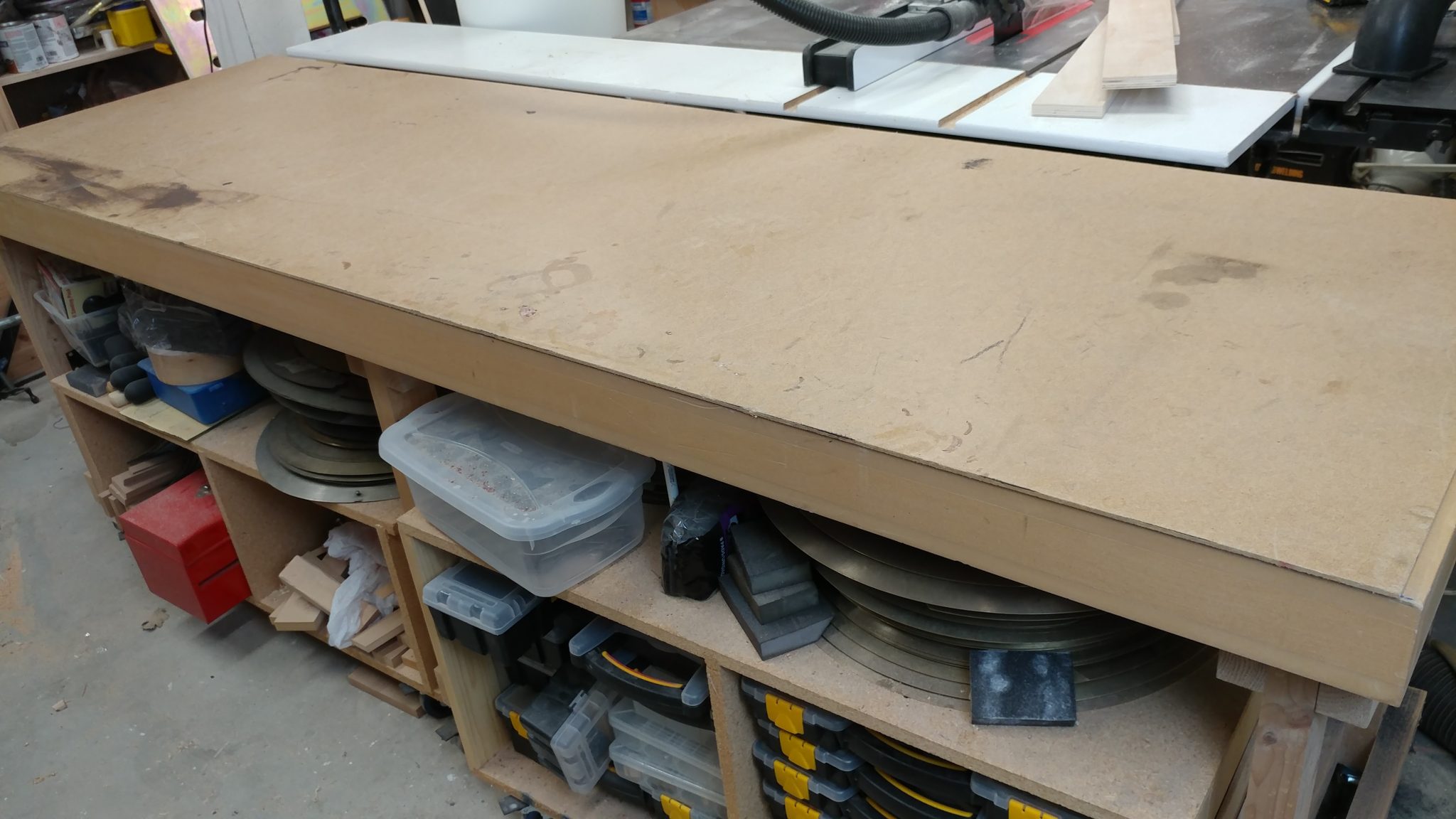
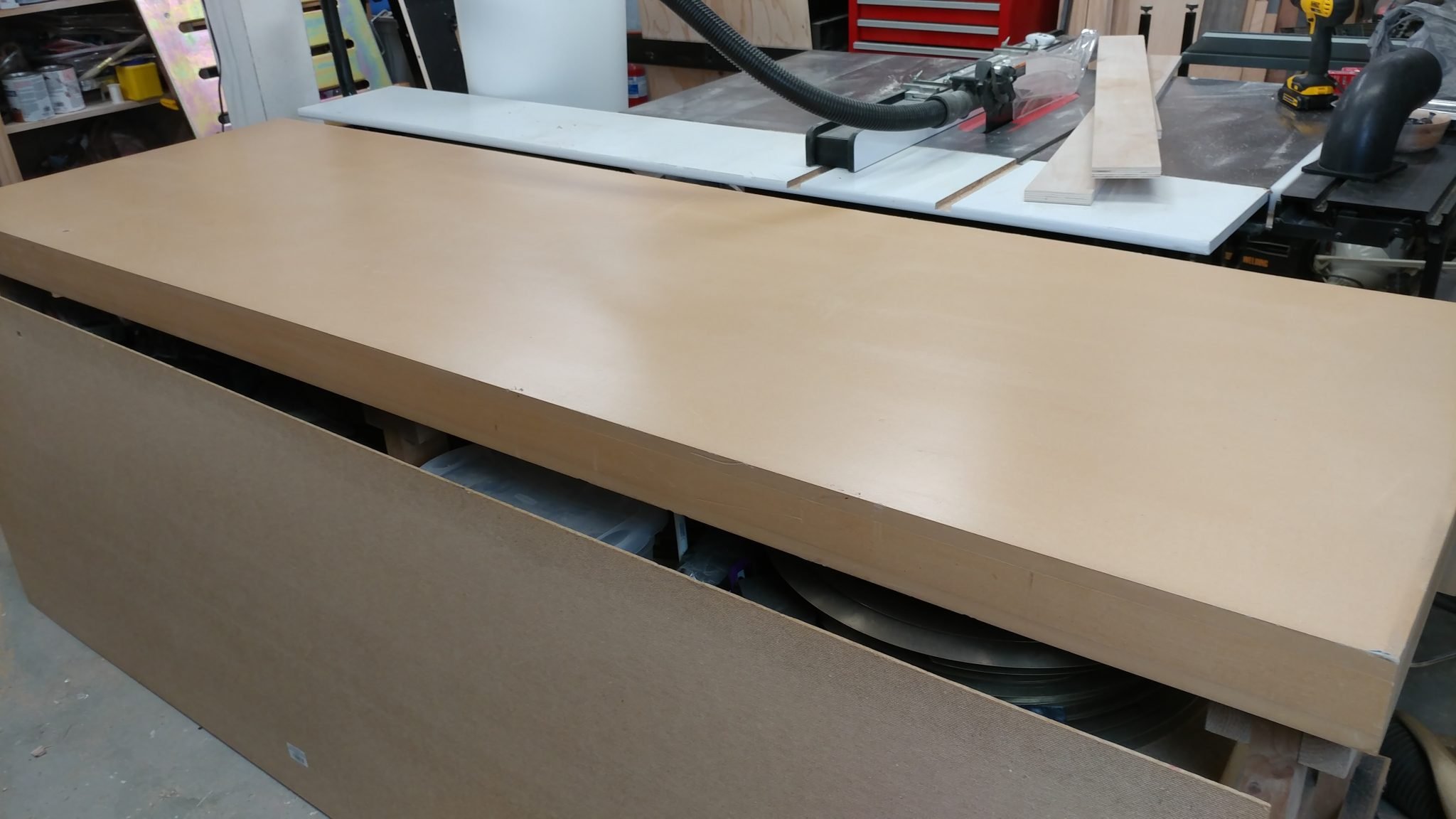
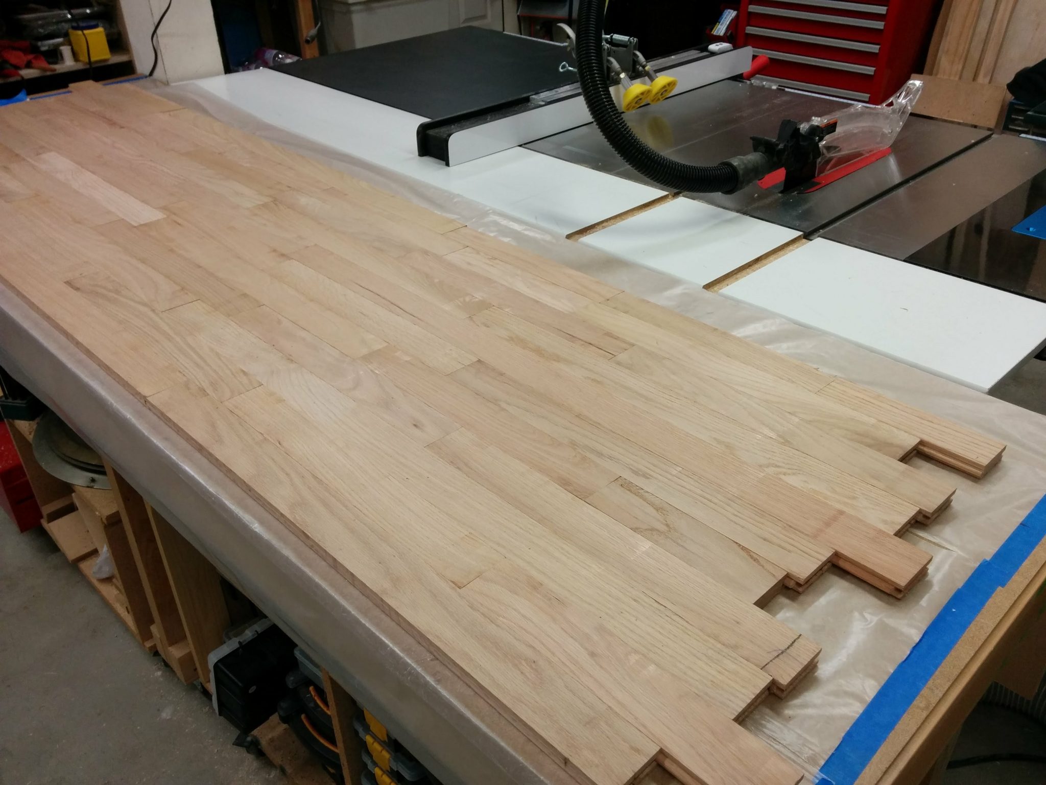
It really does provide a lot of work surface.  The overall dimensions of the work surface is 24 ½” x 83 ¼” when the extension wing is up.

The extension wing provides a lot of work surface.


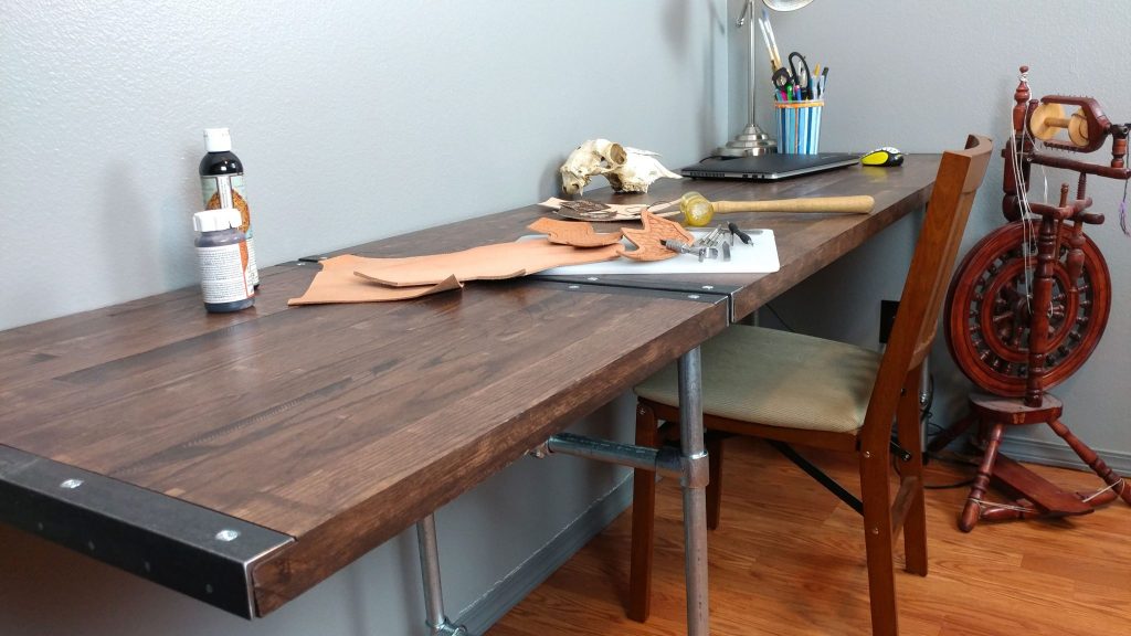
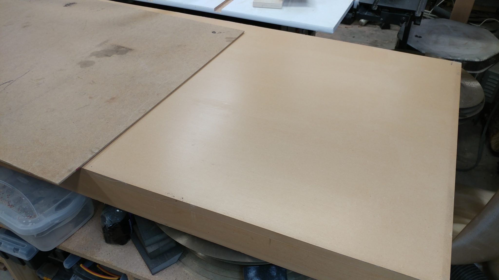
When the extension wing is not needed, it easily folds out of the way creating a work surface of 24 ½” x 60 ¼”.

The extension wing easily folds out of the way when not in use.


This gives her the space to work on her computer while still having her projects set up.

My wife is making good use of all this work space.


Please let me know if this helped you in any way or if you have any suggestions for how I could have done this differently.  I’m also planning on a few more projects along this same style so if you have any suggestions, please let us know in the comments section below.  I’d love to hear from you.  Also, please consider signing up for my mailing list to be notified of future articles. I am also available on social media. Stop by and say ‘Hi’. I can be reached at the links to the right.

<< Back to Workbench: Part 6 – Finishing the benchtop
<< Back to Workbench: Part 5 – Cutting the benchtop to size
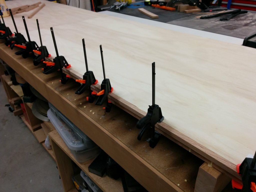
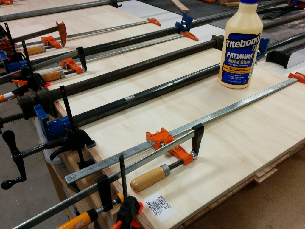
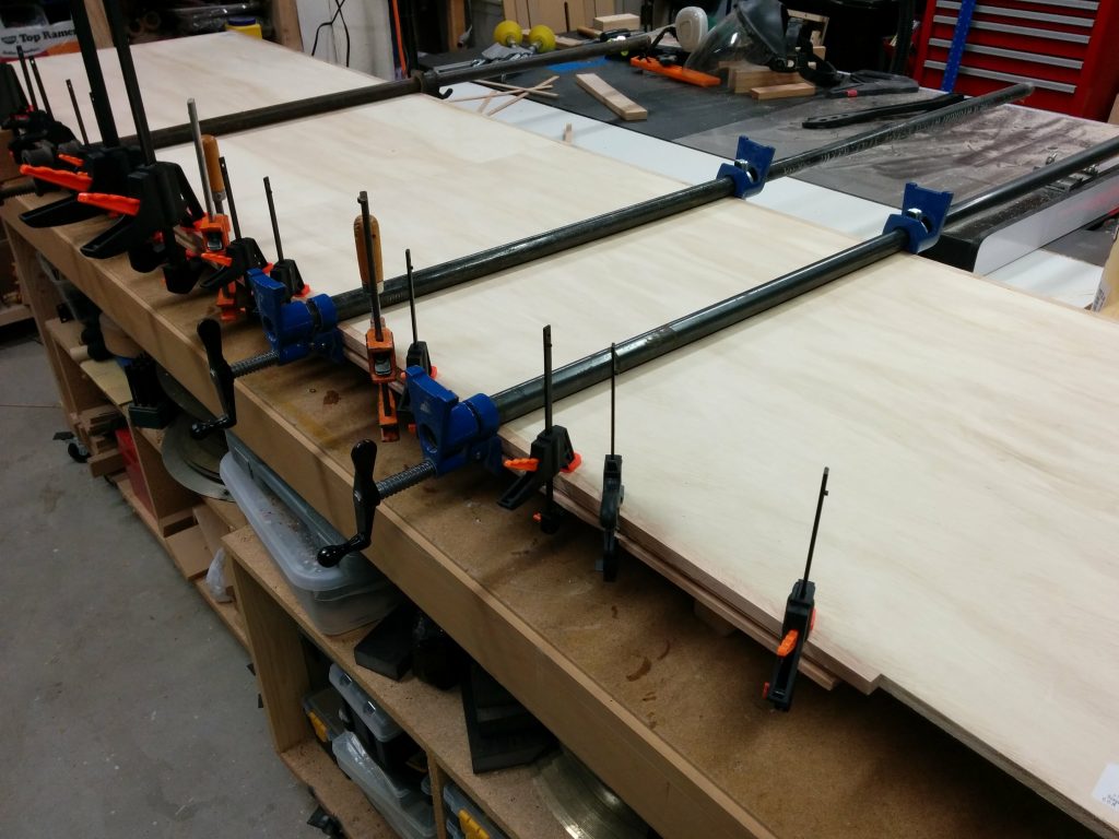
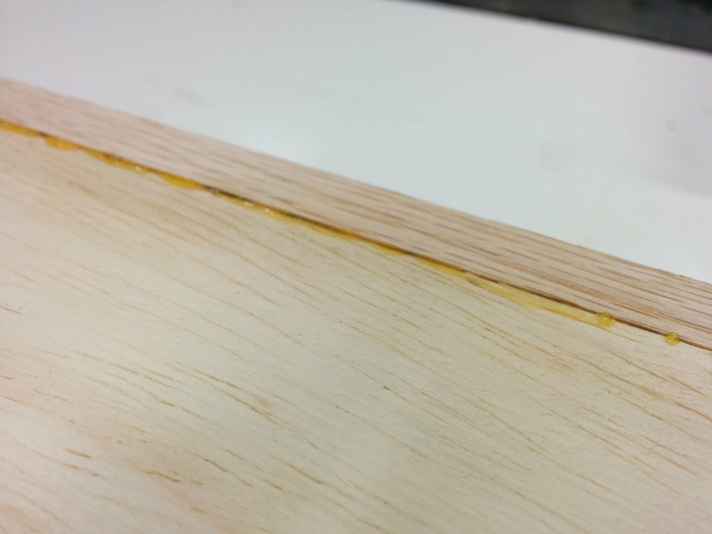
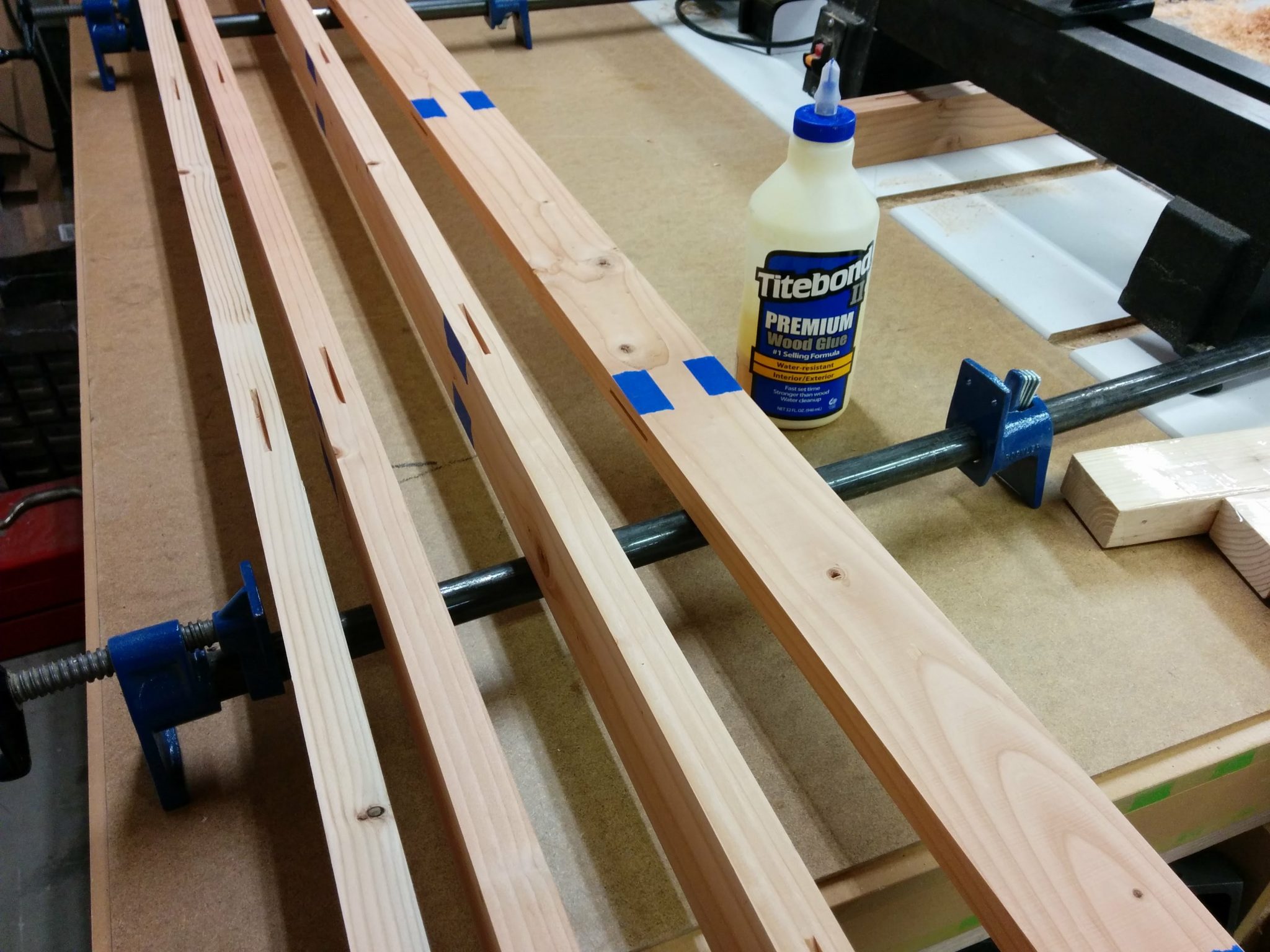
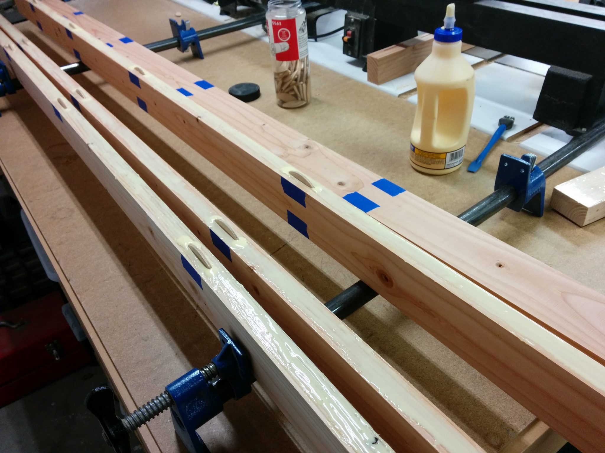
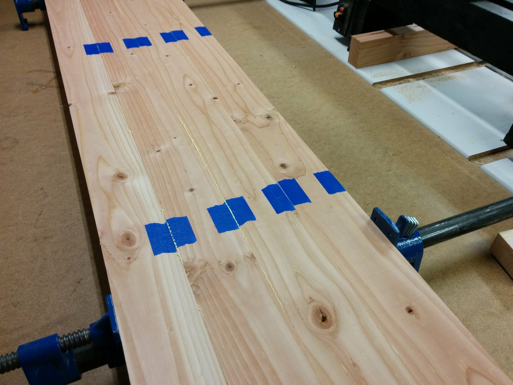
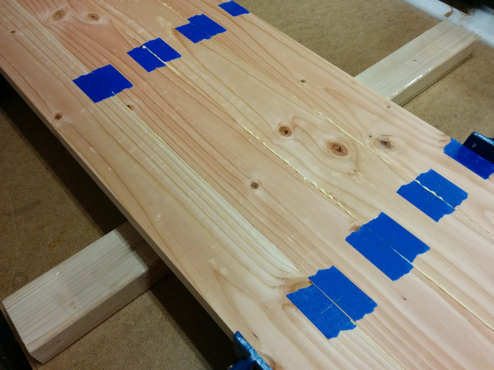
<< Back to Workbench: Part 4 – Gluing up the new top
<< Back to Workbench: Part 3 – Change of plans
<< Back to Workbench: Part 2 – Gluing up the top
<< 
Back to Workbench: Part 1 – Milling down some 2 x 4s

After letting it sit for 24 hours, the bench is now ready for the hardware.

Workbench: Part 6 – Finishing the benchtop

The workbench top is almost done. It’s been glued up and cut to size. Now all it needs is the finishing touches to get it ready for the hardware.

Adding a shallow rabbet on the ends of each piece.

The left and right edges of each section are going to have angle-iron that wraps around the corners. Since these will be recessed, I need to add a shallow rabbet on each edge. I did this with my table saw and a dado stack. The depth was pretty crucial but the width was approximate. I knew I wasn’t going to get a final fit until I rounded the corner so I just made sure not to make it too wide.

Cut a shallow rabbet on the left and right edges of the benchtop pieces.

I did a rough-fit just to make sure it was deep enough but not too wide.

This is how the angle-iron will sit on the edge.

A close-up view shows how I need to apply a roundover to the corner.

I need to add a roundover in the corner so the angle-iron sits flush.

I used a contour gauge to determine the radius of the inner corner.

Using a contour gauge to determine the correct roundover to apply.

The router bit that fit best is a 1/8″ roundover bit.

It looks like a 1/8" roundover bit will work.

I set the benchtop upside-down on my router table and used it to set the height of the bit.

Setting the height of the router bit.

Then it was a simple matter of pushing the piece along the bit. The piece was pretty big but since my router table is mounted on my table saw, it was actually not too bad.

Cutting the roundover on the left and right edges.

It looks like this is going to be a better fit. Now it’s time to finish the rabbet.

Now I need to take the rabbet back by a bit.

It looks like I need to take an additional 1/16″ off the top.

It looks like 1/16" will do.

I set the fence on my table saw so I would remove just a hair under 1/16″. I’d rather remove too little and have to take off just a bit more than remove too much.

Setting my fence so I can take ~1/16" off of the existing rabbet.

I carefully extended the rabbet just a bit. I didn’t end up needing to move the fence at all, but I did have to raise the blade up just a bit and make a second pass.

Running the pieces over the spinning dado stack.

That fits much better. It’s not perfect but it’s close enough.

That fits much better.

Applying a stain to the tops and sides.

Now it’s time to apply the stain. For this, I’m using Varathane Kona wood stain.

Time to apply the stain.

I applied a generous amount using a 3″ brush.

First I apply the stain with a 3" brush.

My wife followed up with a blue shop towel and dabbed up most of the stain before it could soak in too much. As you can see, this leaves a lot of the stain in the deeper spots, like the dents, mill-marks, and “worm-holes”.

The towel soaks up most of the stain but can't really get into the dents, mill-marks, or "worm-holes".

I’m pretty happy with how this looks so far.

Looks good so far.

We need to let it sit for about an hour before we do anything else to it.

Letting the stain sit for an hour.

We put the angle-iron on the rabbet to get an idea of how it’s going to look when we are finished. I think it looks pretty good.

This is how the angle-iron will look next to this stain.

After waiting an hour, we made sanding blocks out of scrap wood and 220-grit sticky-back sanding discs.

Making a sanding block out of a scrap piece of wood and some sticky-back 220-grit sanding discs.

We used these to go over the benchtops and knock back the high spots a bit.

Knocked back the high spots with the sanding block.

The contrast was a bit too much so my wife decided to lightly dab on some more stain in spots to bring the contrast under control.

Lightly dabbing on some more stain to reduce the contrast between the light and the dark parts.

It’s probably worth mentioning that we made sure to get the front and back of each piece.

Making sure we got the front and back of each piece.

Now we need to let it sit for a few more hours before we apply the polyurethane.

Letting it sit for another couple of hours.

Protecting it all with polyurethane.

For this project I’m using Varathane brand matte finish interior polyurethane. It goes on easily and rinses out with soap and water. An added bonus is that you don’t have to sand in between coats. I still prefer to sand right before applying the final coat.

For this project I am using Varathane brand matte finish interior polyurethane.

I used the same brush that I used for the stain to apply a generous first coat of polyurethane.

Applying the first coat of polyurethane.

After applying the first coat, I went over it lightly with the brush to smooth it out. You can see how the poly sits in the deeper spots. Our intention is to apply enough poly that it fills in these spots, making a smoother surface.

I'm hoping it will help fill up the low spots and even out the top.

Finished applying the first coat. I’m letting that sit overnight before applying the next coat.

Got to let it sit for a few hours before adding more coats.

I applied the second coat and let that sit for a few hours.

Applied the second coat.

Applied a third coat…and waited.

Third coat has been applied.

…and a fourth.

After the fourth coat has been applied, I'm starting to wonder how many more coats this is going to take.

I let the fourth coat sit for 24 hours. It looks like it’s ready to be sanded before applying the final coat. The polyurethane has helped smooth out the high and low spots a bit. I’m not going for a writing surface here so it doesn’t need to be perfectly flat.

The fourth coat is dry and ready for sanding.

I carefully flipped the pieces over so I can stain the underside. Obviously, this isn’t as critical as the top and I could probably not worry about it at all, but the smaller piece will most likely be attached the the main piece with a piano hinge and will hang down on the side when not in use. This means that the underside of the smaller piece will be visible at these times.

Turned the bench-top pieces over so I can stain the underside.

I started the tedious process of applying the stain to the underside. This piece is pine plywood and it soaks up the stain a lot faster than the oak. As a result, this is going to be much darker than the top.

Applying some stain to the underside.

I soaked up as much excess stain as I could.

Soaking up as much excess stain as I can.

After waiting about an hour and a half, I lightly sanded the underside with 220-grit sandpaper. I’m just trying to knock back any bumps before I seal them for all time under a layer of polyurethane.

I let the stain sit for about an hour and a half then I lightly sanded the undersides.

I applied a single coat of polyurethane to the undersides.

I applied a coat of polyurethane.

This is the only layer of poly that I am planning on applying to the underside. I’m going to let it sit for 24 hours before flipping the bench-top pieces back over and finishing the tops.

The polyurethane has been applied and needs to sit overnight.

After letting the poly coat on the underside sit for 24 hours, I flipped the benchtop back over and lightly sanded the top with 220-grit sandpaper in order to knock back any bumps or high points. This also further distressed the top.

I sanded the top with 220-grit to knock down some of the high spots.

I carefully applied the fifth and final coat of polyurethane and let it sit for twenty-four hours.

I carefully reapplied the fifth and final coat of polyurethane.

After sitting overnight, the finish on the bench-top is complete and now it’s time to attach the hardware.

After letting it sit for 24 hours, the bench is now ready for the hardware.

Do you have any tips on staining and protecting your work? What has worked for you? Let us know in the comments section below.  I’d love to hear from you. Also, please consider signing up for my mailing list to be notified of future articles. I am also available on social media. Stop by and say ‘Hi’. I can be reached at the links below.

Previous articles in this series…

Table Saw Enhancement – Converting Extension Table Into Router Table.

SawStop industrial cabinet saw with sliding crosscut table, extra wing, and router table.

This is a continuation of my other table saw enhancements, Attaching a Sliding Crosscut Table Without Cutting Down the Rails and Attaching an Extra Cast-Iron Extension Wing.

The additional cast iron wing that I attached to my table saw moved the wooden extension table another 10″ past the end of my rails. This allows me to relocate my router table to the far-right edge of the table saw without having to cut notches in my front and rear rails to accommodate the miter slot.

Converting the extension table into a router table.

I had to remove my fence in order to attach the additional cast iron wing. I didn’t want to put my fence back on yet but I realized that I needed to so I can cut a dado in the wooden extension table for the miter slot.  This is the same extension table that I had previously removed.  I temporarily reattached the front rail and did a quick fence alignment so my cut would be parallel with the edge of the table.  This led to a slight problem as you’ll soon see.

Temporarily reattached the front tube so I can use the fence to cut a dado in the extension table.

I wanted to make sure I didn’t accidentally cut through any screws so I removed the legs for the table.

I figured that I would make the miter track 6″ from the edge of the table.  This would ensure that I didn’t hit any screws while cutting the dado.  I wasn’t worried about hitting a screw and activating the brake in the SawStop since a screw by itself is too small to activate the safety system.  I mainly didn’t want to mess up the carbides on my dado stack.  I positioned the fence at the 6″ mark.

Positioning the fence.

I applied some blue painters tape to help prevent chipping and scratching the laminate on the edges of the dado.  In keeping with tradition, I miscalculated where I should put the tape.  You’ll see what I mean in a second.

Taping where I'll be cutting.
Taping where I’ll be cutting.

I clamped some scrap wood on the side of the table to help prevent tear-out.  I made sure the clamps were positioned where they wouldn’t get hit by the blades.

Clamping some scrap wood to help prevent tearout.

I lowered the dado stack so it would make a scoring cut first.  This is another step that can really help prevent the edge of the laminate from chipping.

Lowering the dado stack so it''ll just cut through the laminate.
Lowering the dado stack so it”ll just cut through the laminate.

I made my first pass.  As you can see, the blue tape wasn’t positioned correctly so my first cut didn’t have tape on each edge.  As it turns out this wasn’t a big deal.  The laminate that SawStop recently switched to for use on their extension tables is some high-quality stuff and didn’t tear out at all.  I didn’t have similar luck with the laminate for their older extension tables.

Didn't position the tape correctly but it didn't matter in the end.
Didn’t position the tape correctly but it didn’t matter in the end.

Here you’ll see one of the areas where I screwed up.  Remember when I said I did a “quick fence alignment”?  Well, I should have taken my time.  If I had, I would have noticed that in aligning my fence I also slightly loosened the clamping pressure of the fence on the front tube.  This caused my fence to slide a little bit as I was cutting and caused a slight unevenness in the dado.

Fence shifted while making this cut.

As you can see, the scrap wood kept the laminate from chipping on the edge.

No tear-out!
No tear-out!

I reattached the legs and temporarily clamped the extension table to the rails and the right wing, making sure it was flush. Then I drilled new holes through the sides of the wooden extension table for the bolts to attach it to the rails.

Lined up the table and drilled holes for the mounting bolts.

I then did the same thing on the back. After the holes were drilled, I reattached the table to the rails using the appropriate bolts, washers, and nuts.

Drilled the mounting holes on the back of the extension table.

I then reattached my outfeed table to the rear rail.

Reattached my outfeed table.

Now it’s time to mark the opening that I’ll be removing. I’m going to remove most of it with my jigsaw then clean up the rest with my trim router and a pattern bit.

Using the old router table as a template.

I laid the pattern on the tabletop in the spot where I am going to remove the material. Absolute precision is not critical at this point. I used a few pieces of painters tape to mark the inner edges of the opening.

Temporarily marking the inner edges of the template.

I then took the template off and ran some strips of painters tape over where the edges will be. The actual edges should be somewhat centered in the strips of tape.

Applied blue painters tape over the edges where I will cut out the insert opening.

Then I put the template back in place. Again, absolute precision isn’t critical at this point.

Set the template in place.

I used a red Sharpie to trace the opening on the blue painters tape.

Traced the outline of the opening with a red Sharpie.

I then removed the template yet again so I can see the outline I just traced.

Removed the template after tracing the outline.

I drilled 1/2″ holes near the inner corners.

The holes have been drilled.

I’m using a jigsaw to remove the bulk of the material, roughly cutting it out about 1/4″ inside the lines.

I'm going to rough-cut out the opening with a jigsaw.
I’m going to rough-cut out the opening with a jigsaw.

Nice and sloppy. The critical thing is not crossing over the line.

The piece has been removed.

I reapplied the painters tape since it got a bit chewed up then laid out the template. This time positioning is critical so I took my time. I got one end clamped down…

Carefully positioned the left edge of the template and clamped that side in place.

…then used a try square to make sure the template was square with the table.

Using a try square to ensure the template is square with the table.

Once I was satisfied that it was square, I clamped down the opposite end then applied one more clamp to each edge just for good measure.

Carefully clamped the other end in place and secured with additional clamps.

I outfitted my trim router with a 1/2″ pattern bit.

Positioning the router to cut out the opening.

It was throwing up quite a bit of dust so I set up a dust collection hood to grab most of it out of the air.

Getting pretty dusty so I set up my dust shroud.

I had a problem with the bearing on this pattern bit coming loose and the whole bit slipping. This caused a little gouge on the inner-right edge of the opening.

Chewed up the opening a bit when the bearing came loose. Otherwise, it looks okay.

I removed the template and the painters tape so I could inspect the edge. There was a little divot where the bearing came loose but other than that, it wasn’t bad.

Removed the painters tape. Other than the small goober on the right, it didn't turn out bad at all.
Removed the painters tape. Other than the small goober on the right, it didn’t turn out bad at all.

I used a file to break the edge a bit.

Broke the edges a bit with a file.

This particular extension table has some support bars underneath. They are only screwed in and are easy to remove.

The table braces are going to get in the way so I'm going to move them.
The table braces are going to get in the way so I’m going to move them.

I removed the support bars so I would have room for the Kreg PRS3040 Precision Router Table Insert Plate Levelers which installed easily from underneath the table.

Installed the Kreg PRS3040 Precision Router Table Insert Plate Levelers.

Each leveler has two set screws that are used for leveling the router insert.

The Kreg levelers went in easily.

I reinstalled the support bars. I had to move them by about 1/4″ from their usual spot.

I reattached the supports under the table.

The next step was to start hooking things up. I installed a 4-outlet electical box that was wired to a motor power switch.

I hooked up an electrical outlet and a knee switch under the table.

Then it was simply a matter of dropping the Rockler router lift in place and plugging in the router.

The router lift has been placed in the table and the router plugged into the outlet.

A little bit of leveling and I’m all done.

The router table is all finished.

I can use the table saw fence with the router table. This photo shows how close I can get it to the router bit. I will be making an auxiliary router table fence with built-in dust collection that I can attach to my table saw fence, but that’s a project for another day.

I can use the table saw fence with the router table as well.

That’s it! Up next is an enclosure for the router and maybe some drawers for storing router bits. For now, I’ve got some other projects that require my attention.

If any of this has been helpful to you, or if you have any suggestions or questions, please take a minute to post a comment below. I’d especially like to hear any suggestions for projects that you’d like to see me tackle.

Table Saw Enhancement – Attaching Extra Cast-Iron Extension Wing.

SawStop Industrial Cabinet Saw with an extra cast iron wing.


This is a continuation of Table Saw Enhancement – Attaching Sliding Crosscut Table Without Cutting Down the Rails.

Now that I’d removed my existing router table, I needed to relocate it to the right edge of my table saw. Since I use a miter slot on my router table and I wanted to avoid cutting notches in my front and rear fence rails, I decided to add an additional cast-iron extension wing to the right of my main saw table.

Installing an extra cast iron wing.

I had to remove the wooden extension table in order to attach the new cast-iron wing.  As a result, I needed access to the bolts in the rear rail so I took off my outfeed table.  This is giving me a good opportunity to clean some neglected areas of my saw as well.

Removed the outfeed table so I could access the rear bolts.

I then removed my wooden extension table.

Removed the wooden extension table.

I used some magnetic tool holders and attached them to the inside of the front and rear rails.  These will help hold up the cast iron extension wing while I get it bolted to the table.

Magnetic tool holders help to support the new cast-iron wing.

I temporarily attached the new wing to the existing wing using three bolts along with washers and lock nuts.  I was very careful to get the seam between the two cast iron wings nice and flush.  There wasn’t anything holding the new wing to the front and rear rails yet.  That was my next step.  I marked the holes in the new wing on the inside of the rails using a silver Sharpie.  Then I took this new wing back off.

Temporarily attaching the new wing to the existing wing.

I used a small drill bit (somewhere in the neighborhood of 1/8″ in diameter) to drill a starter hole.  You will want to take your time and use plenty of cutting oil when drilling through powder-coated steel.

Drilling the ~1/8" starter hole.
Drilling the ~1/8″ starter hole.

I then moved up to a step bit once the starter hole was drilled.  I believe I drilled this to be 3/8″ in diameter.  Again, take your time.

Expanding the hole with a step bit.

I added a countersink to the front of the hole once the hole was the correct diameter.  The bolts that are used for attaching the cast-iron wing to the rails are countersunk allen bolts.

Adding a countersink to the front of the hole.

This took a long time to do.  The steel on the SawStop rails is pretty tough stuff and I wanted to avoid having the powder-coating start to chip off.

Take your time with this so you don't chip the powder-coating.
Take your time with this so you don’t chip the powder-coating.

It took a while but finally the countersink was deep enough so the bolts didn’t stick out at all.  This is important so they don’t interfere with moving the fence back and forth.

Took a while but I'm done.
Took a while but I’m done.

I loosely  reattached the wing and started tightening up the bolts.  The holes in the cast iron wing are over-sized and not threaded so I had a little bit of wiggle room to help with alignment.

Loosely attaching the bolts.

I got the wing all tightened up and aligned properly.

Tightened and aligned.

The additional cast-iron has been nice to work on. Drilling through the powder-coating wasn’t as bad as I was expecting it to be. I’ll most likely add one or two more cast-iron wings in the future. I know that there is a limit to how much I can add before the saw starts to tip when I try to move it but the sliding crosscut table may help offset the weight of all the cast iron.

If this has been helpful or if you have any questions that I failed to answer, please leave a comment below.

Up next, I’m adding a router table to the right end of my table saw extension table.

Table Saw Enhancement – Attaching Sliding Crosscut Table Without Cutting Down the Rails.

SawStop Sliding Crosscut Table installed without having to cut down the front or rear rails.


My table saw is fairly decked out and I’ve made some modifications to it in the past but some of them weren’t working that well for me.

My saw is a SawStop Industrial Cabinet Saw 3 HP single-phase, 230 VAC machine (ICS31230) with a 52″ fence system and the sliding crosscut table.  As an experiment, I had previously taken the left cast-iron wing off and replaced it with a custom router table.  The reason behind having the router table in that spot is because I didn’t have any room on the far-right edge of the saw the way my shop was set up previously.  I needed to have it on the left but I wasn’t sure if it would work with the sliding crosscut table or if that would be in the way.

As it turns out, it wasn’t too awkward having the router table there. It did, however, affect the accuracy of the sliding crosscut table since it wasn’t supported by anything but a wooden table.

After I rearranged my shop I decided to move the router table to the far right edge of the table saw and reattach the sliding crosscut table to the left cast-iron wing as originally intended. In order to accommodate the router table miter slot without having to cut notches in the front and rear rails, I decided to add another cast-iron wing to my saw thereby pushing the extension table out another ten inches.

I also decided to use this opportunity to document how I attach the sliding crosscut table to the left cast-iron wing without having to cut my rails down. Since this is a fairly long post, I decided to break it up into individual posts. The links to the other modifications are at the end if this article.

Removing the router table and installing the Sliding Crosscut Table.

This is how my sliding crosscut table was attached previously. Notice that the cast-iron wing on the left of the main saw table has been removed and replaced with a wooden router table.

Time to undo this mess.

The sliding crosscut table mounted to a router table on the left of the saw.

I started by removing the router lift from my existing router table as well as the sliding crosscut table.  I also removed the front tube that the fence clamps to.

Removed the slider and the front tube.

Then I removed the old router table.  I’m using this as my routing template on my new table so I’m not getting rid of it just yet.

Removed the old router table.

I reattached the cast iron wing.  The problem with adding a sliding crosscut table to a table saw is that you will typically have to cut your rails and tube down since they will usually stick out past the cast iron.  

I got some 3/4″ thick HDPE and cut it to the dimensions for the side of my saw, which is 1-1/2″ thick and 30″ deep.  After cutting this down I drilled holes to match the side of the table.

HDPE spacer for attaching the sliding crosscut table to the left wing.

Once it’s drilled, you can hold it in place on the side of the cast iron wing and attach the sliding crosscut table to it.

Holding the spacer in place.

You’ll most likely need to get longer bolts for this.  With the SawStop sliding crosscut table, the bolt type and size isn’t too critical.  You just need to make sure they don’t interfere with the sliding mechanism.

Loosely fitting the sliding crosscut table and the HDPE spacer to the left cast-iron wing.

Get it all tightened up and flush and you are good to go.  I recommend using a pretty dense material for this spacer.  You could probably use some sort of hardwood but you really want to be particular with how you cut it since any discrepancies can cause your table to be out of alignment.

Tighten it up and you're done
Tighten it up and you’re done

This is the first of three table saw enhancements that I implemented this time. Check out the next two below. Did this help you? Do you have any suggestions or a completely different way of attaching a sliding crosscut table to your saw? If so, please leave a comment.

All done with two slabs cut to 5' and 2' in length.

Workbench: Part 5 – Cutting the benchtop to size

The top is all glued up so now I need to strengthen it by attaching 1/2″ plywood to the underside. I can then cut it down to the final size to prepare it for finishing.

Looking at the underside of the glued up benchtop.

There were a few spots of glue squeeze-out that I decided to remove so they don’t interfere with attaching the benchtop to the plywood. I just scraped them flat with a chisel.

Removing the glue squeeze-out with a chisel.

I am attaching two sheets of 1/2″ plywood cut to 2′ X 4′ pieces. I laid them out to see which would be the best placement for them. The benchtop so far is about 25″ deep so there will be a lip overhanging the plywood at both the front and back. My initial plan was to cut the front and back edges flat then attach a border, but that plan changed, as you’ll see in a moment.

Laying out the 1/2" plywood.
Laying out the 1/2″ plywood.

I am using Loctite PL 510 construction adhesive to attach the plywood to the benchtop.

LocTite PL 510 construction adhesive for attaching the plywood.

I ran a bead of the construction adhesive down the length of each strip of flooring. This is, of course, working on the underside of the benchtop. Then I placed the plywood sheets on top of that. I tried to get it relatively centered.

Attaching the plywood with the construction adhesive.

I clamped and cauled the plywood sheets to the benchtop and let it dry for 24 hours.

Clamping the edges.
Clamping the edges.

My original plan was to mill down some more of the flooring scraps and make a border along the front and back of the benchtop that was 1-1/4″ tall and 1/2″ deep. This was mostly to cover the plywood that is being attached to the underside of the benchtop. I started by cutting the tongue off the side of the flooring pieces.

Cutting the tongue off several pieces of flooring.

After that I cut off the groove on the opposite side.

Removing the groove from several pieces of flooring.

Then I trimmed the tongues and grooves off each of the ends.

Using the miter gauge to remove the tongues and grooves from the ends.

Finally I trimmed off the grooves along the bottom of the flooring pieces. I also ended up shaving a bit off the tops just to clean them up.

Cutting the grooves off the bottoms of the flooring pieces.

This left me with some nice oak stock to use for the front and rear trim.

Now this gives me some nice usable stock to work with.

The final width of each piece was a little over 1-7/8″ wide…

This leaves me with ~1-7/8" of material to work with.
This leaves me with ~1-7/8″ of material to work with.

…and 5/8″ thick.

This gives me some nice 5/8" stock.
This gives me some nice 5/8″ stock.

I removed the clamps and cauls and decided to get my wife’s opinion on the front and rear trim idea. I’m glad I did. She had the idea of just cutting the milled stock into strips and gluing them to the lip, therefore just covering the plywood and not the edges of the oak flooring.

The lip runs the whole length of the benchtop on both the front and back.

I cut some of the milled oak stock down to usuable pieces. I decided to just make them 5/8″ X 5/8″.

Cutting the oak stock into 5/8" X 5/8" strips.
Cutting the oak stock into 5/8″ X 5/8″ strips.

I was able to get enough strips by cutting down just 4 of the milled oak pieces. This leaves me with some more milled oak stock to use for other projects.

All the strips cut.
All the strips cut.

I laid out the pieces and applied a bead of Titebond 2 to the lip.

Applied a bead of Titebond 2 to the lip on the underside of the workbench.

I attached the oak strips and clamped them in place with small quick-release clamps.

Holding the strip in place with some small clamps.

The strips wanted to pull away from the plywood in a few spots so I used some larger clamps to apply lateral pressure. I don’t have a lot of clamps that are over 24″ so I had to get creative with some of them, but it all worked fine in the end.

Getting creative with some clamps that are just a bit too short.

After the glue dried I did the same thing for the back of the bench.

Applying some lateral pressure with some larger clamps.

There was some glue squeeze-out on the underside of the benchtop.

Got some glue squeeze-out to clean up.

I used a random orbital sander on the entire surface of the underside and…

Sanding the bottom smooth to get rid of the glue squeeze-out.

…it looks a lot better now.

Edges look good from the underside.

Now it was time to cut everything down to size. I took the glued up benchtop to my SawStop table saw so I could trim off one end.

Trimming off the edges of the benchtop at the SawStop table saw using my sliding crosscut table.

The ends of the workbench will be covered in metal. I’ll get to that in a future article. All I need now is for them to be flat.

Edge is nice and flush now.

I then trimmed off the opposite end.

Trimming off the opposite edge at the table saw.

It looks so much better now that I have trimmed off the excess on the ends.

Both edges are nice and flush.

I then trimmed the excess material off the front and the back.

Trimming the front edge at the table saw.

This was the look I was going for.

The front is nice and flush now.

The benchtop was pretty unwieldy since it was so huge. As a result, the table saw left some burning on the edges.

The table saw caused a little burning on the edges.

The random orbital sander easily removed the burn marks.

The burning is easily removed with a random orbital sander.

The plan was to turn this into a 5′ long workbench with a 2′ long flip-down wing. I marked the benchtop at 5′.

Marking the benchtop at 5'.
Marking the benchtop at 5′.

I used my SawStop sliding crosscut table to cut the workbench at the 5′ mark.

Cutting the benchtop to length using the SawStop sliding crosscut table.

The sliding crosscut table makes it very easy to perform this type of cut.

Cutting it down at 5'.
Cutting it down at 5′.

It cut cleanly and didn’t really burn it except for where I stopped pushing the material so I could take the picture above. A little sanding and it disappeared.

Finishing the cut.
Finishing the cut.

The workbench is now cut to the final size and is ready to be finished.

All done with two slabs cut to 5' and 2' in length.
All done with two slabs cut to 5′ and 2′ in length.

If you have any questions or comments, please leave them below.  I’d love to hear from you.

Workbench: Part 4 – Gluing up the new top

This is a continuation of Workbench: Part 3 – Change of plans.

Time to glue it all up.

My worbbench/outfeed/assembly table has a torsion box top so it makes a good surface for gluing something like this up.  I have a 1/8″ thick piece of hardboard that serves as a sacrificial top but I would still prefer to avoid gluing the pieces to that if at all possible.  To help with this, I taped down a layer of wax paper to the benchtop.

Then I laid out the pieces how they will be glued together.

I decided to do a little distressing before the glue-up.  This could have waited till after but I was anxious to try out a technique I picked up.  I made what I call a Smackem Stick.  It is just a piece of wood with a handful of screws sticking through it.  I used a cut off from another project.  Ignore the groove running the length of the side.  After I made this, I proceeded to beat the hell out of the boards.  After the stain is applied, these should hopefully look like worm holes.  since this is oak that I’m working with, these screws didn’t go too deep.

I wanted to try out the stain so I grabbed one of the sample boards that I did some experimenting on earlier and applied some Kona stain.  I will go over this stain technique later when I do the entire table top.

I separated the first two rows to get them ready to glue together.

I used a spring clamp to stand the pieces with their grooves facing up.

I then ran a line of Titebond 2 in the groove.

I laid out the first row.  I was careful to make the seams on the side of the boards that are facing the second row nice and flat.

I then attached the second row and clamped it together to dry.  When I inserted each piece, I put a line of glue in the small groove in the right side, then I inserted the following piece into that, being sure to put glue in it’s groove as well, and so on until the last piece which I didn’t do this to since it’s the last piece in the row.

After letting the first two rows dry for at least an hour, I took the clamps off and put on the third row in the same way.

After the third row dried, I realized that it would be easier to clamp these if I cut off the tongue on the front row since I won’t be using that anyway.

This made for a nice flat surface to clamp to.  I should have done this before gluing any of this together but it doesn’t hurt anything to have waited til now.

Then I clamped the fourth row on…

…and the fifth.

Once I got to the sixth row, my quick-release clamps would no longer reach so I switched to my bar and pipe clamps.

I attached the seventh row…

… and the eighth…

… and the ninth…

…and the tenth.

For the eleventh and final row I needed to get creative with my bar clamps since they aren’t quite long enough to reach.

In the end, it glued up okay.  The pieces have some gaps in them on some of the edges.  This is why they weren’t used on the floors, but for a project like this they add character.

The next step is cutting it down to a workable piece.  We’re still planning out the legs and possible drawers.  Also, I noticed that this piece has a slight bow to it from front to back.  I’m not surprised at this, but it means that I may have to attack a backer board to the underside and make some sort of border to hide it.  That should be in the next article.

If you have any questions or comments, please leave them below.  I’d love to hear from you.

Back to Workbench: Part 3 – Change of plans.

Back to Workbench: Part 2 – Gluing up the top.

Back to Workbench Part 1 – Milling down some 2 x 4s.

Workbench: Part 3 – Change of plans


This is a continuation of Workbench: Part 2 – Gluing up the top.

After gluing up half of the top, I repeated the process and got the other half glued up as well.

Both halves, ready to be glued together.


Once it was dry I joined them together with glue and biscuits just like I did for the individual boards.

Glue and biscuits applied to one half.

Pressing both halves together.

Both halves clamped and cauled.


After taking the clamps and cauls off I was left with a fairly warped but completely glued up benchtop.

Clamps and cauls removed.


At this point, the project wasn’t looking too promising.  My goal was not only to make a benchtop but to see if it can be reasonably accomplished using common 2 X 4 material.  Unfortunately, they are so dimensionally unstable that they do a lot of twisting and warping as they dry.  Maybe if I had these sitting in my shop for a few seasons so they can thoroughly dry then the end result would have been better.  Still, I was somewhat determined to make this work.


I started sanding it using a random orbital sander.

Started with a random orbital sander.


This was taking a long time so I switched to a belt sander.  This want a lot faster but I was still unhappy with the results since there was so much warpage to this.  I know I can eventually get it to work but I’ll have to remove so much material that  it won’t be as sturdy as I want it.

Switched to a belt sander.


It was at this time that my wife asked if I had any of the leftover wood from our newly installed hard-wood floors.  She had the idea that I can just use that since it already has the tongue-and-groove in place, plus she likes the look of oak more than fir.  Normally, I’m not a fan of oak but I had to agree that this would look better and be stronger even though the tabletop would be 3/4″ rather than 1″.

I decided to give it a shot.  I gathered up the scrap wood flooring and started laying it out.  I needed to get enough material to make a 7′ X 2′ section.  The plan is to have a 5′ wide bench with a 2′ wide flip up extension.

New plan! Laying out the oak flooring.


I had to cut some mating grooves in a few of the pieces but I was able to get enough material.  Once it was laid out, I attached a piece of blue painters tape to each piece so I could label them.

Painters tape applied for labeling.


I labelled each piece with the row (number) and which order it is in from left to right (letter)

Each piece labeled.
Each piece labeled.


Now, this is where this gets interesting.  One of the reasons my wife wanted me to use the oak flooring is because she wanted me to try to get “mill marks” on some of the boards.  Normally, I’m not a fan of faux-finishes and antiquing techniques, but this was an interesting challenge.

I tried approximating it by hand with 24 grit sanding pads and the result wasn’t pretty (as I expected).  The other technique I wanted to try was to put actual milling marks on the wood.

To accomplish this, I needed to get a blade that I could damage.  Specifically, I needed a 10″ table saw blade without carbides.  I knew I wasn’t going to find this in the store so I would have to look for a used blade.  I started my search at Habit for Humanity ReStore.  I couldn’t find anything there that was 10″ so I decided to try at a pawn shop.  I eventually found an old Craftsman blade that had all of my requirements and was new in the box.  To top it all off, after I told them why I was getting it, they knocked $6.00 of the price.

Found a cheap 10" blade with no carbides.
Found a cheap 10″ blade with no carbides.

As you can see, it's cheap but in decent shape.
As you can see, it’s cheap but in decent shape.


To add the mill marks I took one of the teeth and bent it towards what would be the right of the blade after it was installed on the saw.

Bending one of the teeth with a pair of vice grips.


Then I installed it on my saw and made a few test cuts.  I then bent it a few more times until I found the right amount.

The blade installed. The bent tooth is marked with an arrow.


Here’s a test cut.  I’m going to do a bit more distressing and see the final result after I stain this wood.

Sample mill-marks.
Sample mill-marks.


Feel free to leave a comment below and let me know if you’ve tried this technique or have any other ways of distressing wood that have worked for you.
Up next: Workbench: Part 4 – Gluing up the new top.


Back to Workbench: Part 2 – Gluing up the top.

Back to Workbench Part 1 – Milling down some 2 x 4s.


Workbench: Part 2 – Gluing up the top

This is a continuation of Workbench Part 1 – Milling down some 2 x 4s.

We got another snow day so this gave me an opportunity to work some more on my wife’s workbench.

Now that the boards have all been milled down, it’s time to start gluing them together.


For this project, I knew I was going to need a few sets of cauls.  If you are unfamiliar with a clamping caul, read on…

A clamping caul is simply a set of boards that are used to keep the top and bottom of a wide glue-up relatively flat.  Their use will make sense at the end of this article.  They are extremely easy to make.  I made two sets for this glue up.  I started with some 1 X 3 stock that I cut down to be a few inches longer than the width of the final glue up.

Cutting down the 2 X 3.

The benchtop I am making is going to be 24″ deep so I made my cauls about 28″ long.  There’s no need to be exact, just make it a bit longer than the final glue up.

The boards have been cut to 28" long.
The boards have been cut to 28″ long.

After cutting four pieces that are 28″ long, I took them to my oscillating belt sander.  This step is optional but I find it really helps.  What you want to do is add a little bit of a slope at both ends of one side of each caul.

Sanding a slope at the ends.

The end goal is a set of boards that have a gap between them at the ends.  This is so when you attach them, the clamps will pull them together but it won’t bow up in the middle.

The gaps at the ends of the cauls.

After I shaped them with the sander, I covered them in packing tape so the glue won’t stick to them.

Packing tape applied to the cauls.

Now, time to work on the actual benchtop.  First I laid the milled boards out how they will be glued together.

Arranging the boards.

I am going to be using biscuits to align everything so I put little pieces of painters tape on the edges of the boards where I was planning on putting the biscuits.

Tape applied to the boards.

Afterward, I made marks where I should center the slot for the biscuits.  The placement here isn’t critical.

The biscuit slot alignment marks.

Biscuit slot alignment marks.

Next I added some tape so I could number each board.  The reason I’m doing this with tape rather than just writing directly on the boards is because these boards are douglas fir and are pretty soft.  I didn’t want to make indentations from a pencil on them if I could avoid it.

The boards are all numbered and in order

Using the marks I had drawn, I used my biscuit joiner to make slots at all of the marks.

Lining up the biscuit joiner to cut the slot on the mark.

One of the biscuit slots.

Biscuit slots cut into one of the edges.

Now it’s time to try gluing this all together.  I decided to do this in sections, gluing up half at a time.  Setting up a few pipe clamps, I arranged the boards up so I could glue up four of the eight boards.

The boards are arranged so that the glue can be applied.

I applied a liberal amount of glue to the edges of three of the boards, including some extra glue in the biscuit slots.  Then I inserted a size 10 biscuit in each slot on the three boards with glue applied.

The biscuits are in place after the glue was applied to three of the edges.

Then I carefully rotated the second, third, and fourth board and inserted some glue in those biscuit slots.  After that, I laid the boards out on the clamps so the biscuits inserted into the slots on the adjacent board and started to bring the clamps together.  I didn’t really tighten them that much since I needed to nudge a few of the boards with a rubber mallet to get the marks on the tape to line up again.


I got them all aligned and started to tighten up the clamps.

The glued up pieces being aligned to the marks on the tape.

Now it’s time to attach the cauls.  I started by sliding one of the cauls under the glued up boards.  The side of the caul that I sanded the slope onto is facing up.

The bottom part of the caul set in place.

Then I set another caul on top of the glue up with the sloped edge facing down.

Setting the top of the caul in place.

Then I clamped them together.  The slopes on the edges allows the cauls to bend as they “give” a little bit but will direct most of that deformity to the edges of the cauls instead of raising up off the glue up in the middle.

Both parts of the caul clamped together.

I attached the second set of cauls at the other end along with a few more clamps.

The second caul attached near the other end.


Time to wait…

After this sets up, I’ll do the same to the other half.  That’s going to have to wait until another day.


Up next: Workbench Part 3 – Change of plans.


Back to Workbench Part 1 – Milling down some 2 x 4s.