Studio Desk – Part 3: Assembling the Racks

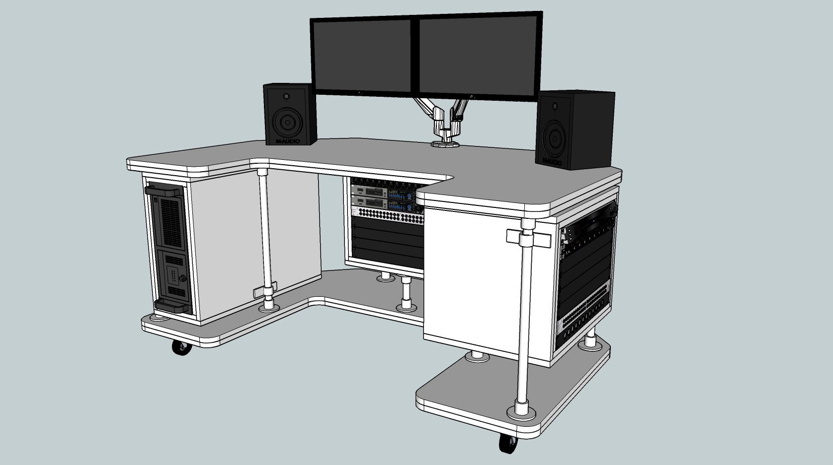
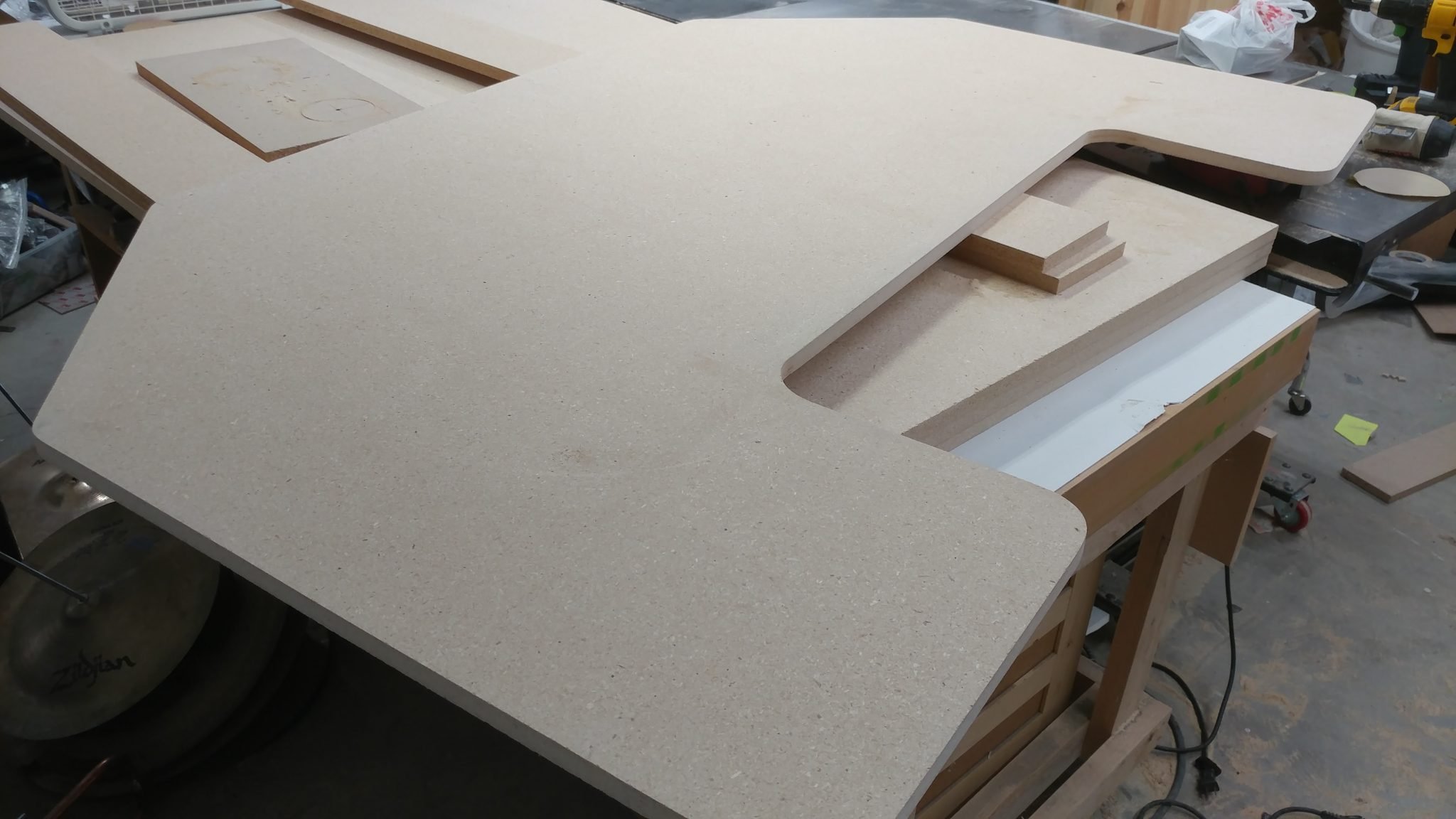
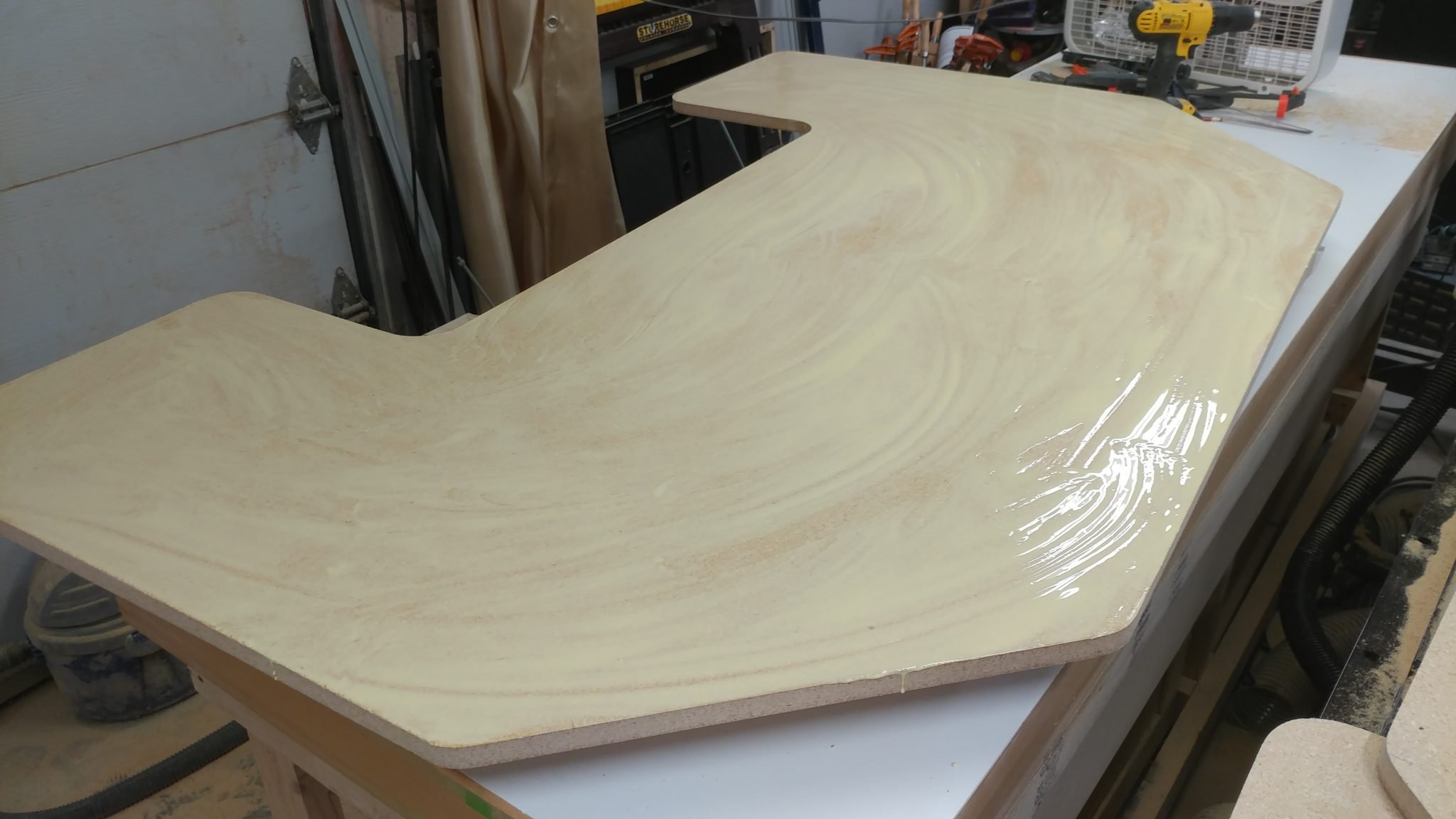
The top and bottom are ready to be stained and finished.  I’m going a bit out of order at this point.  I have already finished the top and the underside of the bottom but I’m going to bundle that in with my next post.  Here, I’m going to show how I assembled the carcases for the racks.

If you look closely, you will notice the stained desk bottom in the background of some of these photos.


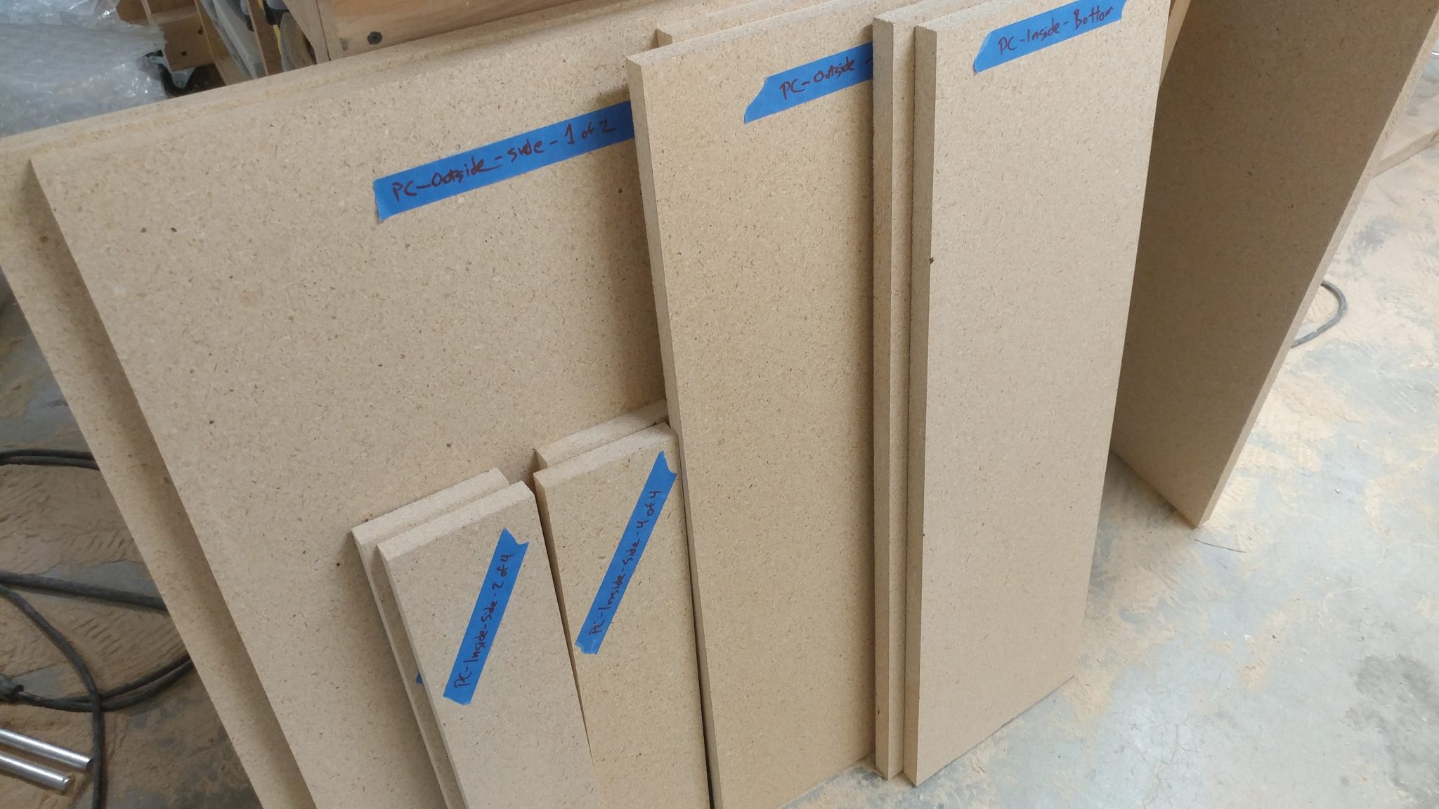
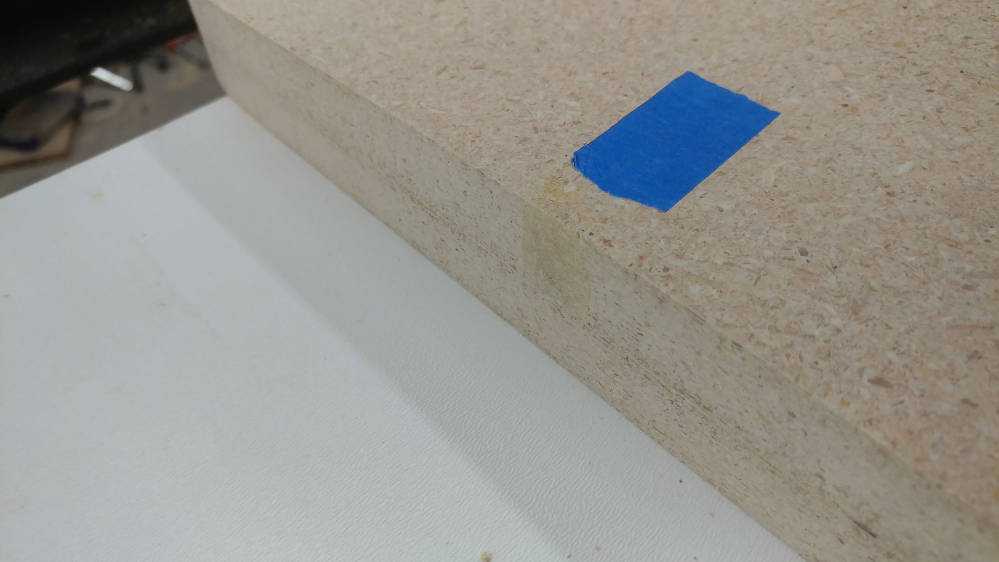
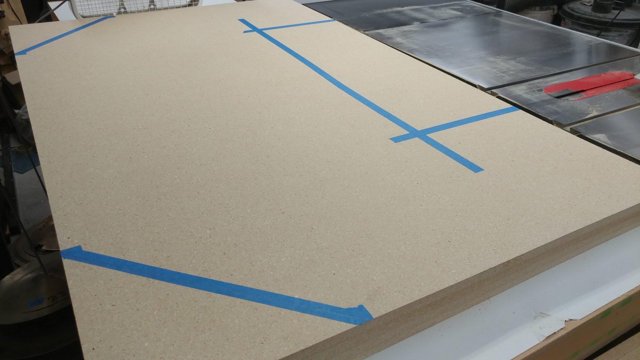
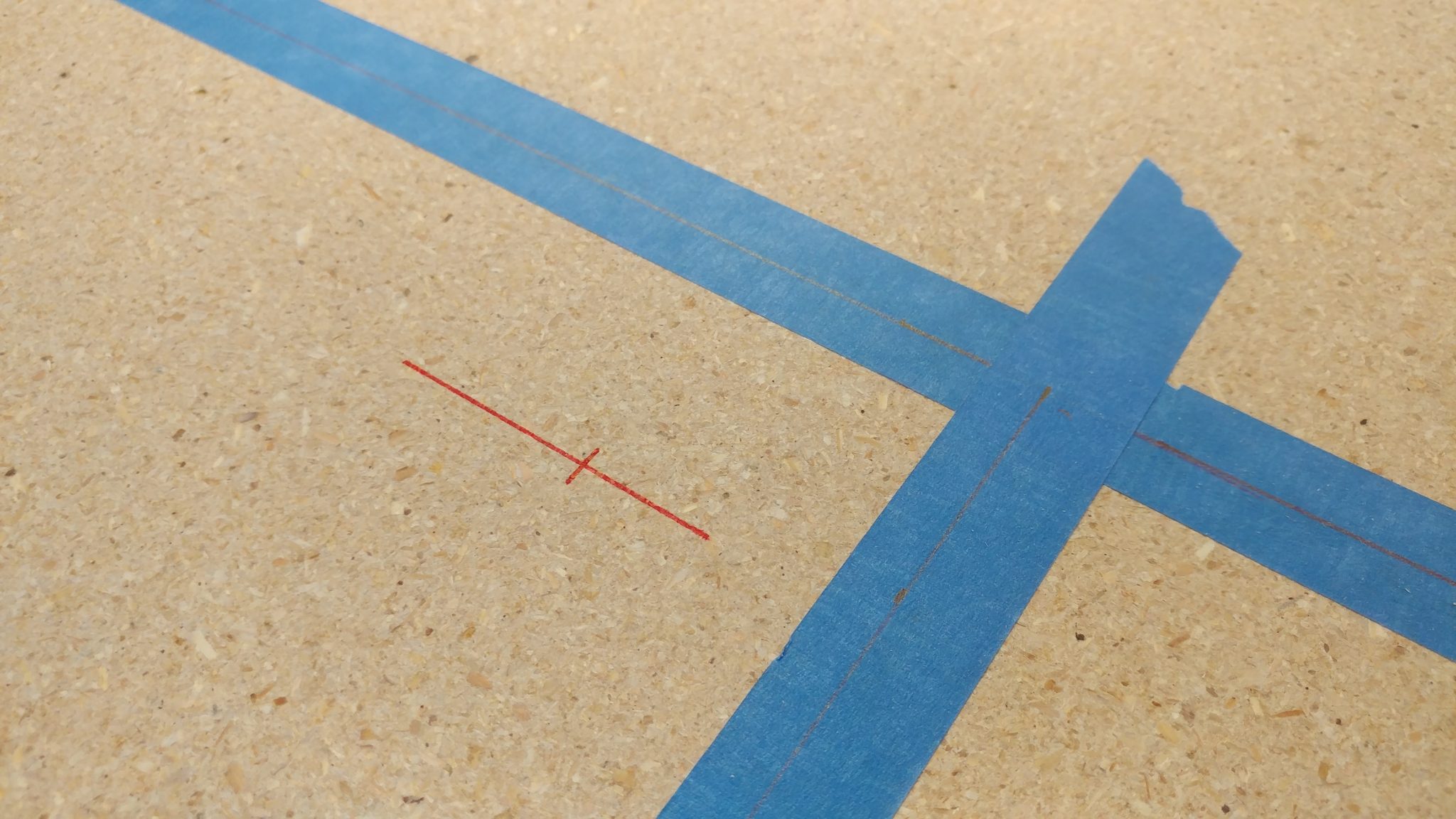
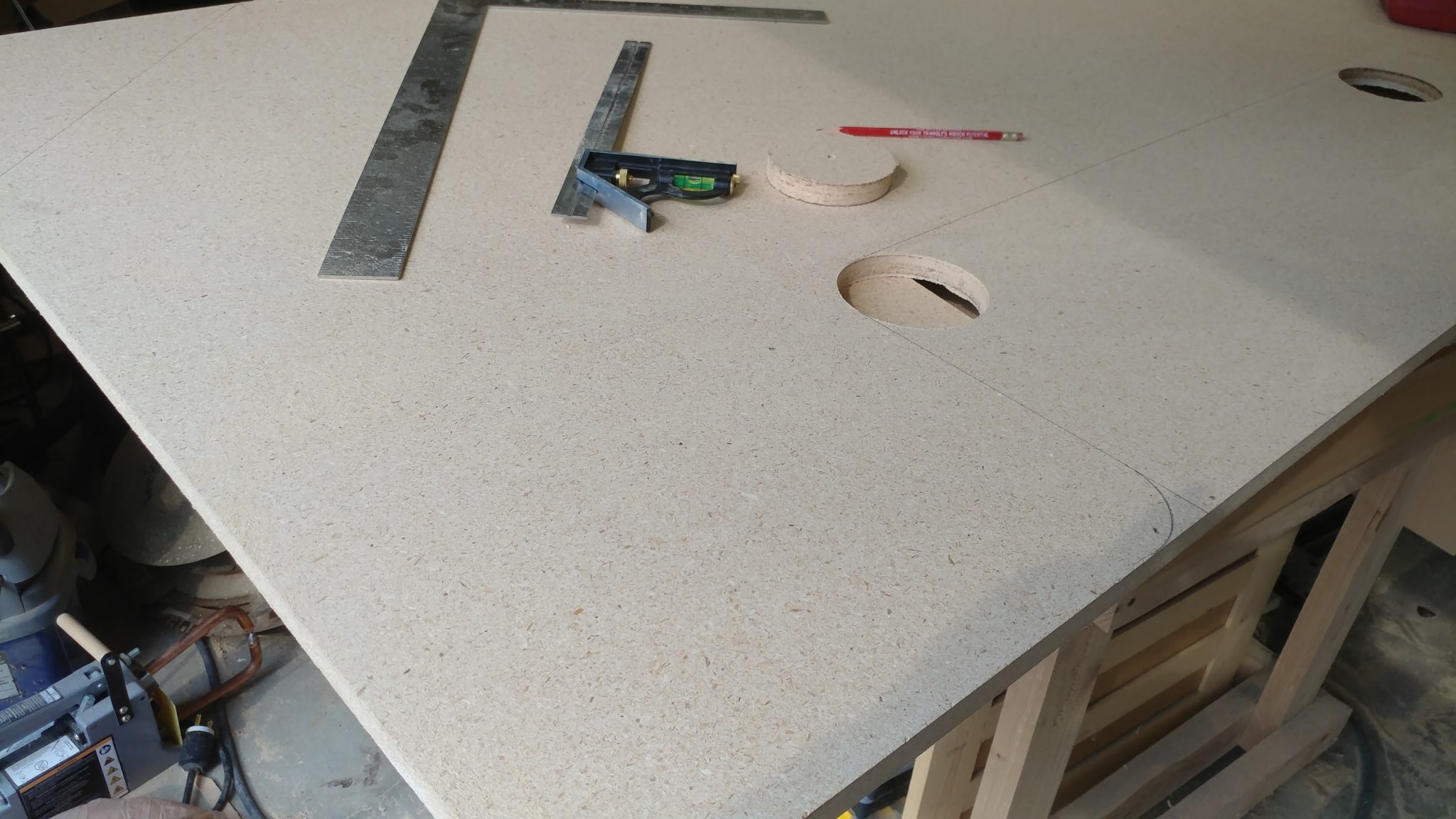
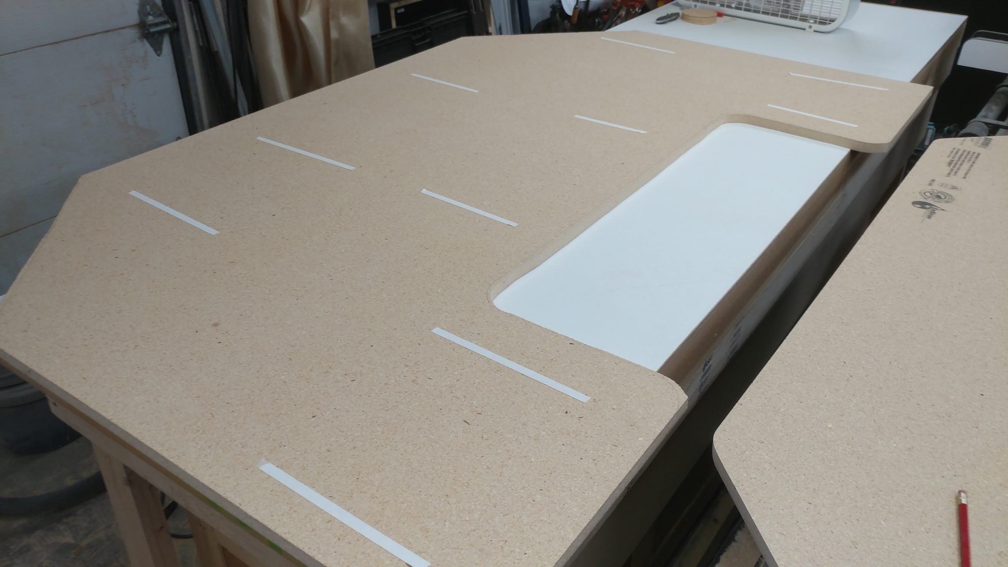
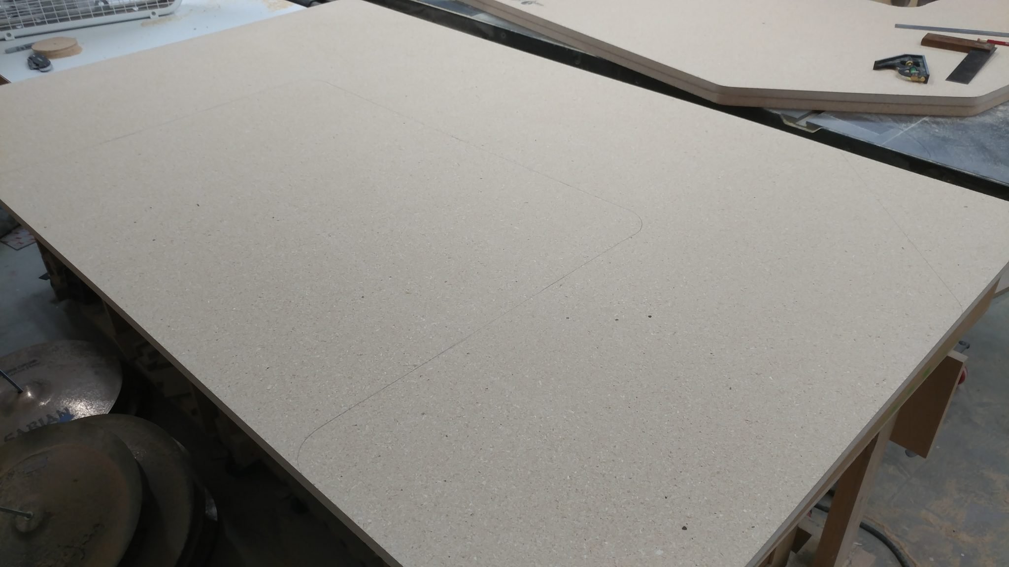
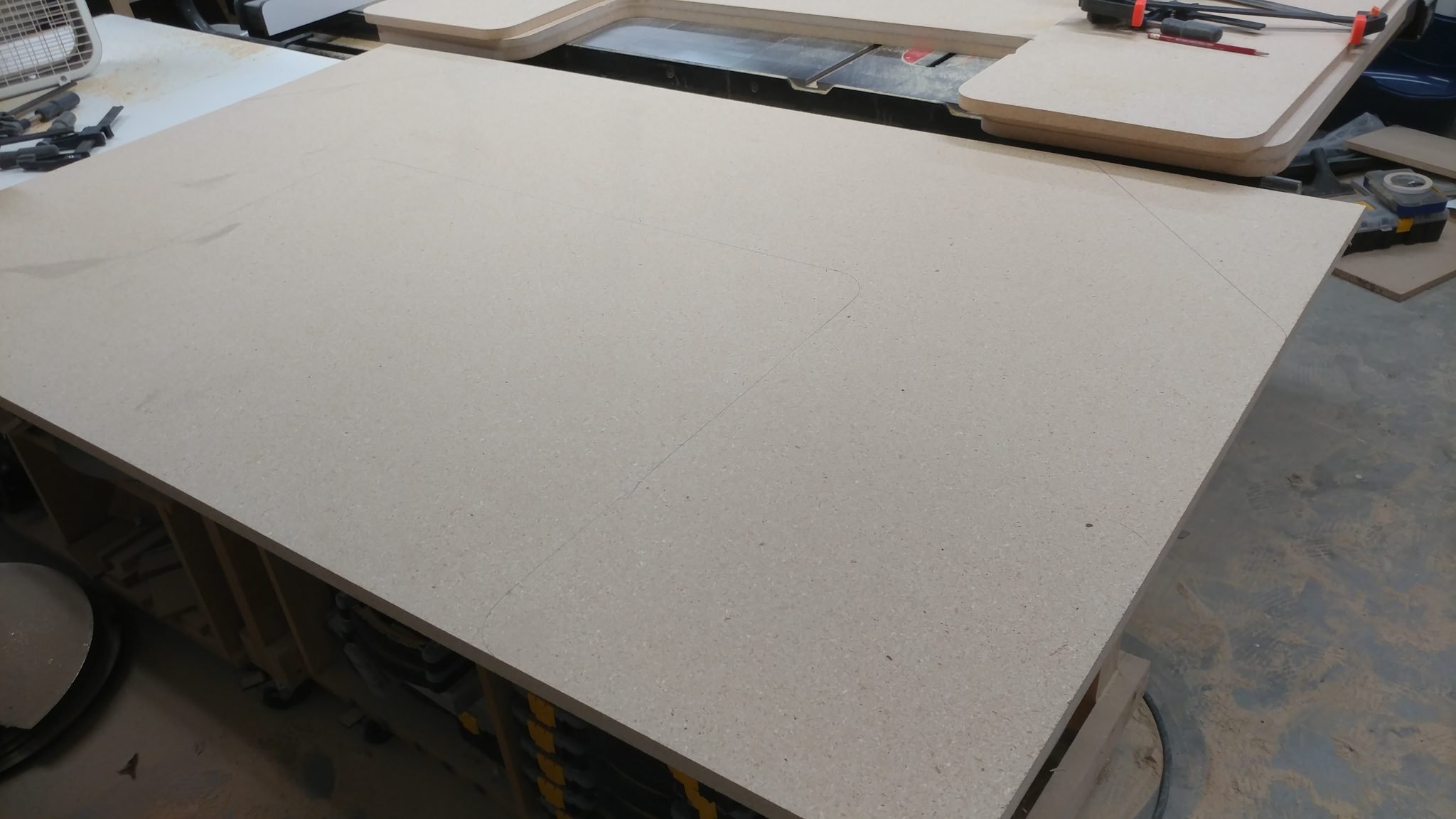
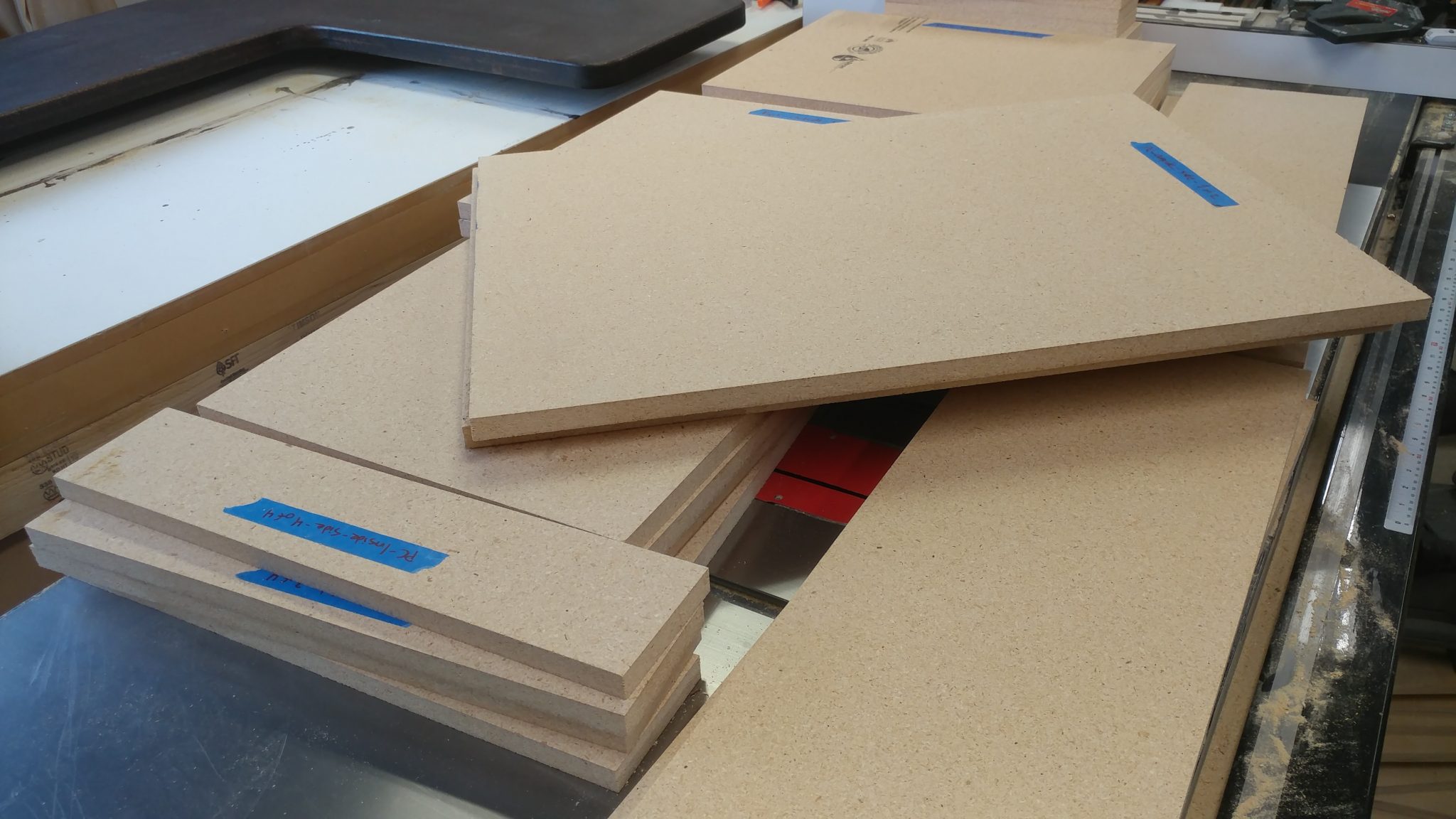
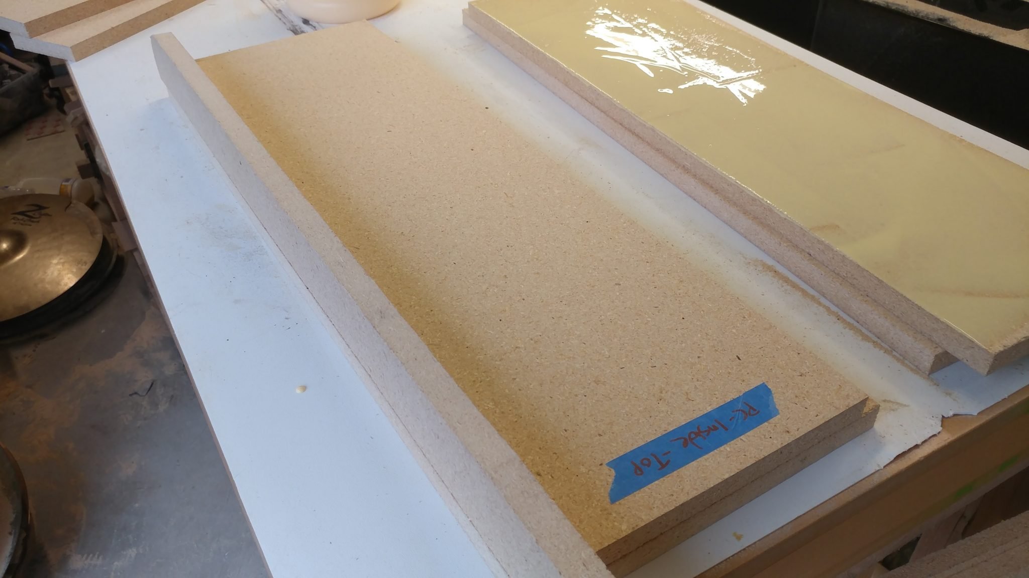
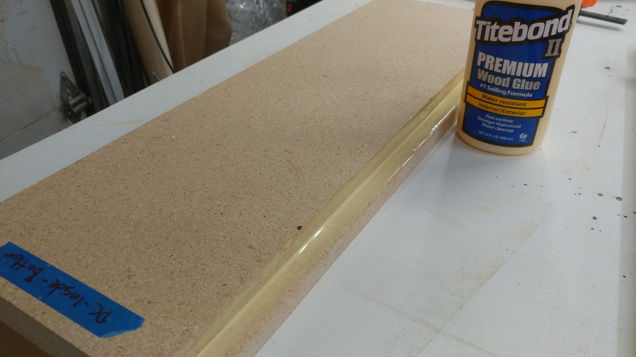
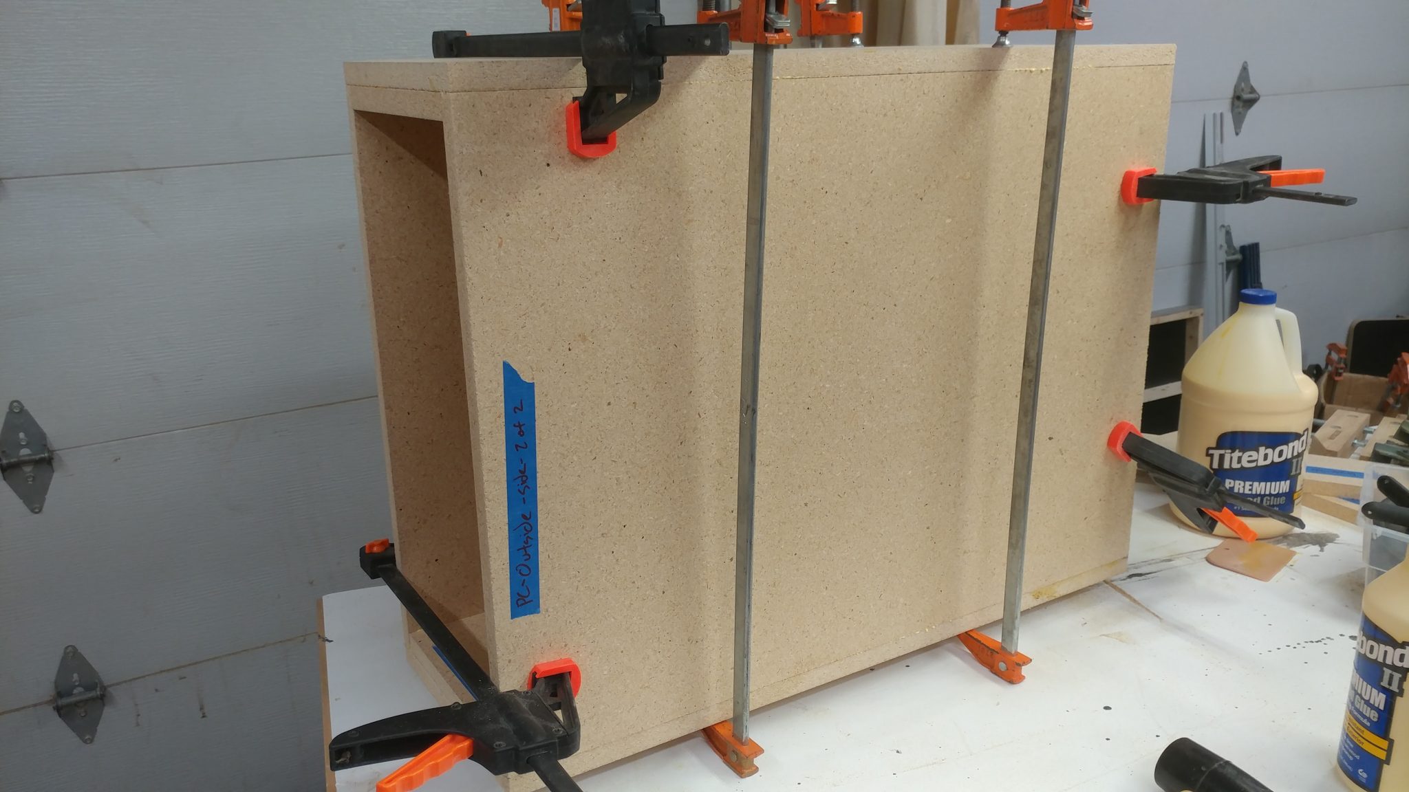
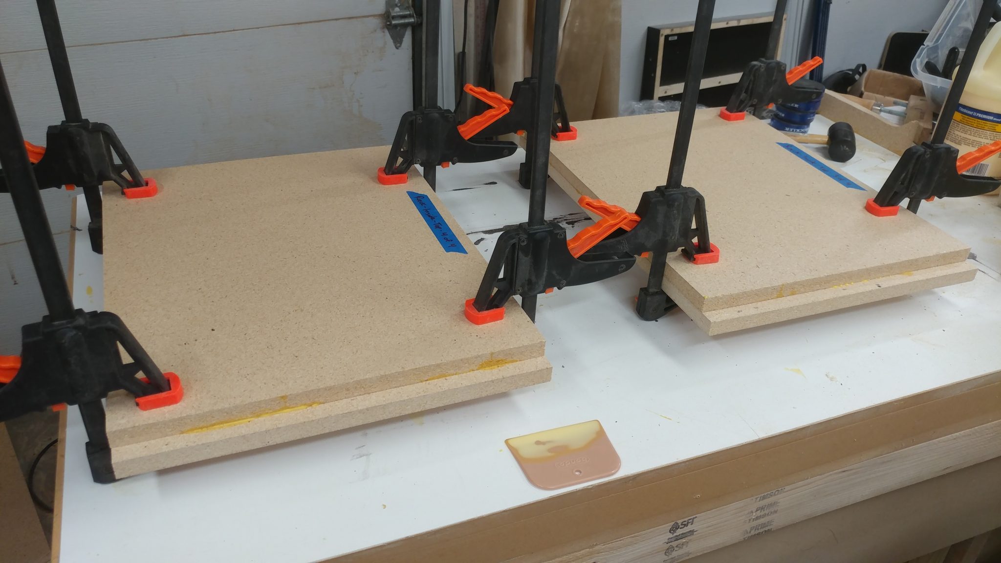
I started with the boards all cut.  I’m not going to show you how I did this since it’s just a bunch of cutting at the table saw and is quite boring.  For something like this, I think it’s really important to clearly label the pieces.  I did this with blue painters tape and a Sharpie.


Assembling the PC Case

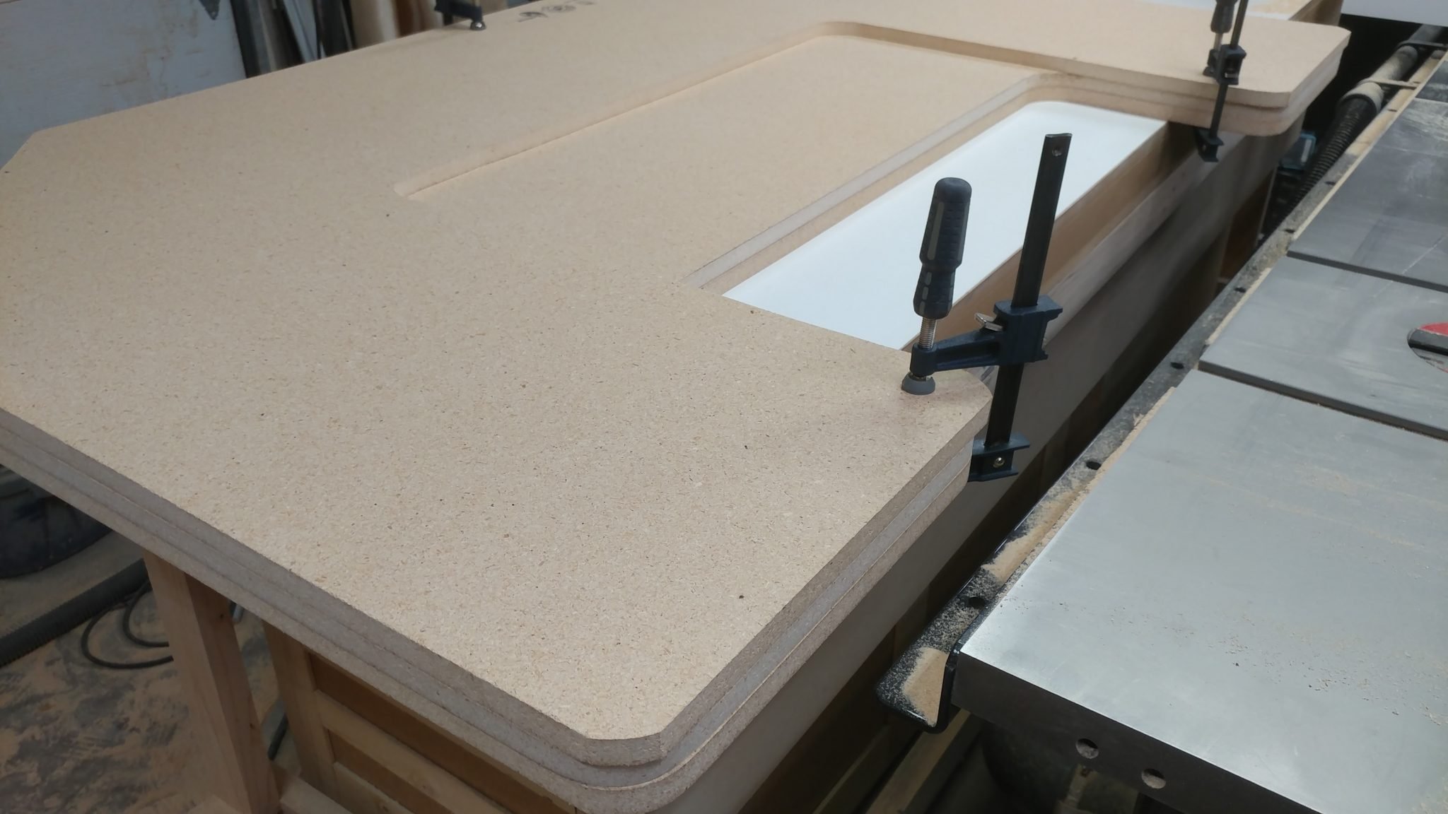
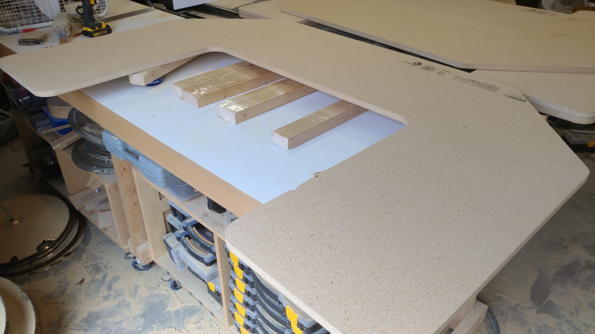
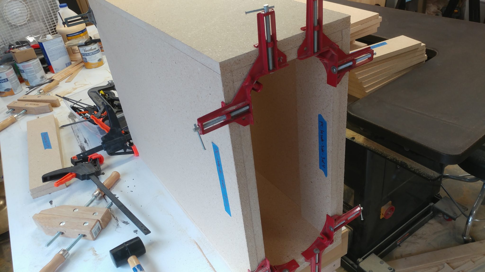
Before doing any glue-up I like to do a dry fit just to make sure I haven’t screwed anything up.  I did this with some corner clamps and a quick-release clamp.  Everything looks good.


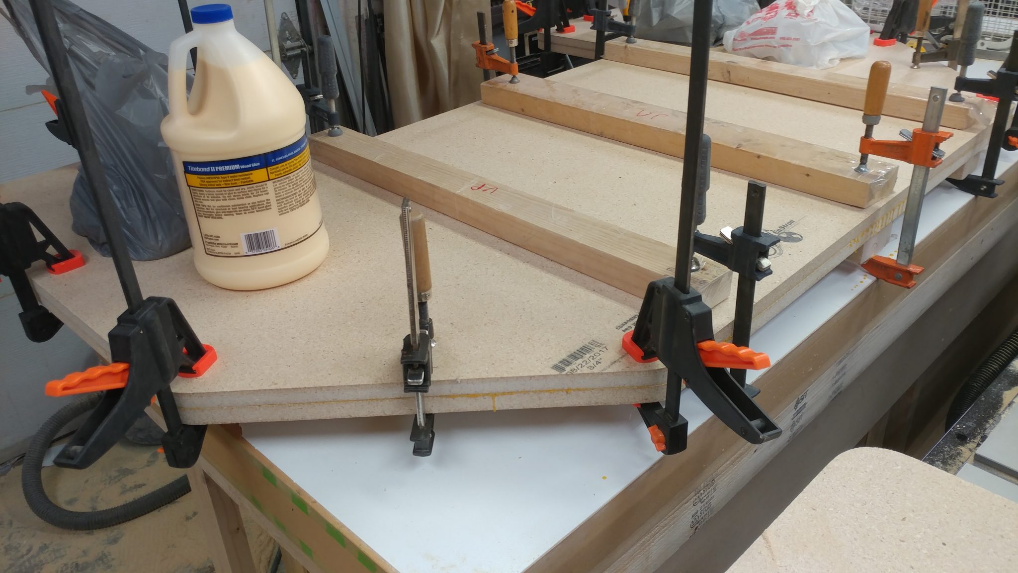
I decided not to have any visible fasteners on the wooden parts of the desk so I’m holding the whole thing together with a butt-load of Titebond II wood glue.  Here, I am attaching the inside of the tops and bottoms to the outside of the tops and bottoms of the PC case.  I spread a good amount of wood glue on the underside of the insides…


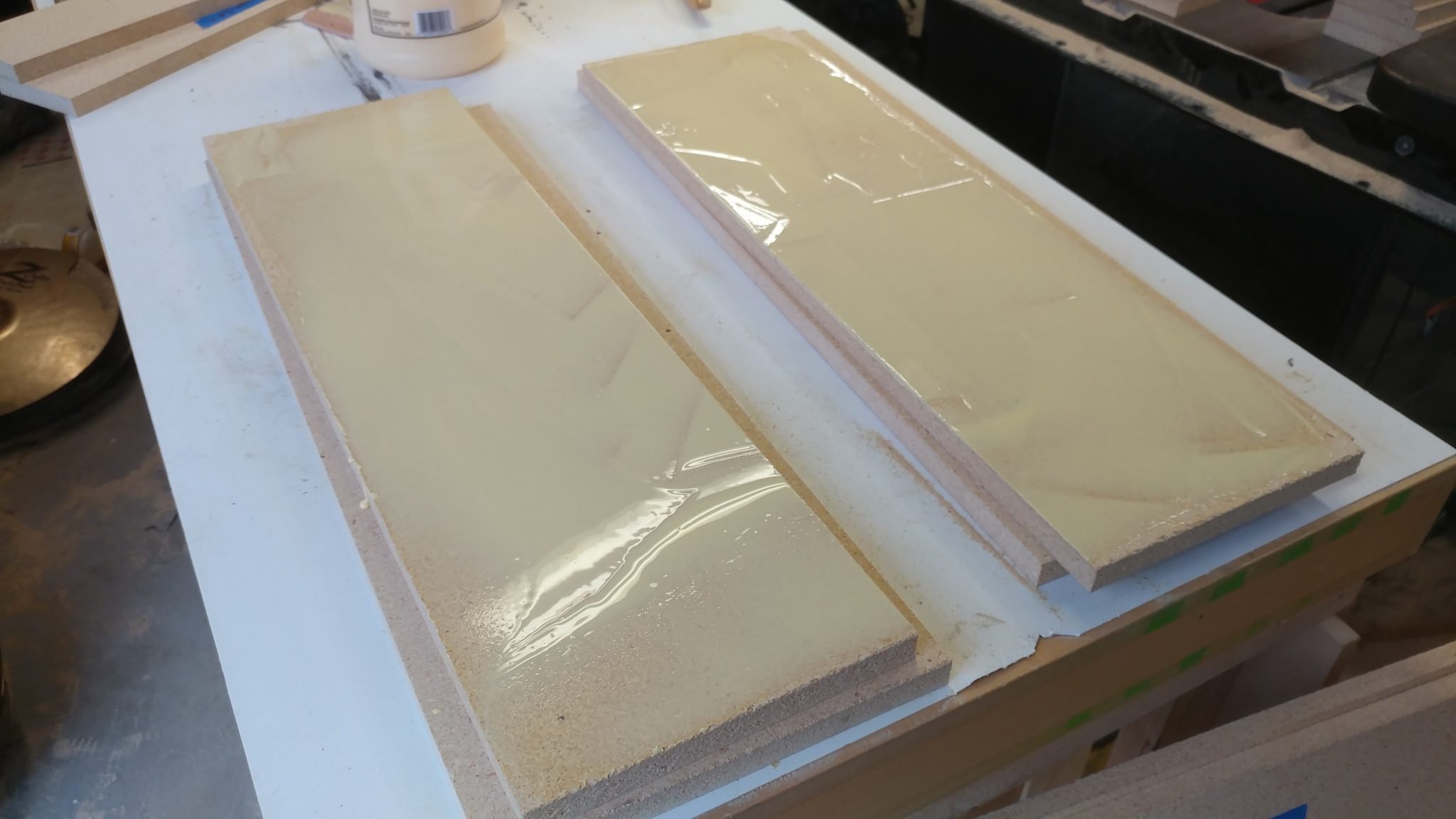
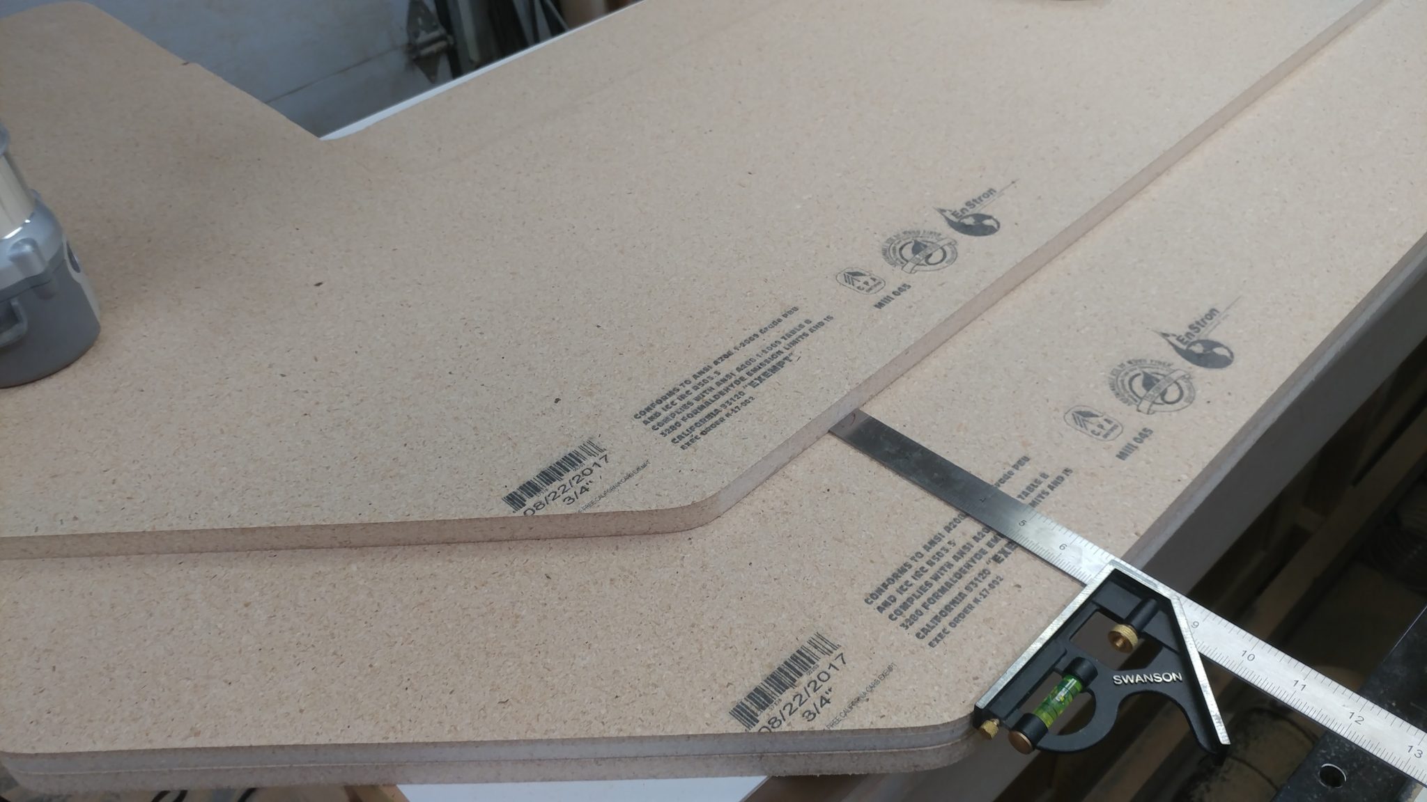
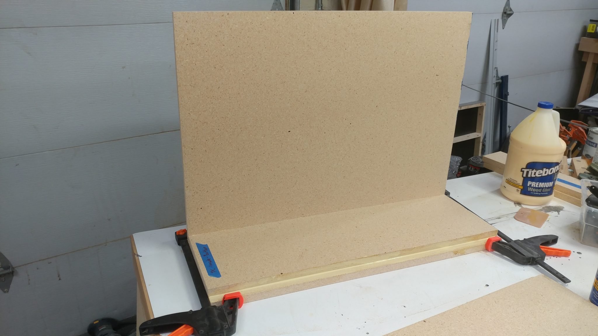
…then flip them over and lay them on the outsides.  I used a scrap piece of 3/4″ particleboard up against the inside piece to ensure that they are positioned correctly.


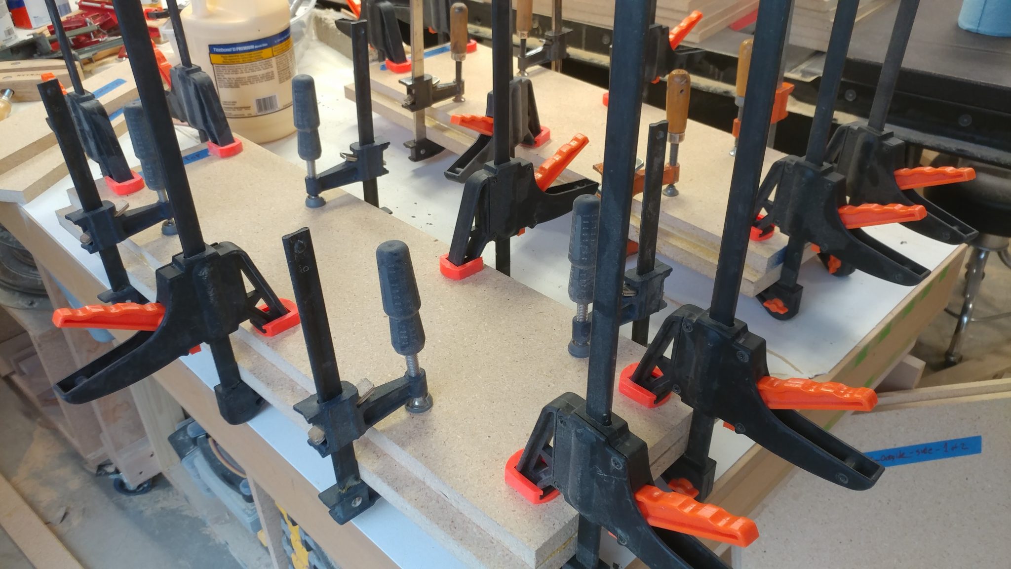
Then I clamped it all up and let them sit for about a half hour.


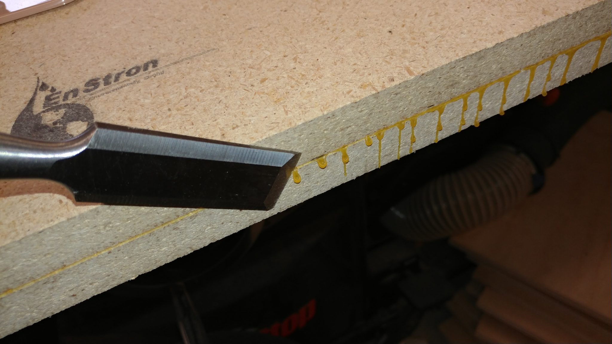
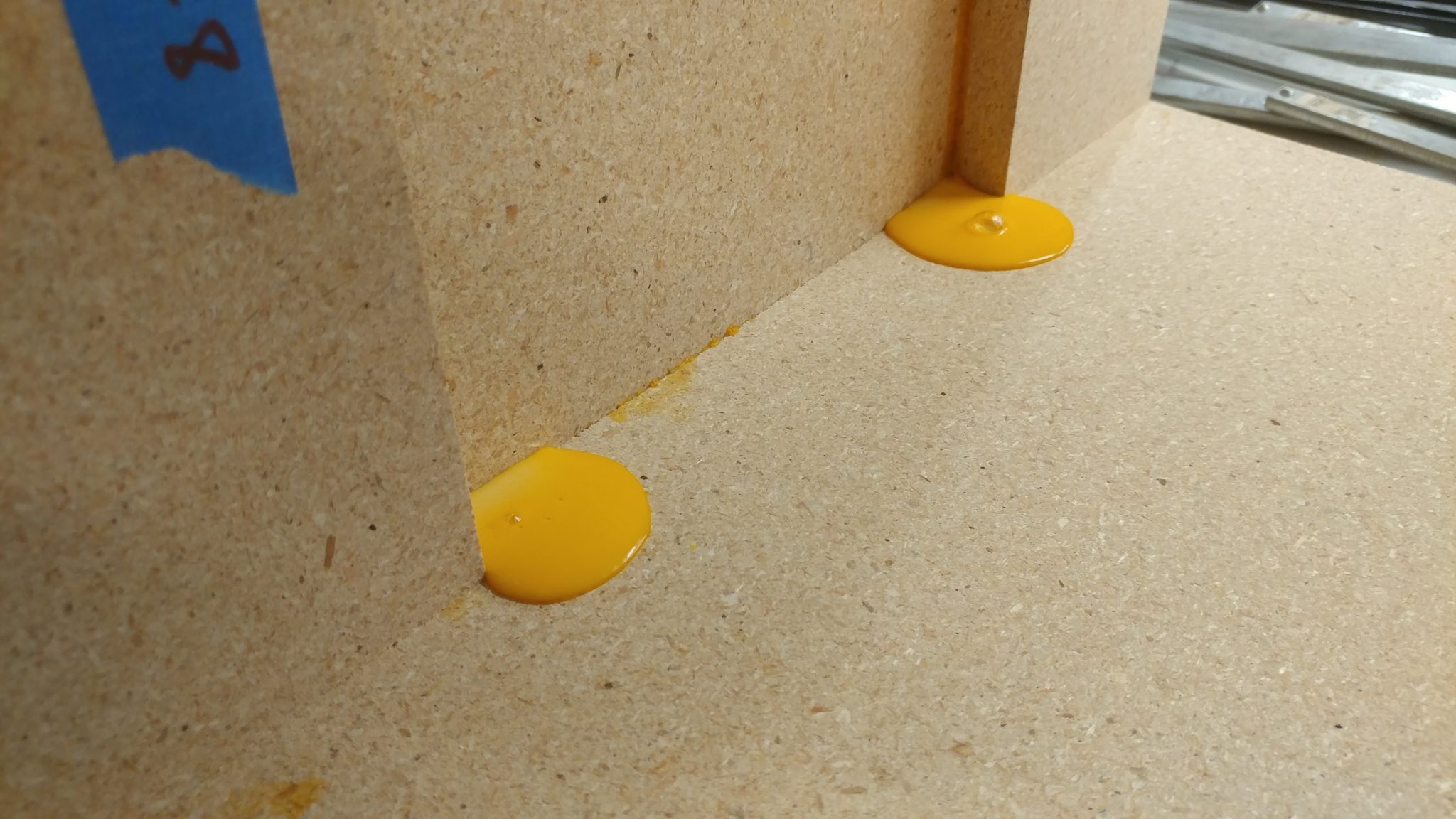
I tend to over-glue (as you’ll see in a bit) so there is usually some squeeze-out that I have to clean up.  For particle board I prefer to let it cure quite a bit then come back with a chisel to take the glue beads off. In this case I wasn’t allowing enough time for the glue to cure so I had some messy blobs to work around.  This wasn’t a problem as you’ll see in the next step.


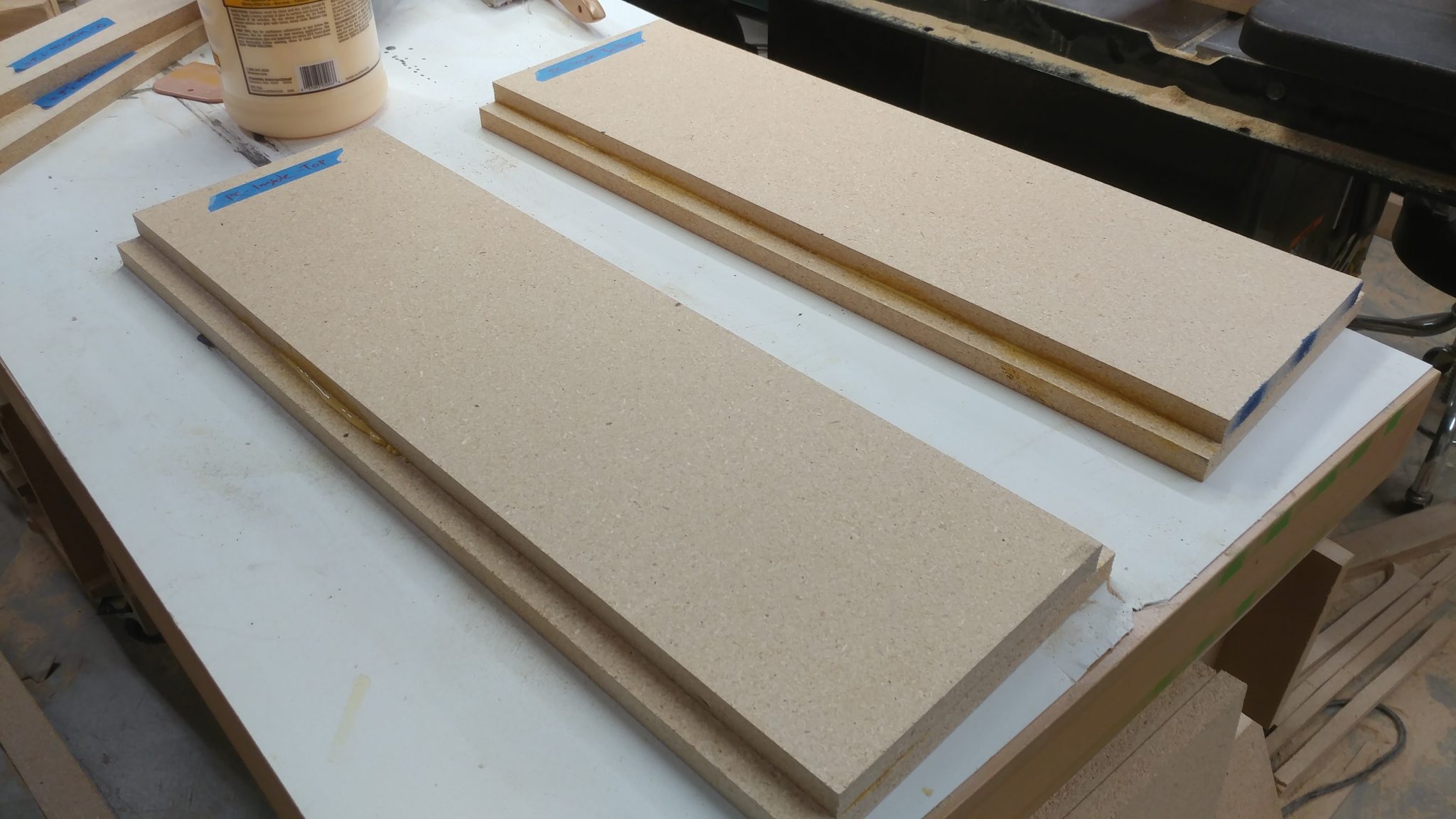
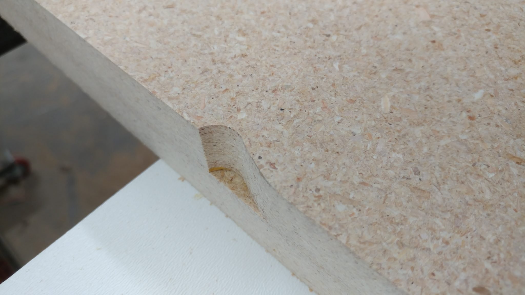
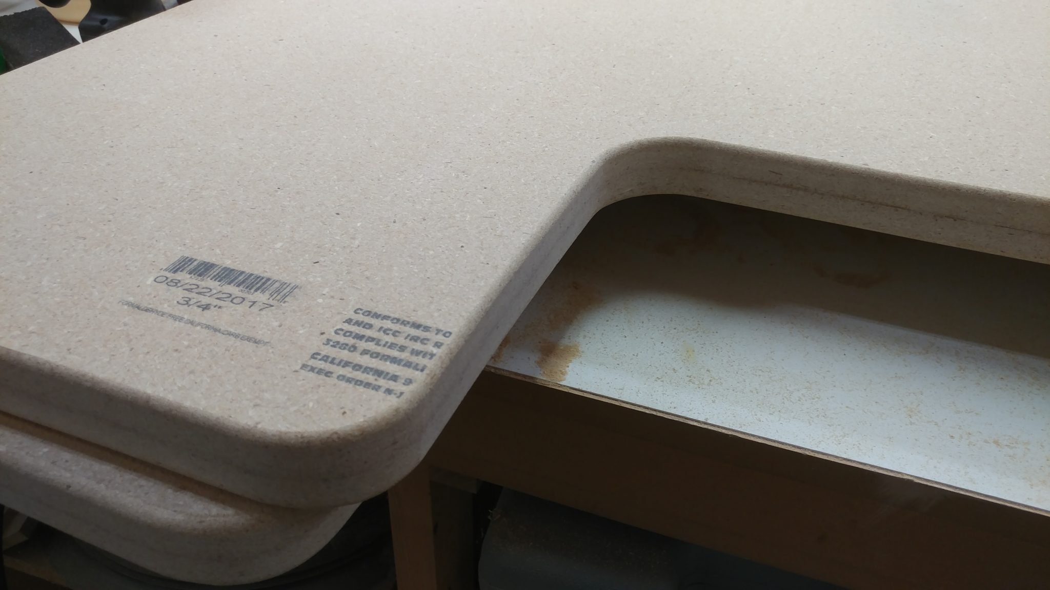
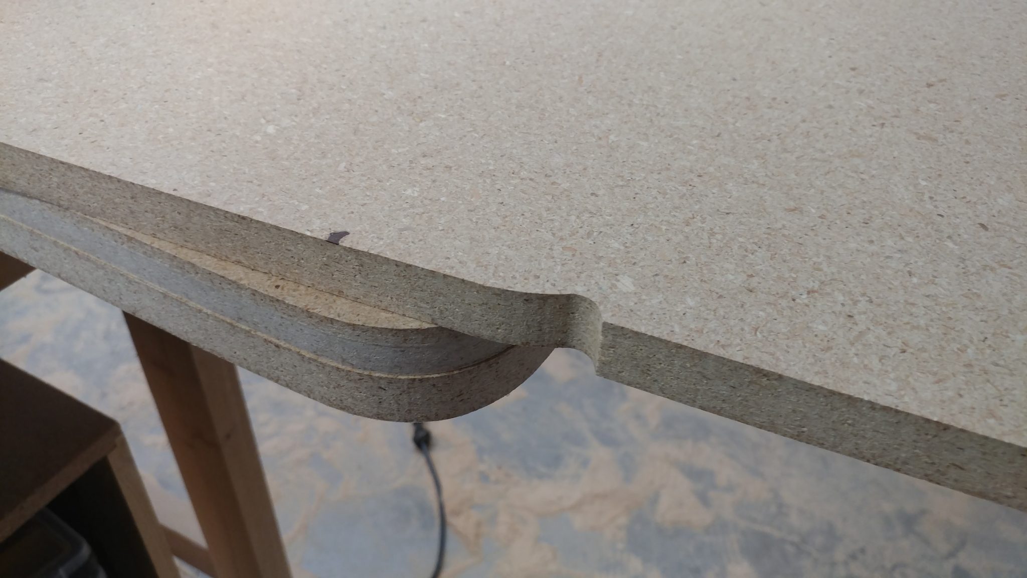
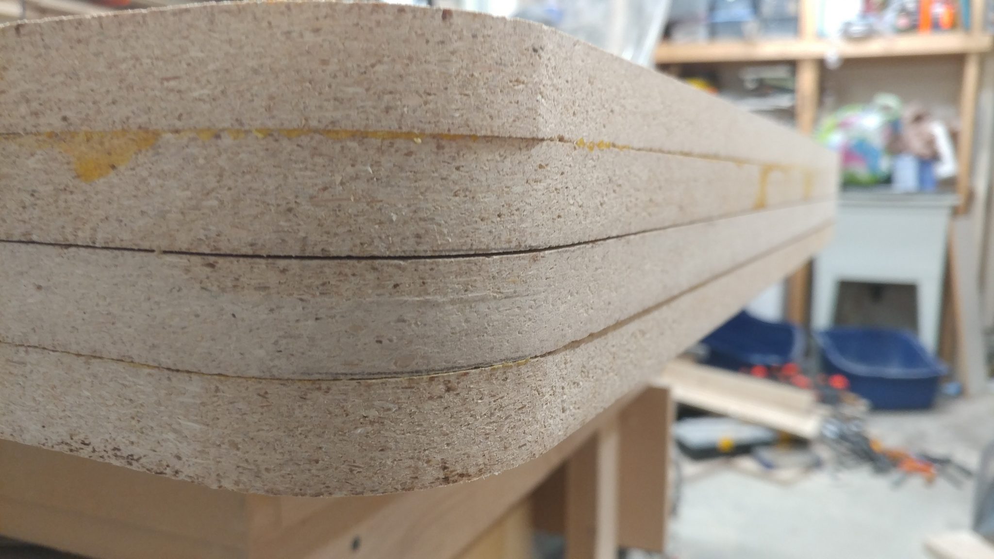
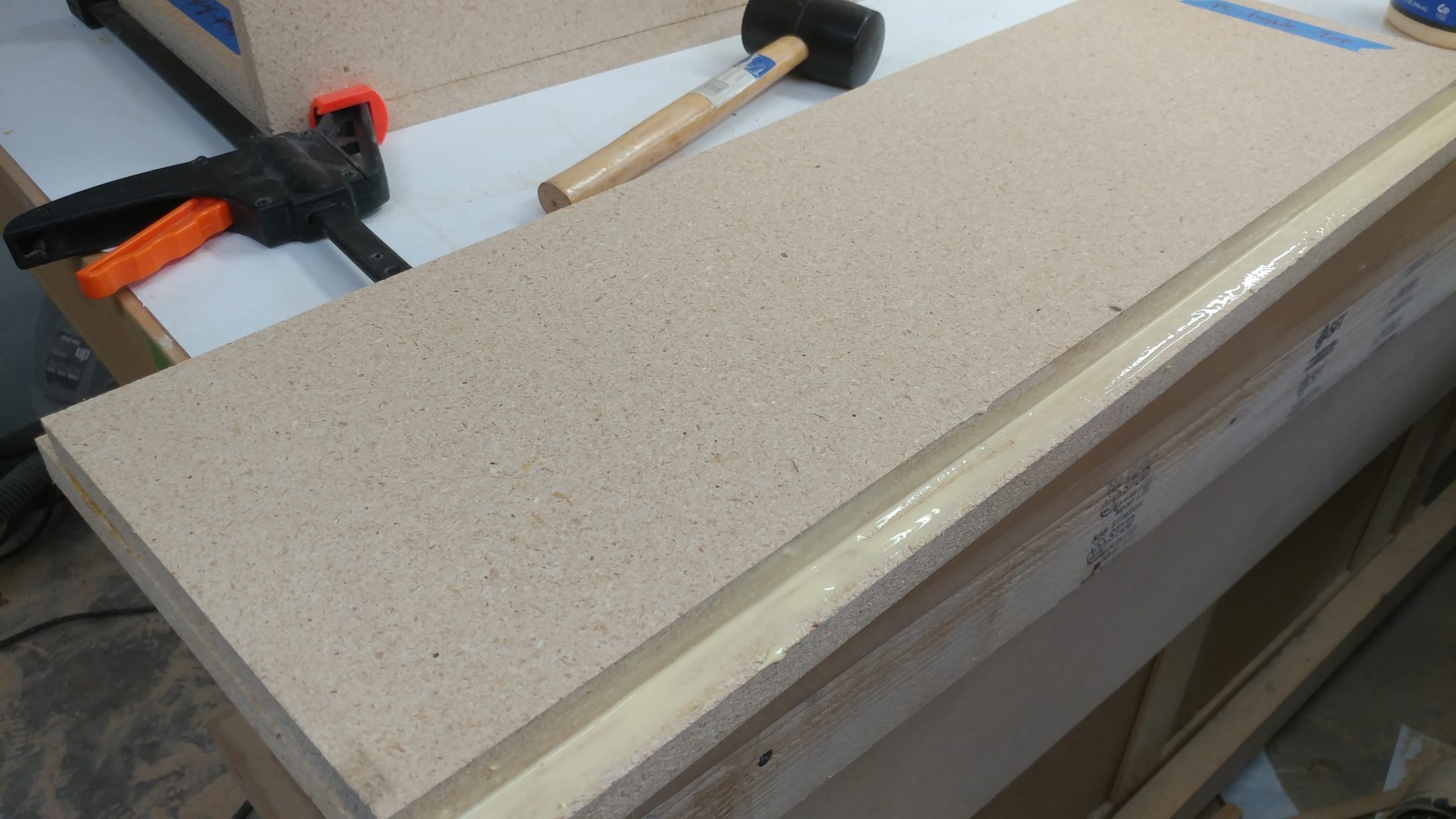
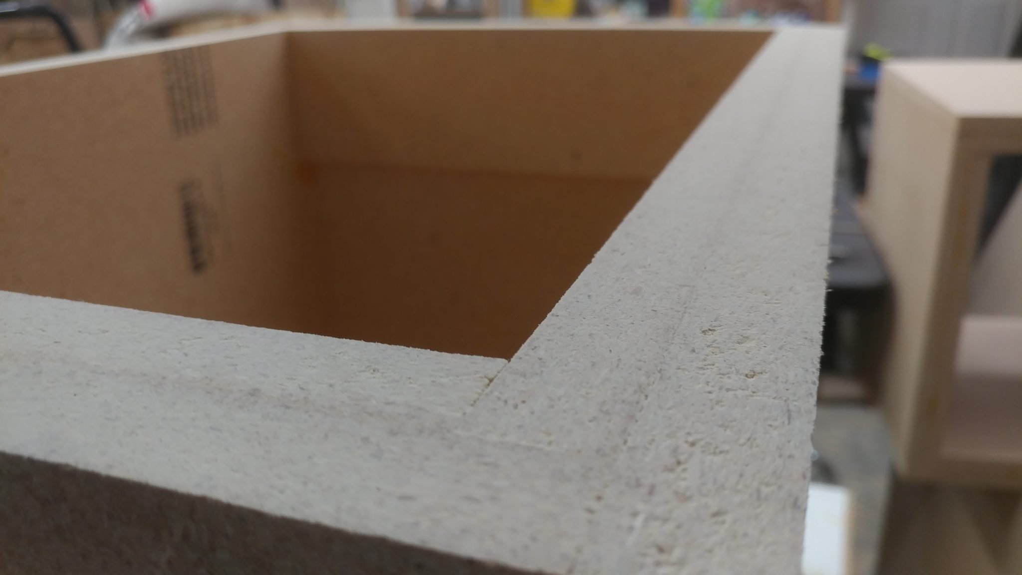
The two pieces glued up effectively make a piece that is 1-1/2″ thick with a 3/4″ X 3/4″ rabbet along two edges.  I applied glue along these edges so I could attach the sides.


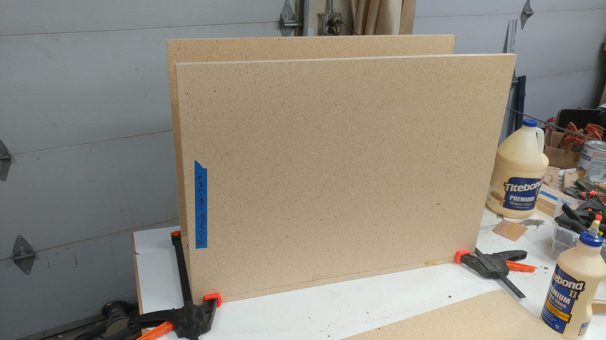
I used quick release clamps to hold one side in place while I maneuvered the second side in place.


The same quick-release clamps held both sides in place so I could drop the top assembly in place.


The top is just like the bottom so I added glue to the rabbets.


I dropped the top part in place and  kept the clamps loose enough so I could  nudge the pieces so they were well aligned.


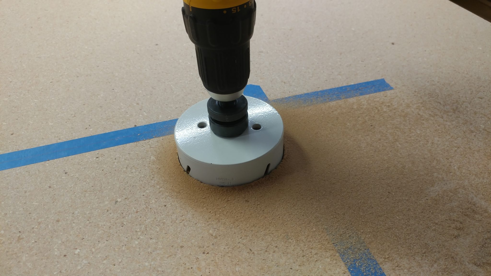
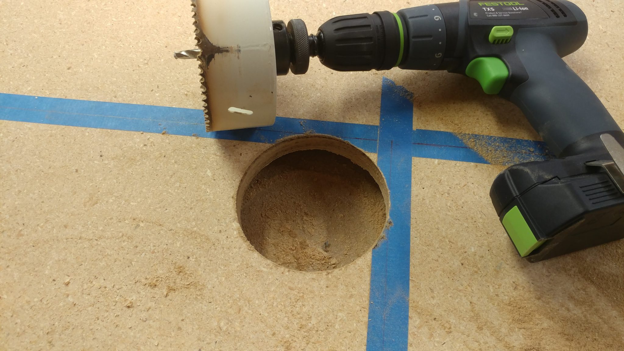
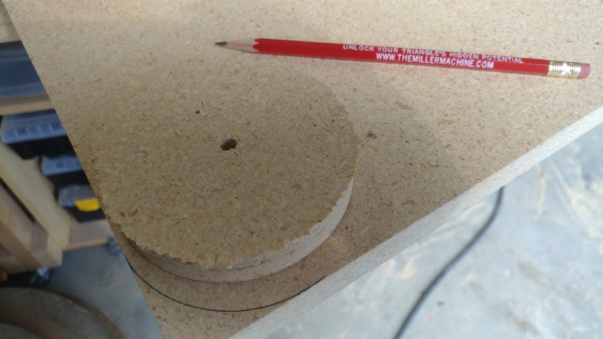
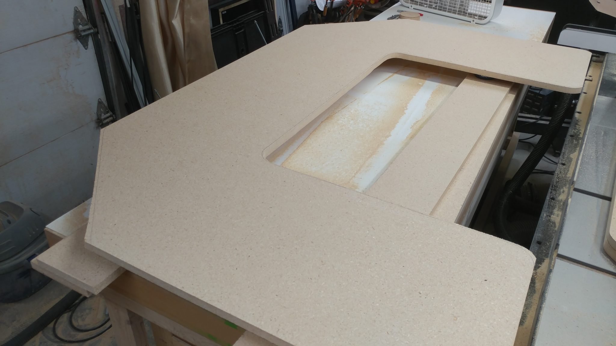
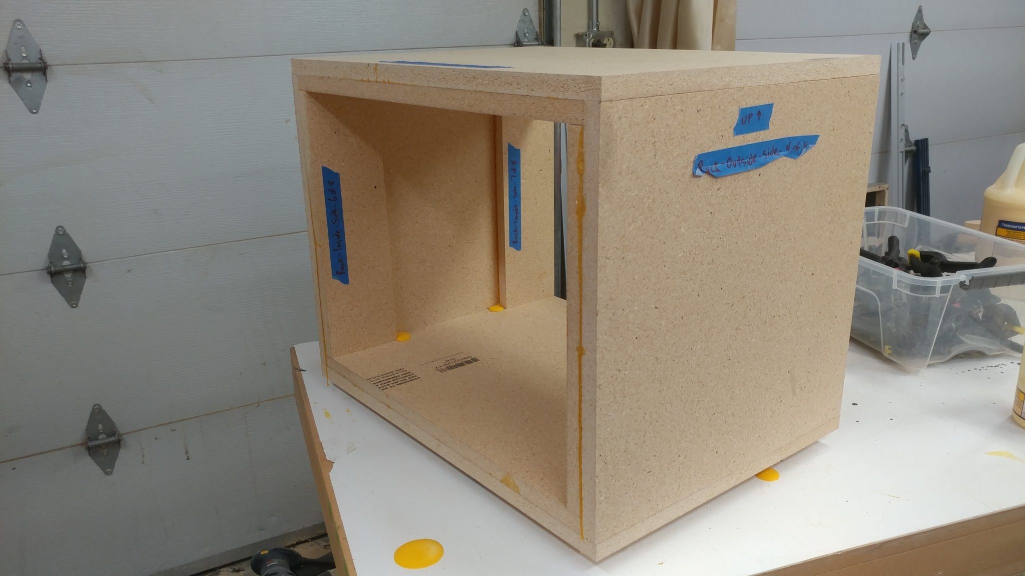
Rather than make the side pieces on the inside of each rack the entire length of the rack itself, I made them 4″ wide.  This will accomplish a few things.  It will lighten each rack a bit, although they still weigh a ton.  Mainly, they will aid with airflow.  Also, I’m installing cable pass-through grommets and they work best when the material they are going through is 3/4″ thick.  I cut four pieces for the sides of each rack and slathered on the glue.


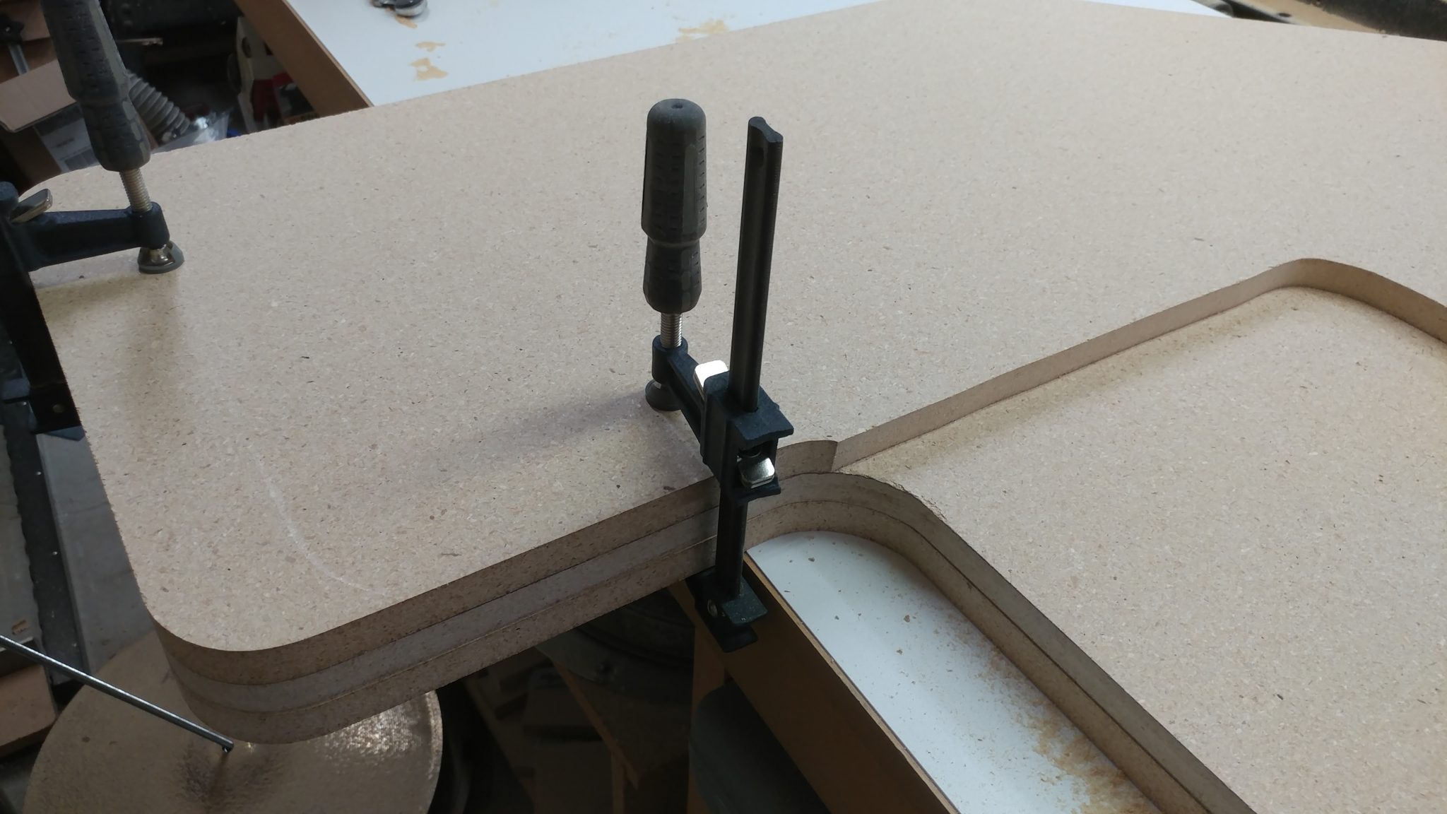
I then clamped them in place.


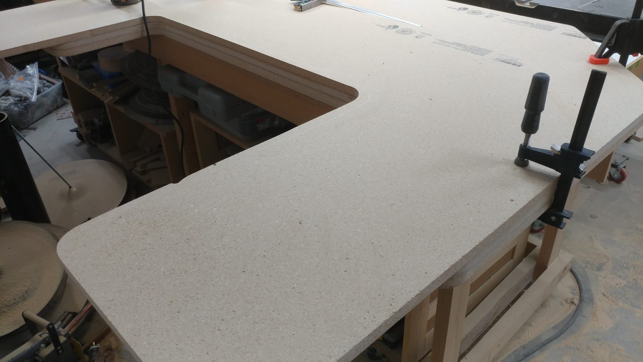
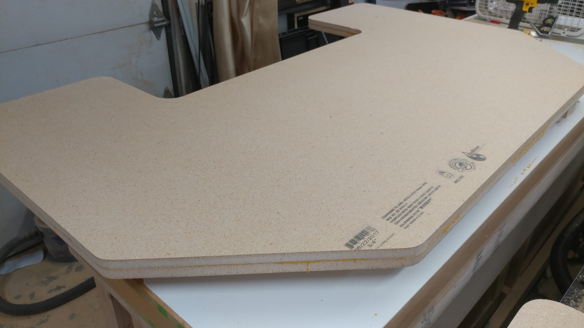
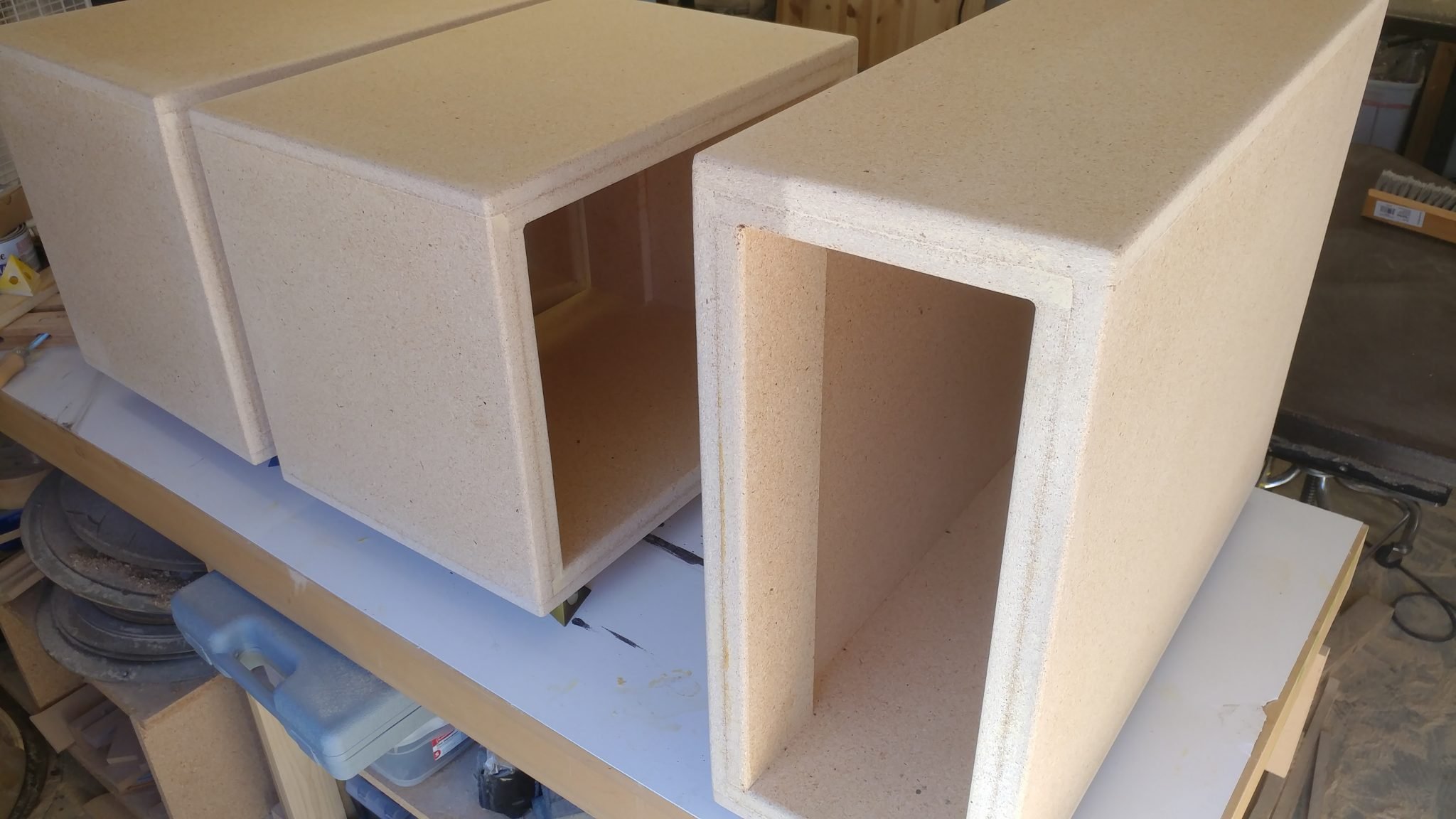
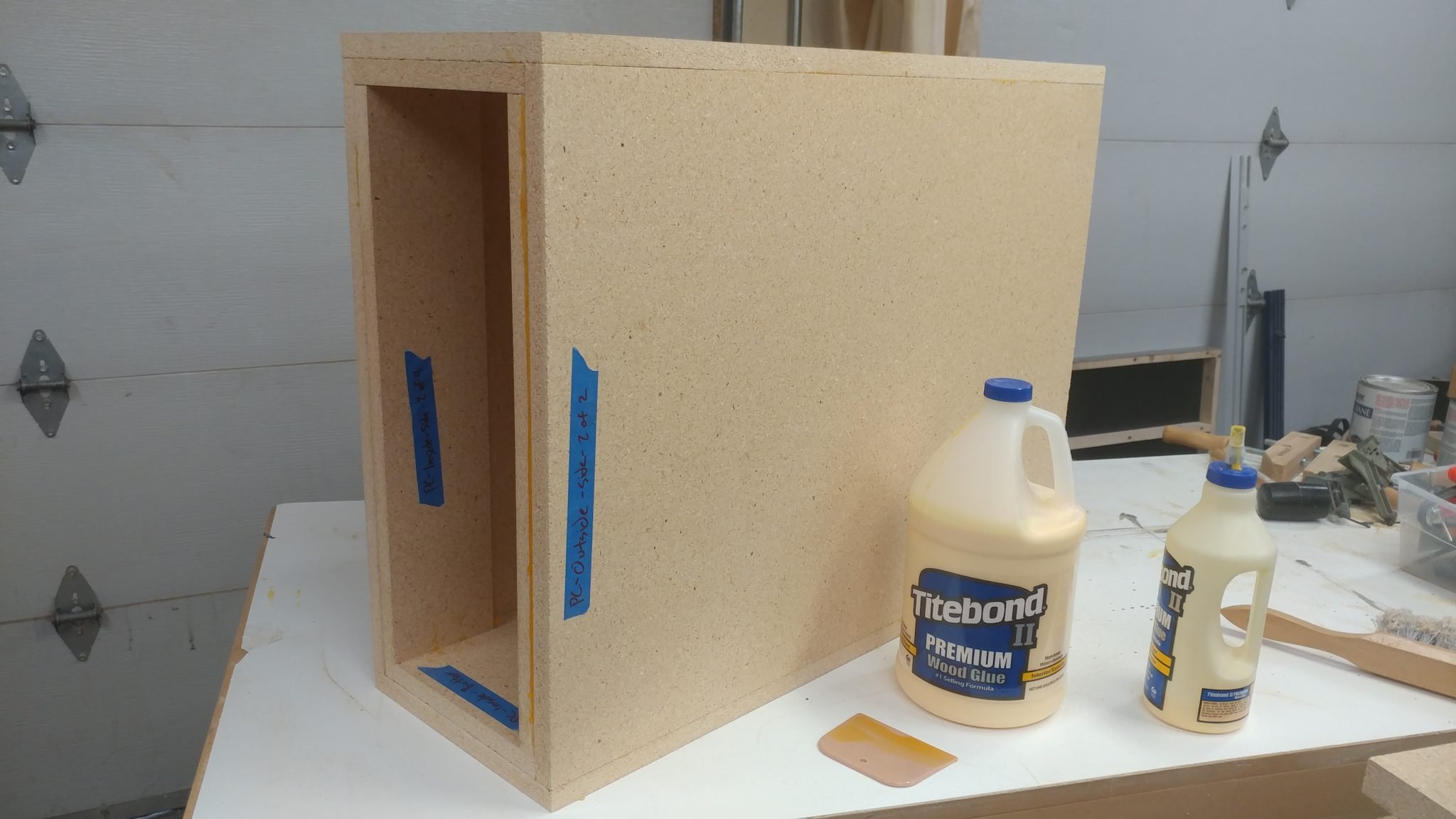
After letting it sit overnight, the PC rack is assembled and ready to be shaped and cleaned up.


Assembling the Two Racks

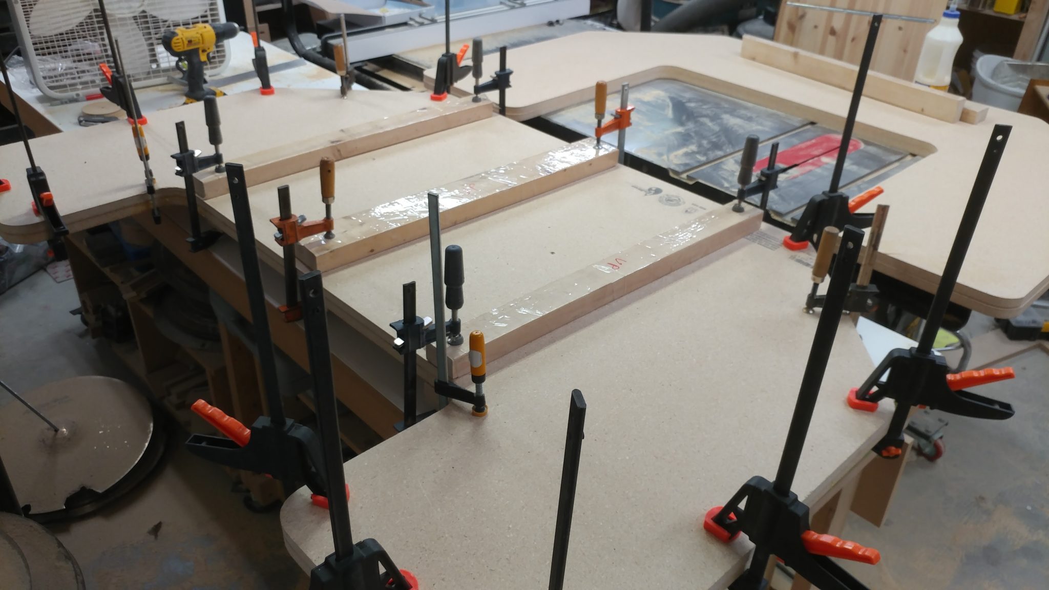
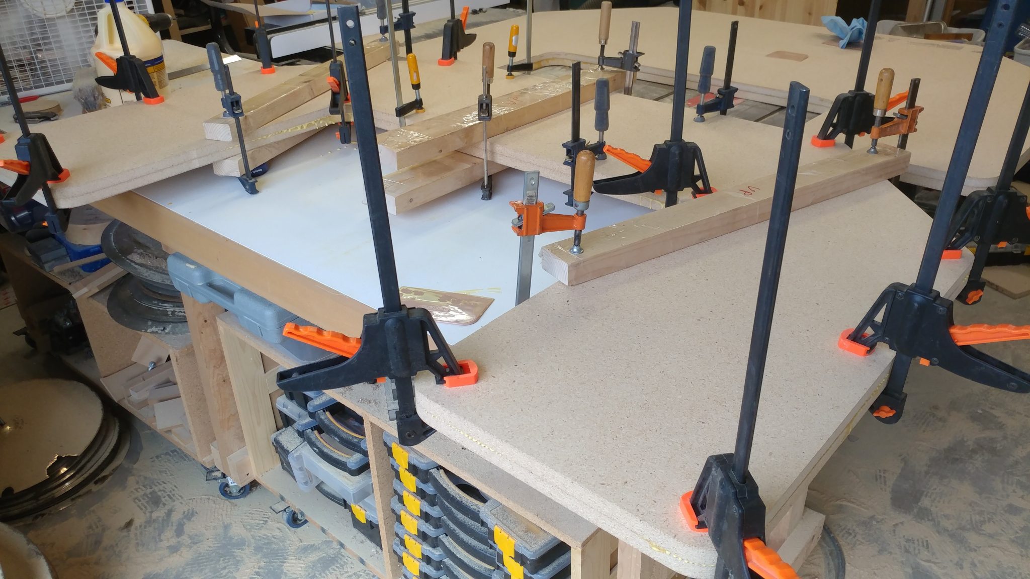
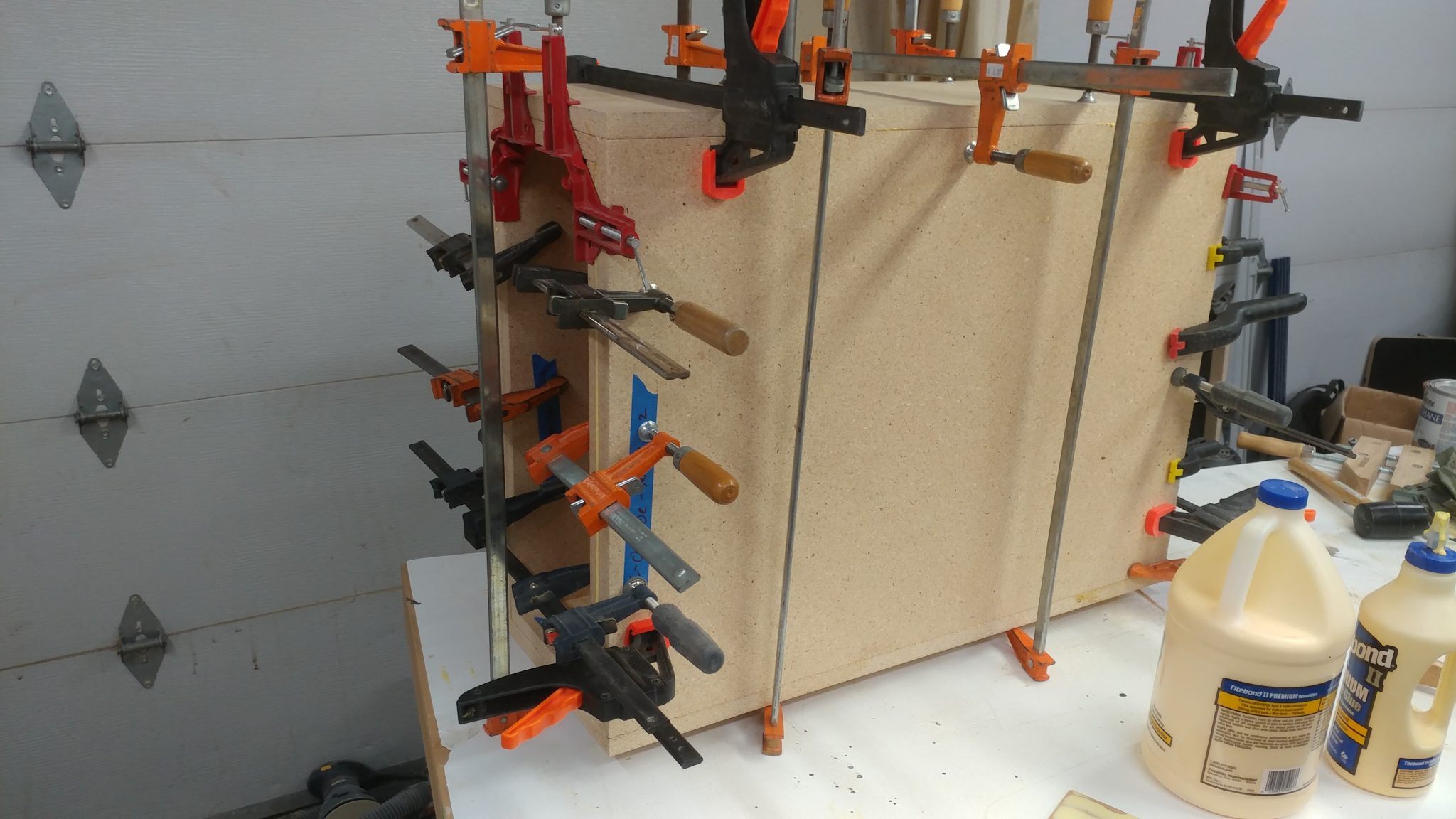
I then repeated the process for the equipment racks.  The tops and bottoms were glued up and ready to be assembled with the sides.


Lots and lots of clamps were used for the assembly since I am relying on glue to hold this all together.


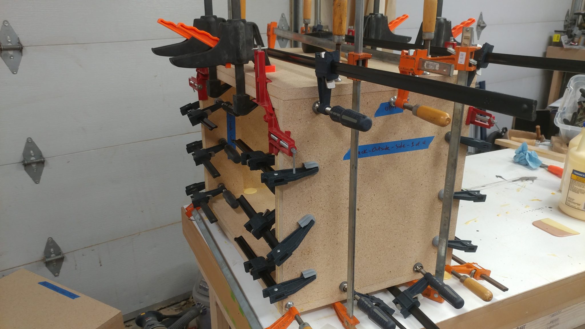
As you can see, I got a little crazy with the wood glue.  It cleans up easy enough and shouldn’t interfere with the finish at all.


Too much glue is better than not enough.


Cleaning up the Racks

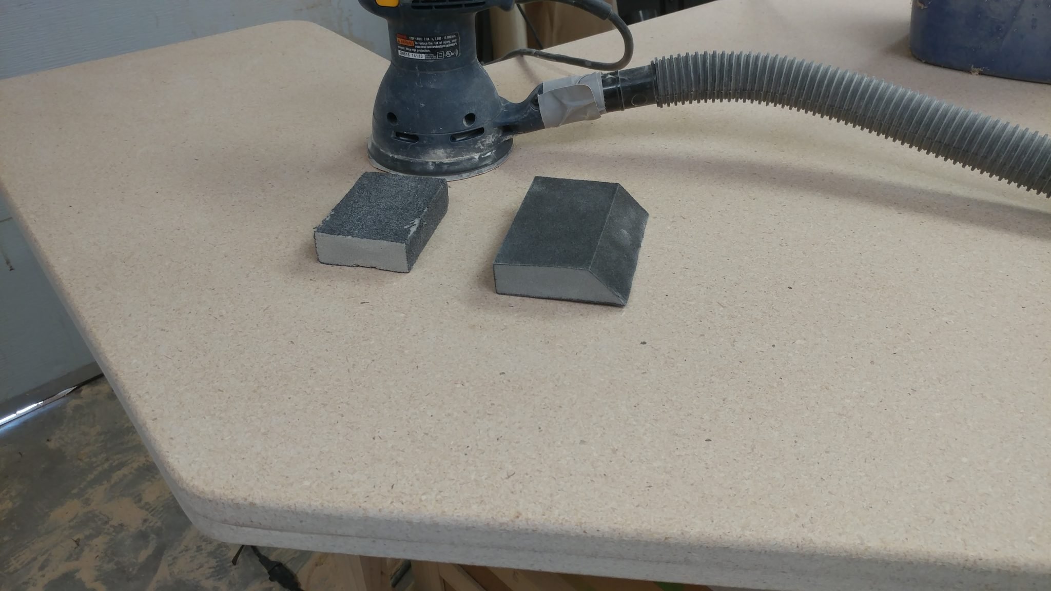
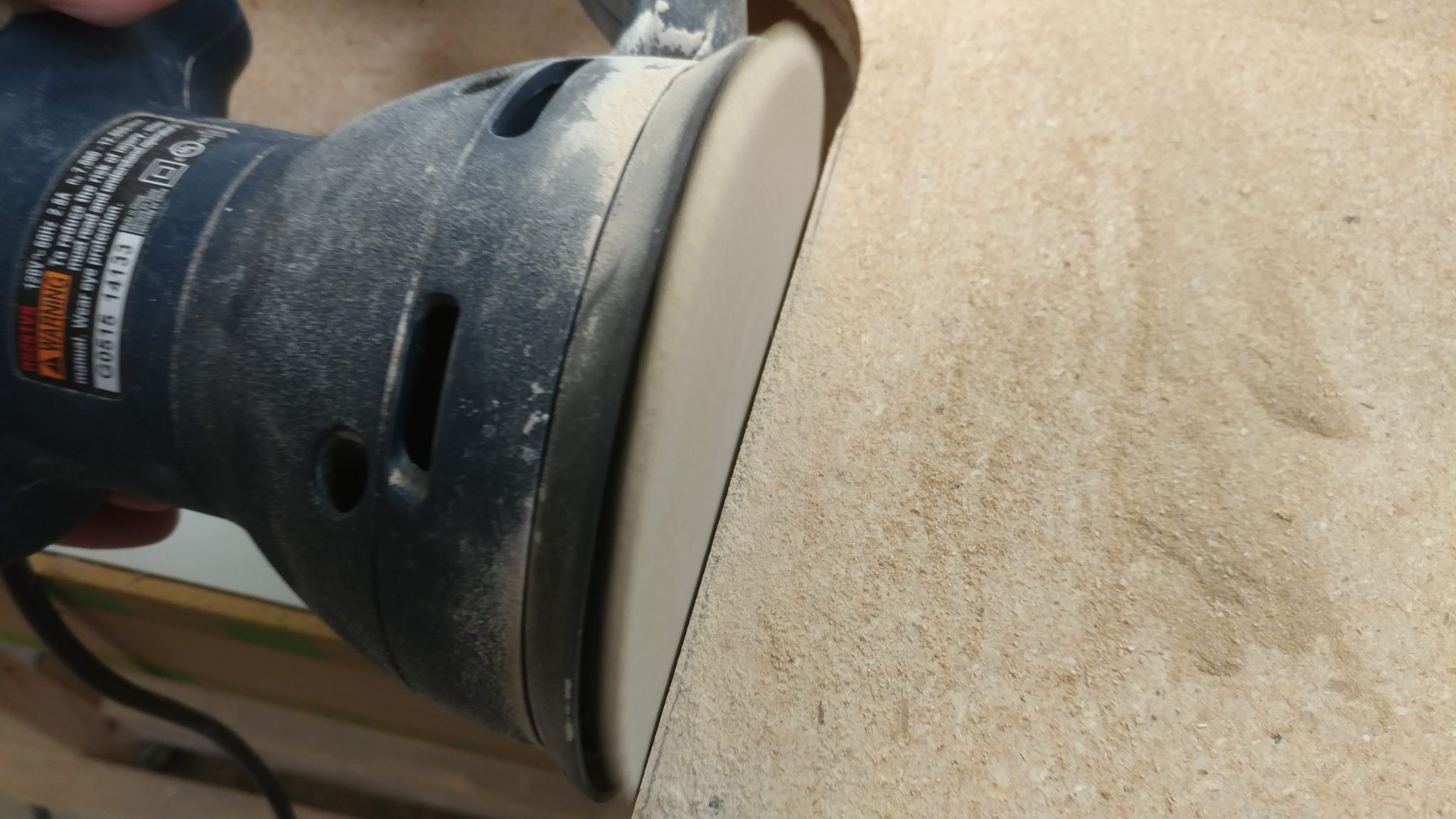
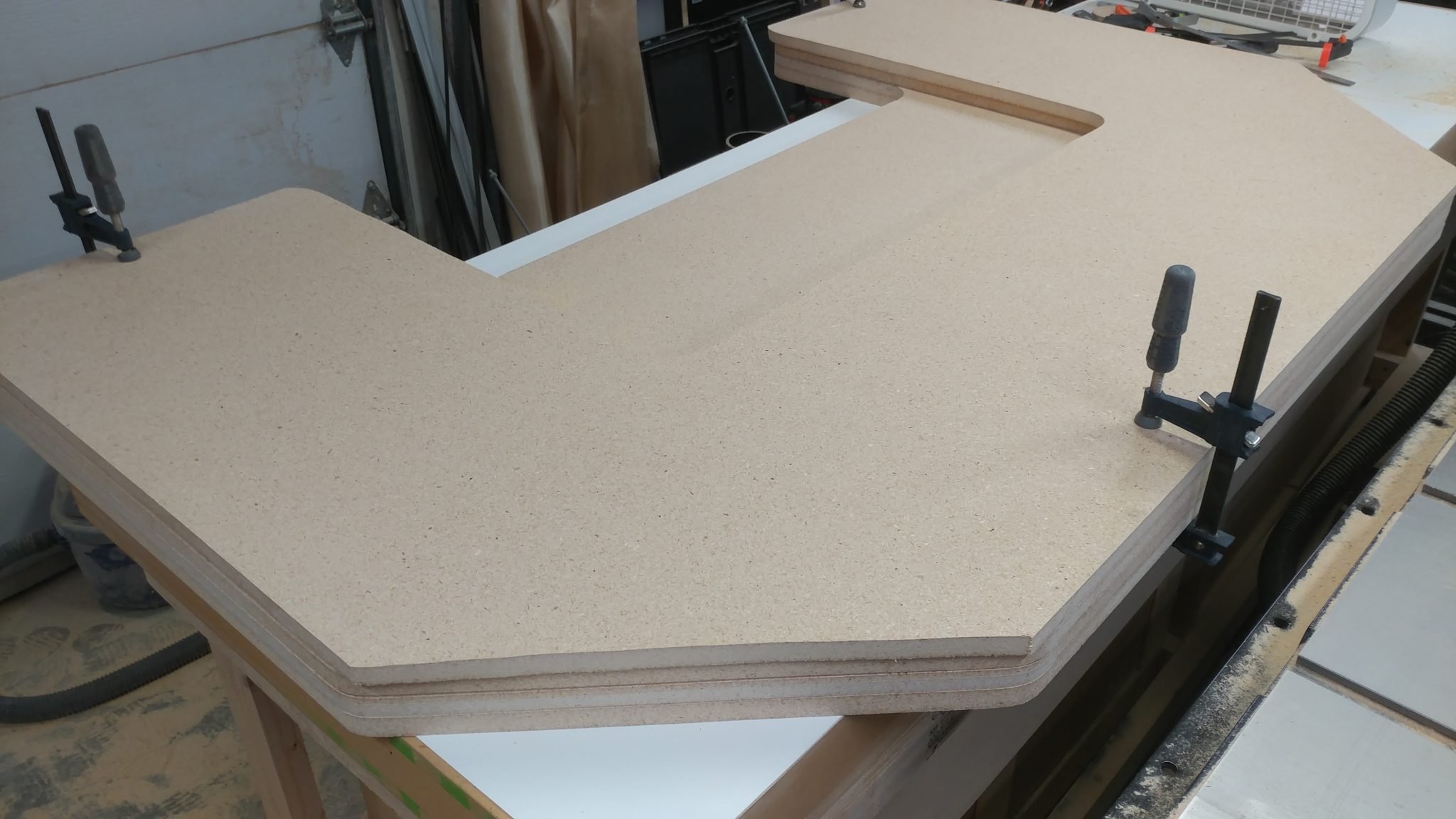
I used a random orbital sander to clean up the edges on one face of each rack.


I also cleaned up the tops and bottoms.


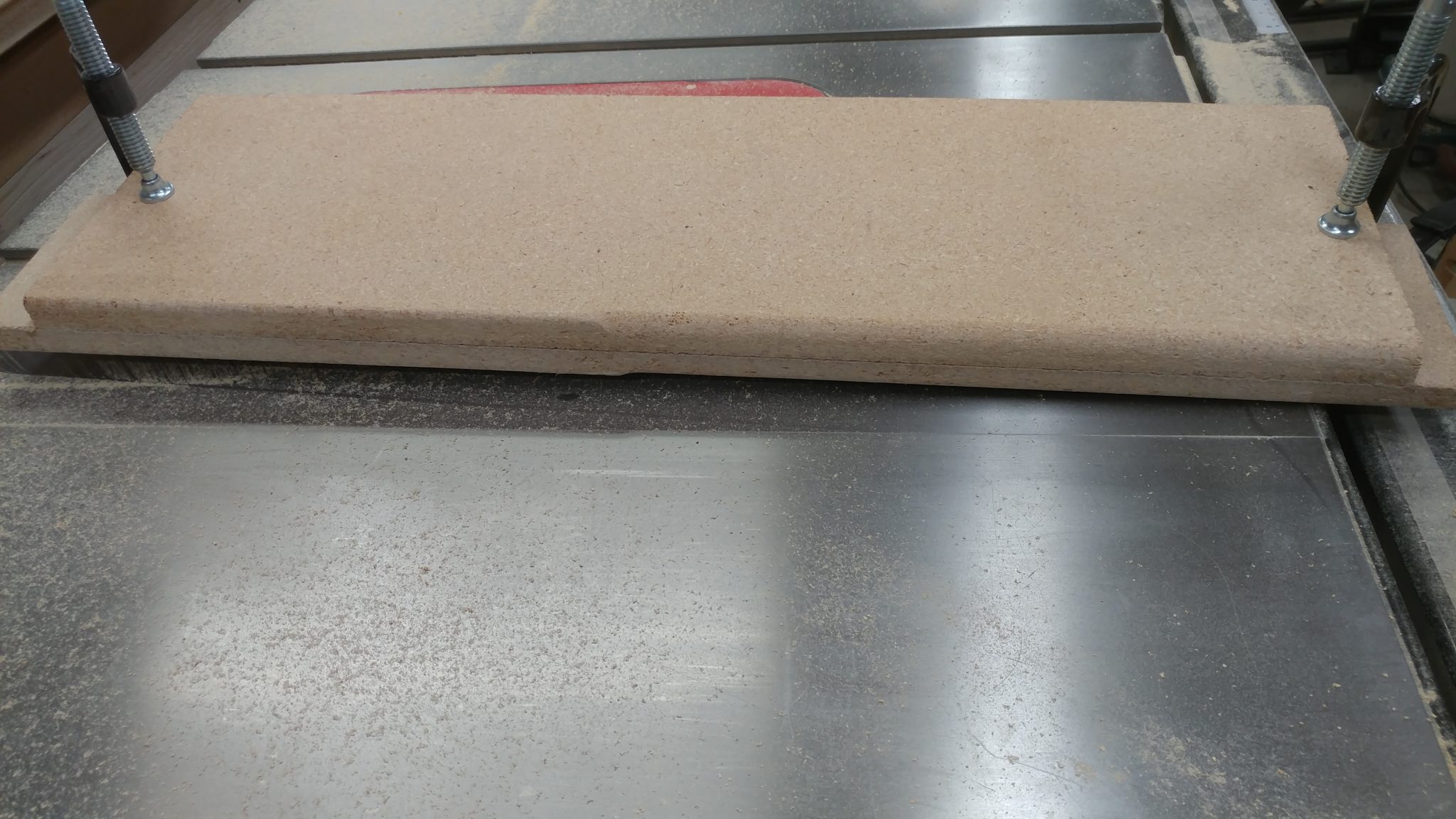
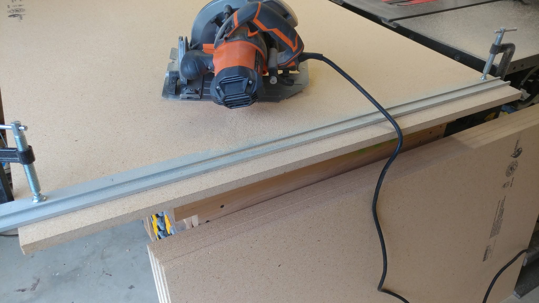
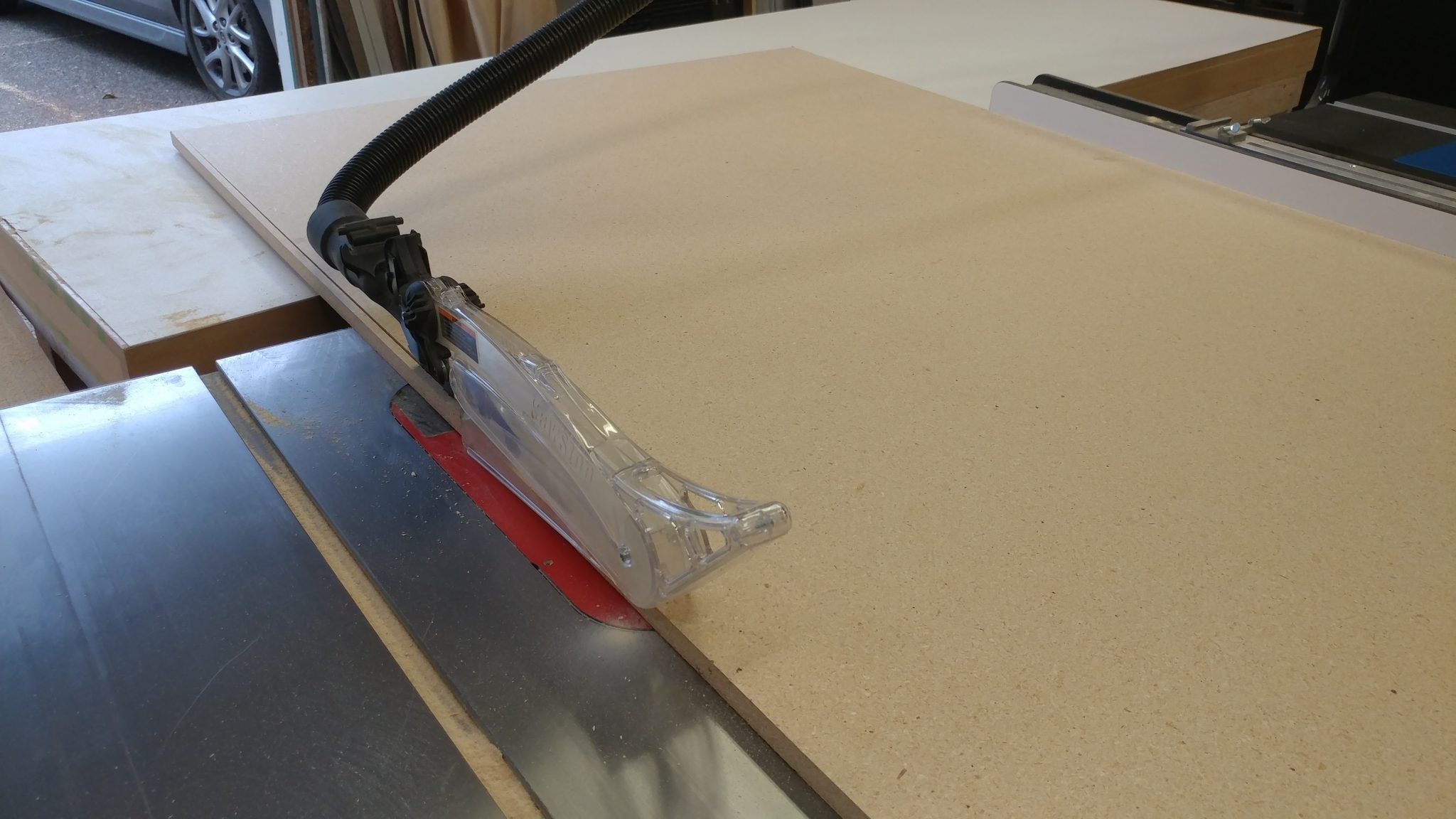
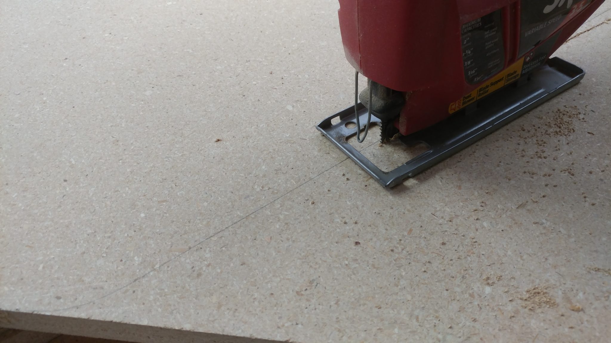
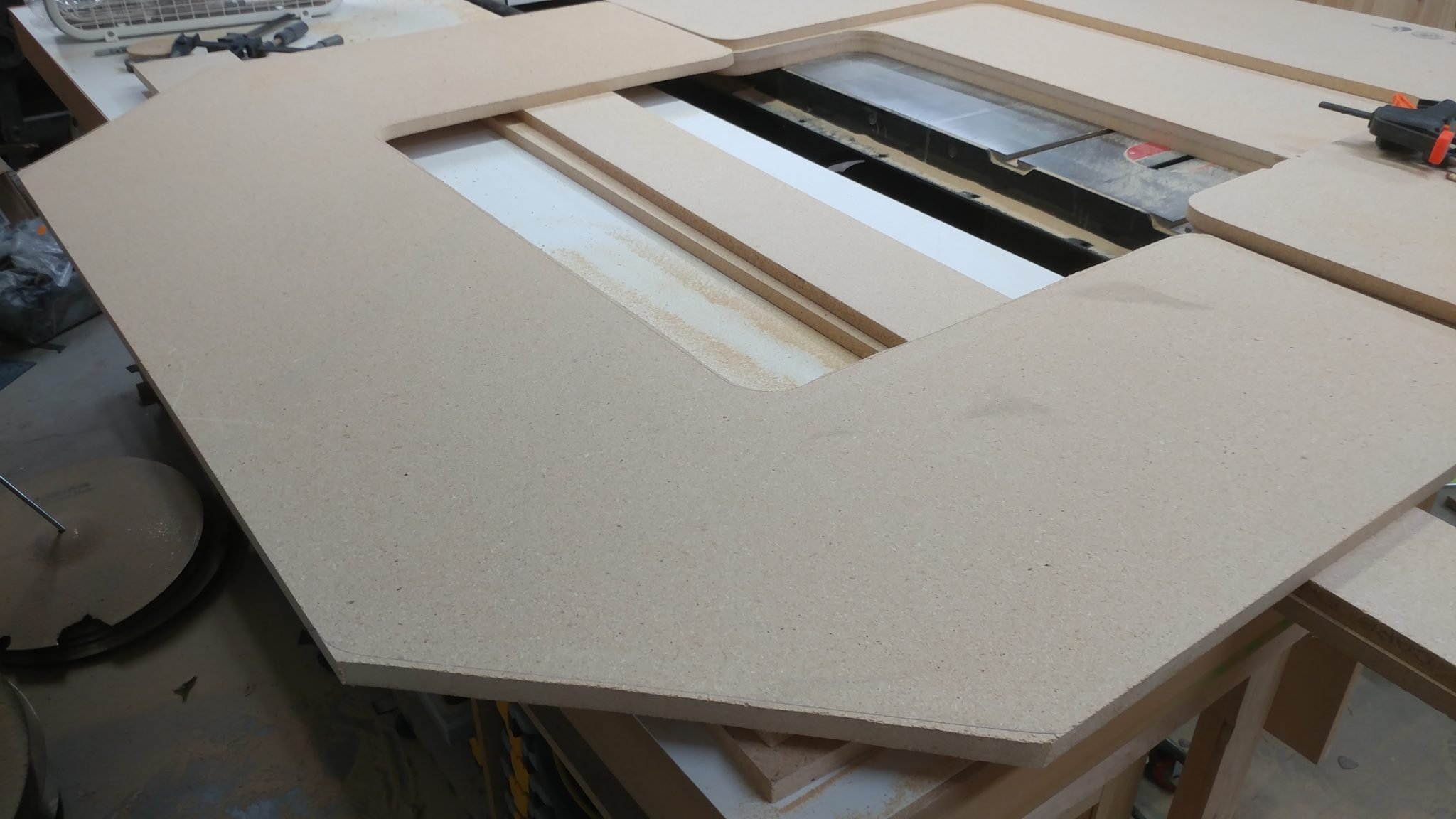
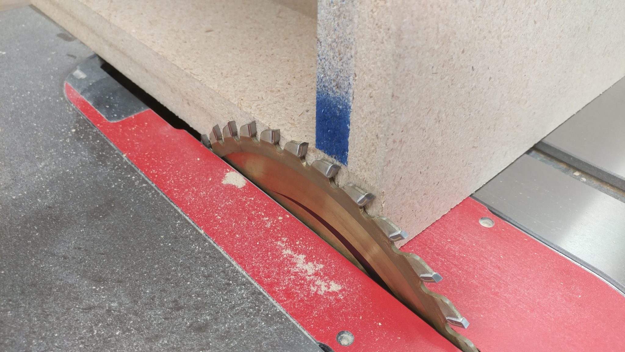
To clean up the final face, and to ensure that both of the equipment racks are the same depth, I shaved off the edge of the last side at the table saw.


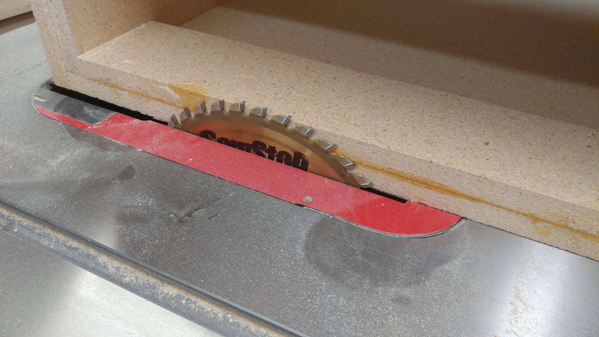
I shaved off just enough to clean up each edge.


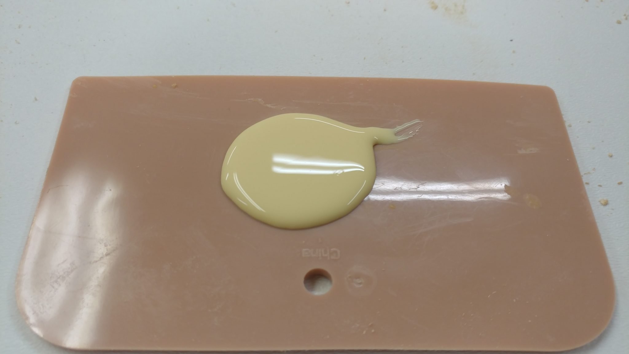
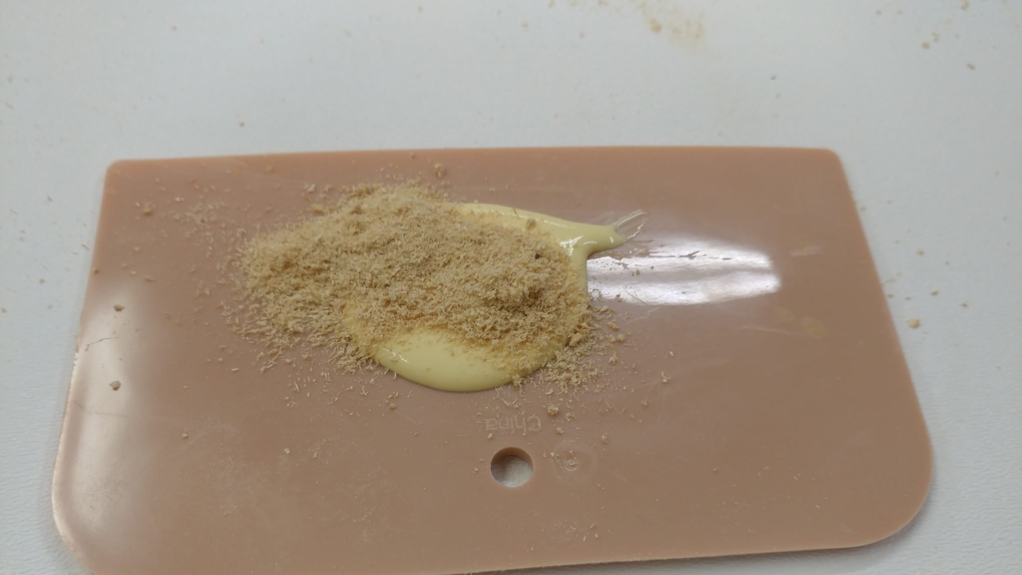
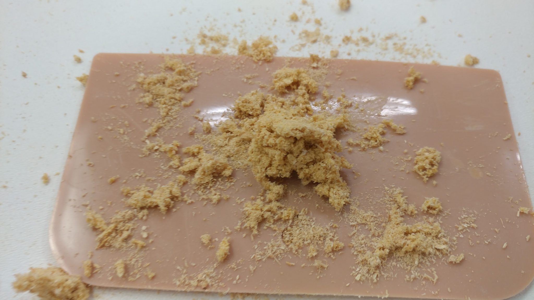
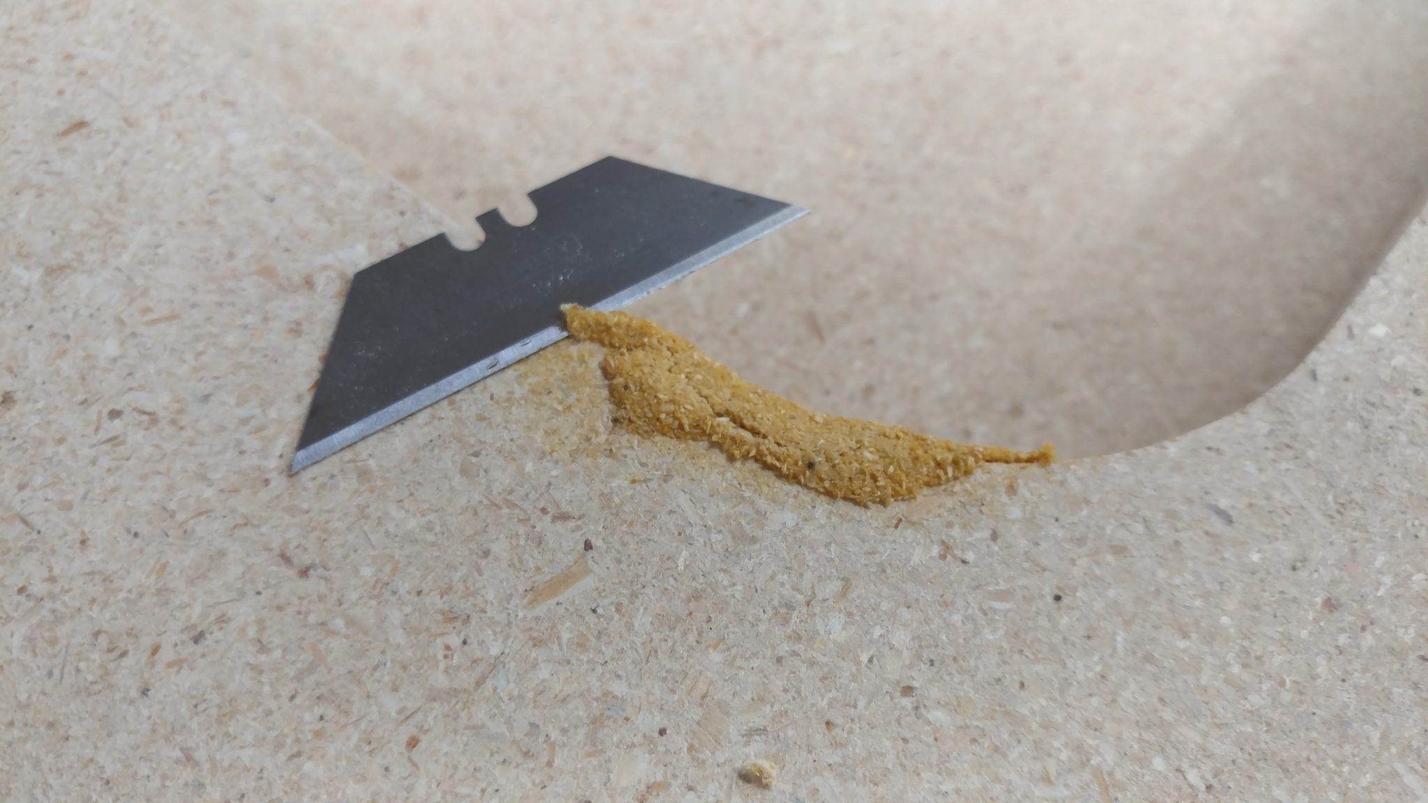
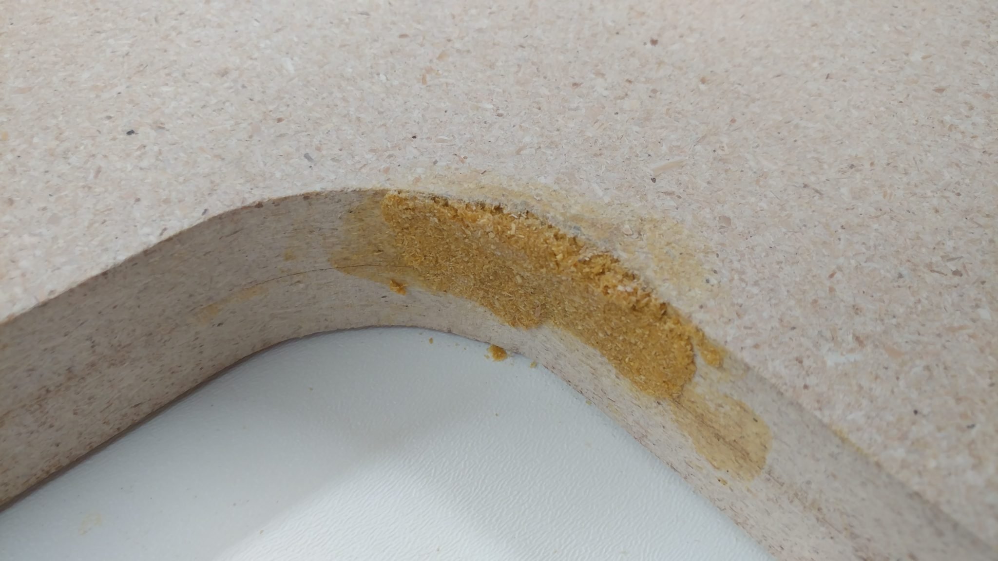
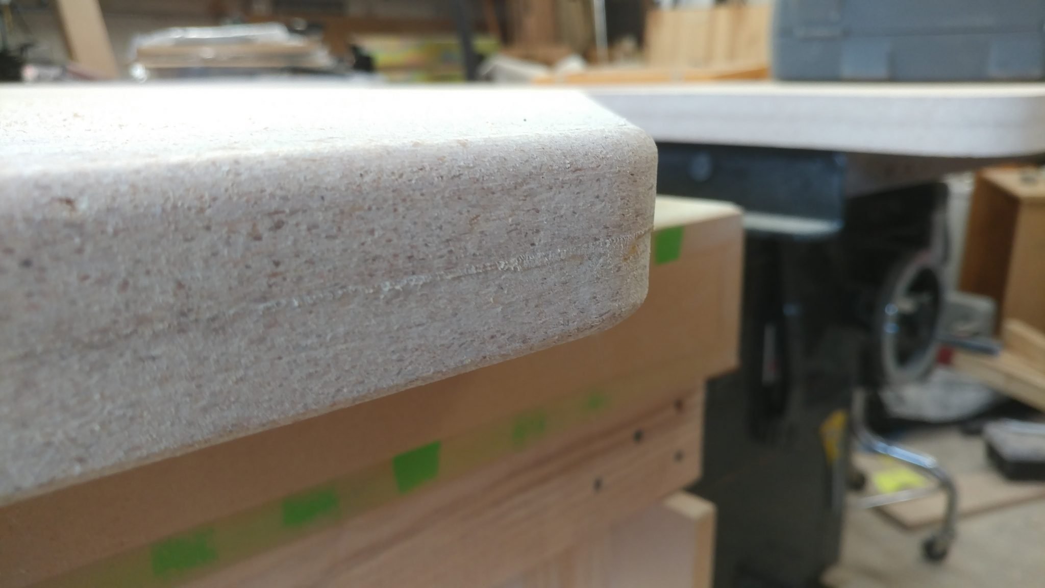
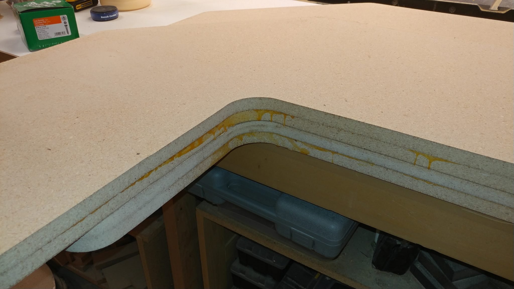
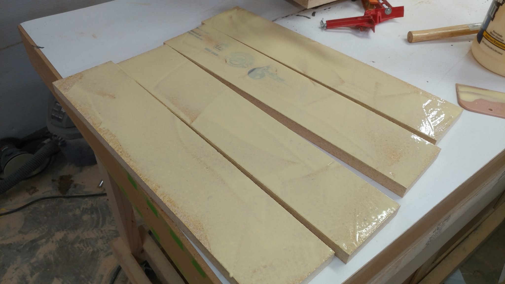
Once each face was clean, I decided to try something different.  I’m going for a rough industrial look with this.  I had seen a piece of furniture once that was made with MDF and had some (what I assume is) wood filler in certain parts.  The way that the filler reacted with the stain and finish had a really interesting rough look.  I decided that I would try this on the racks.  If I end up not liking it, I can always just remake the racks.


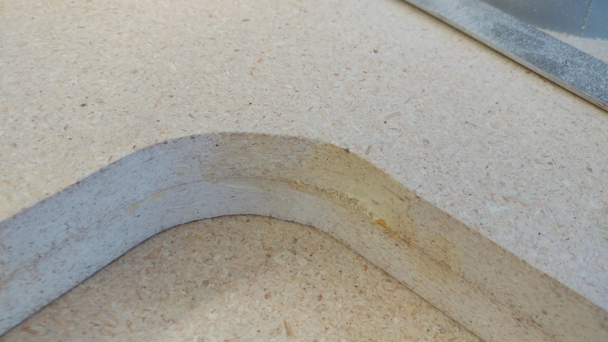
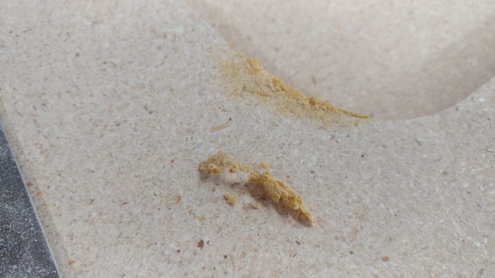
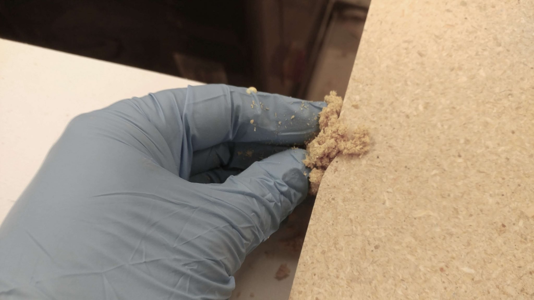
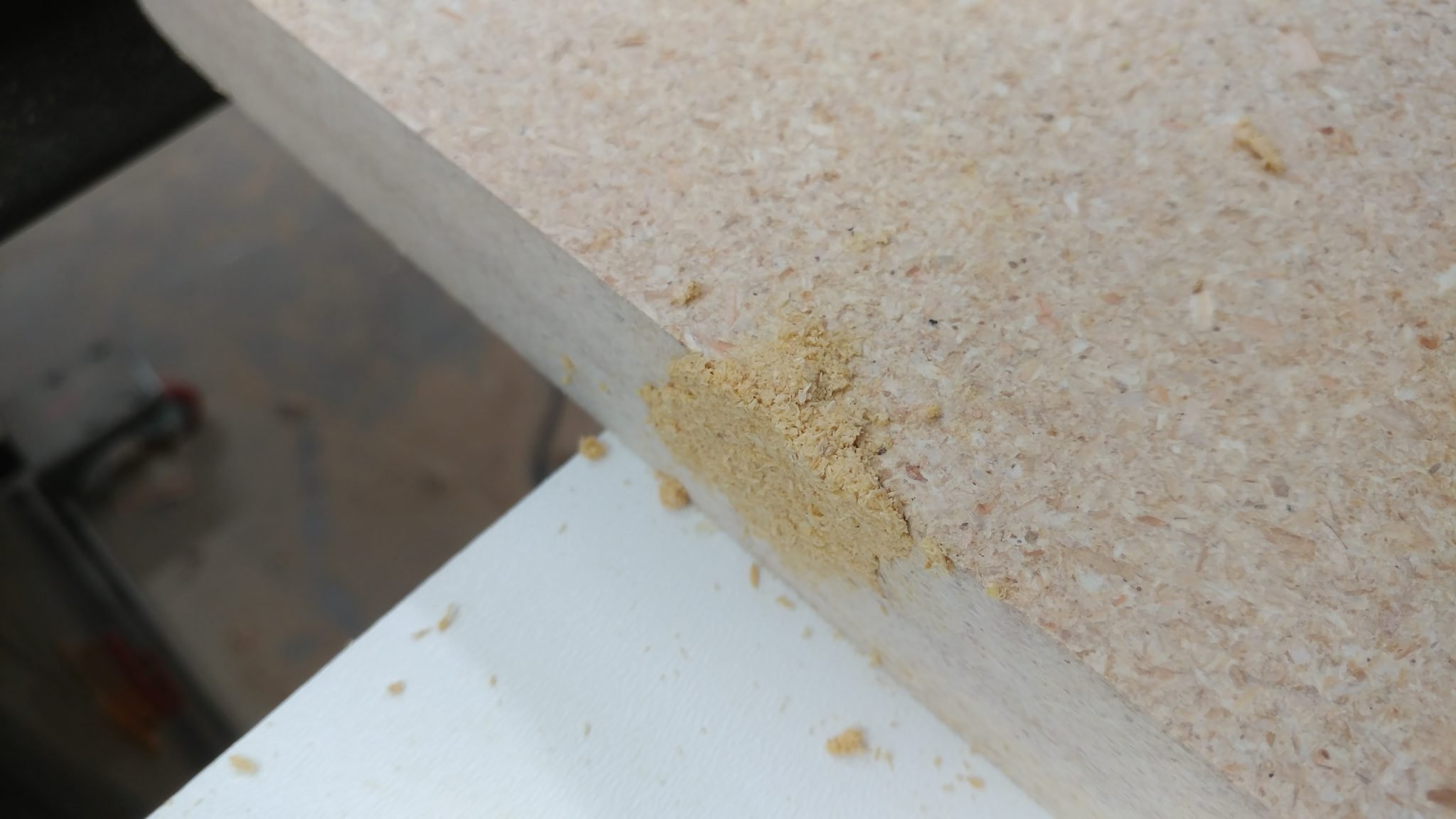
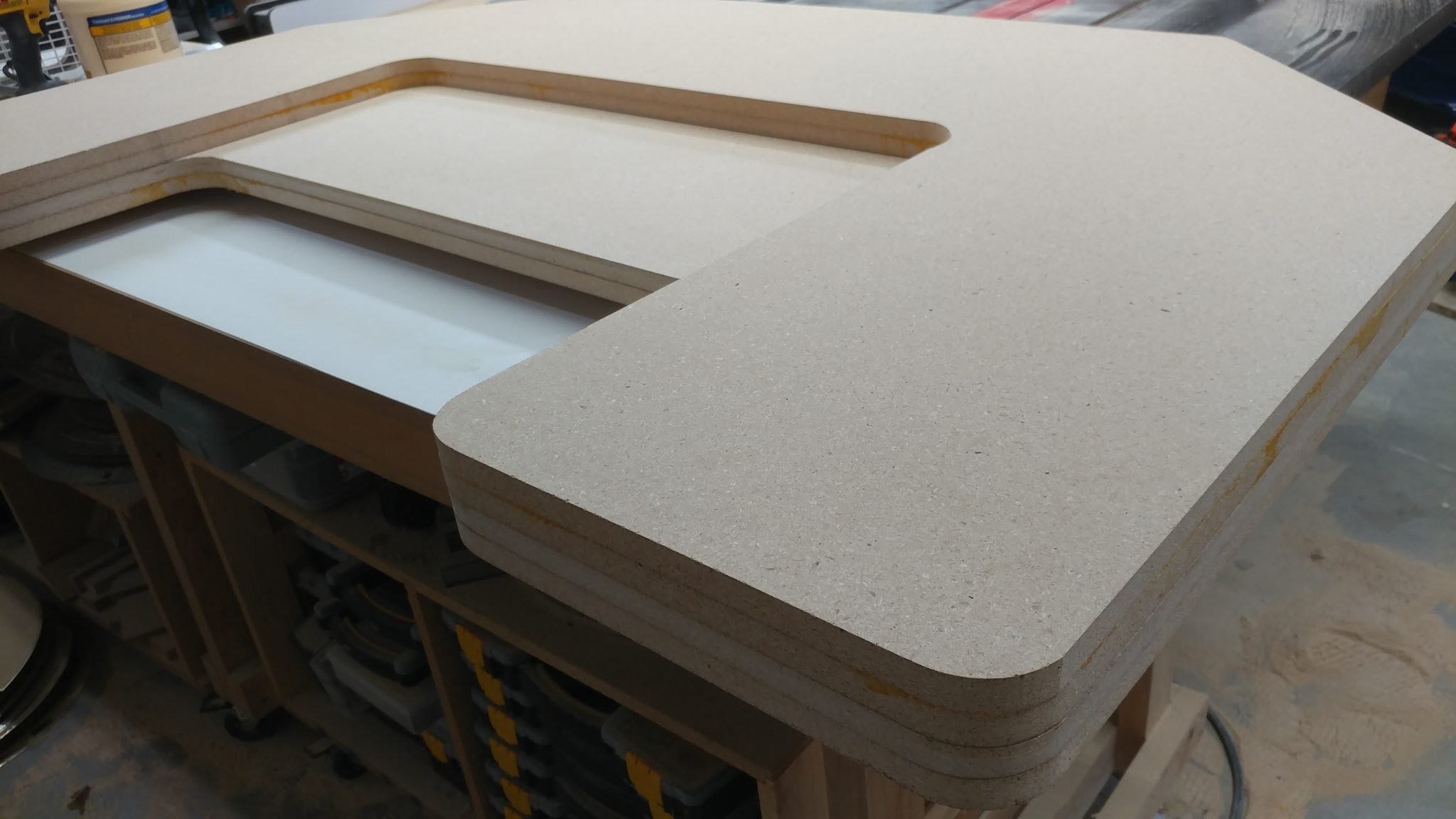
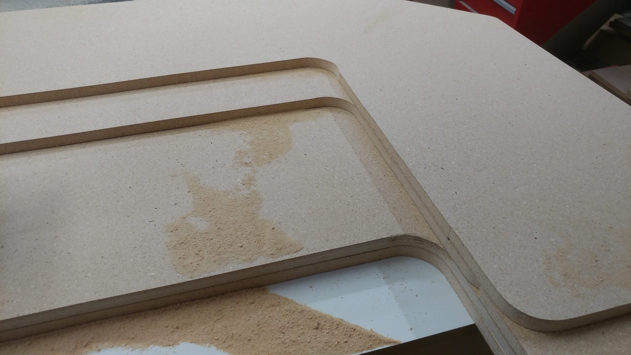
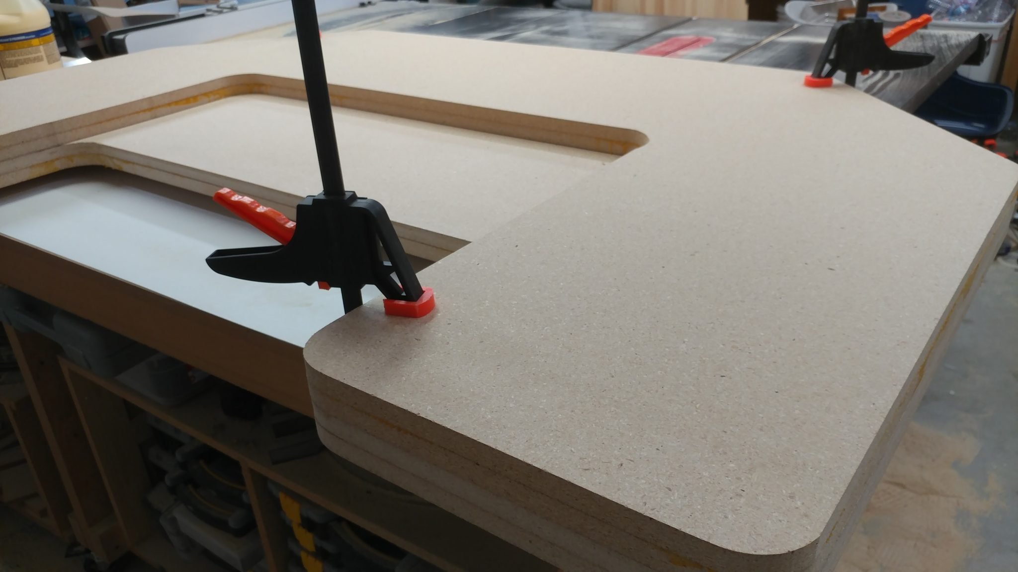
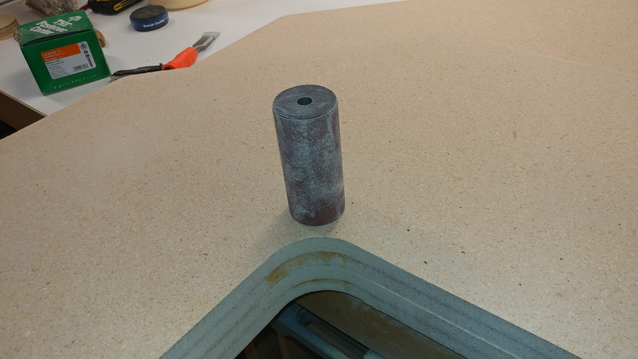
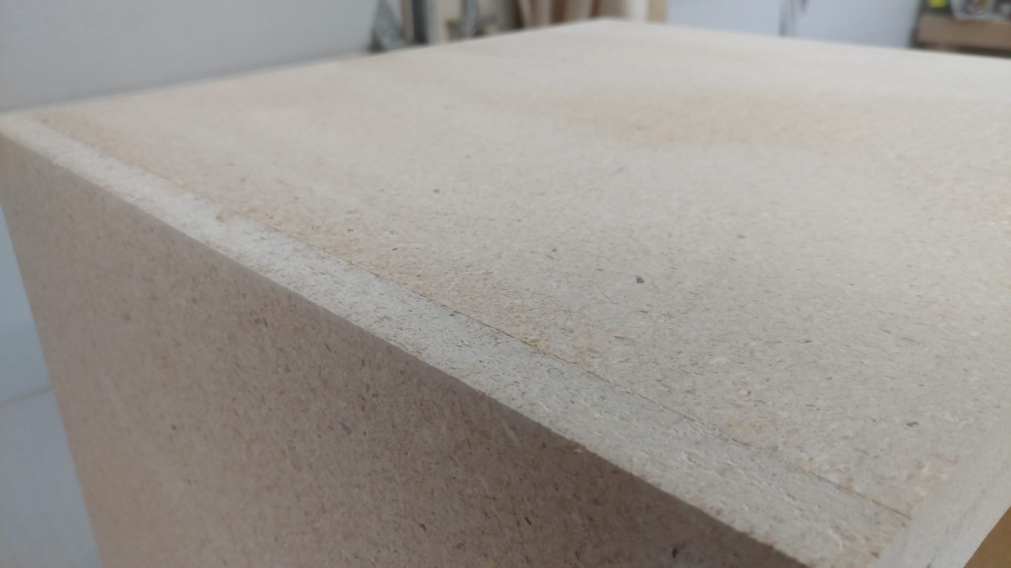
I spread wood filler into each seam and let it sit for an hour.


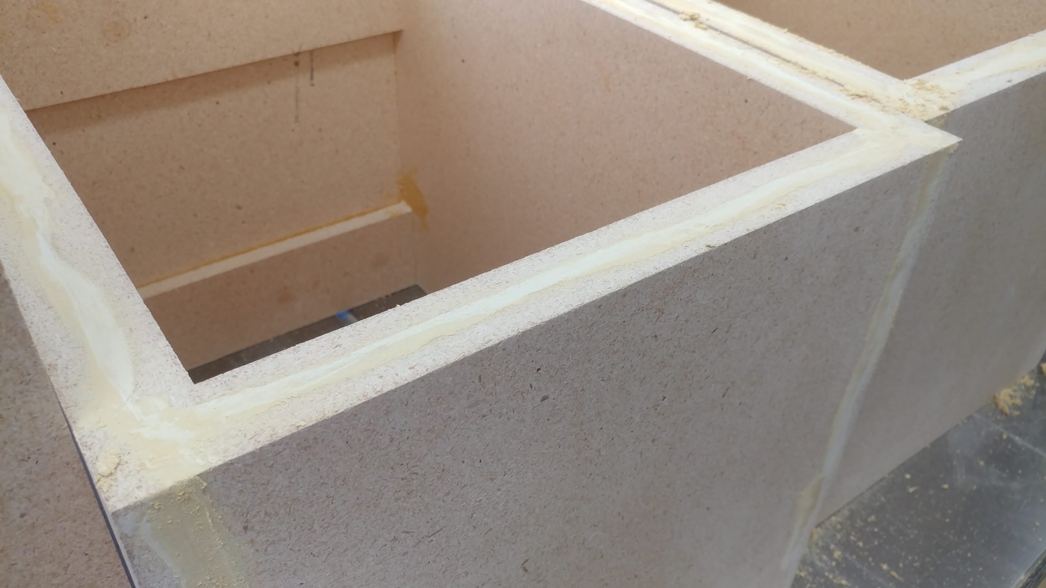
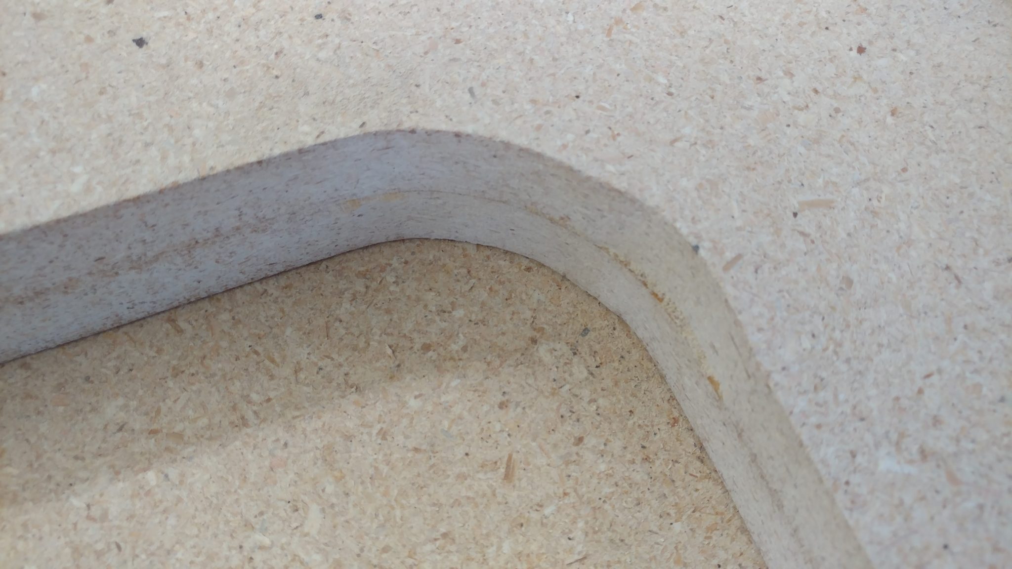
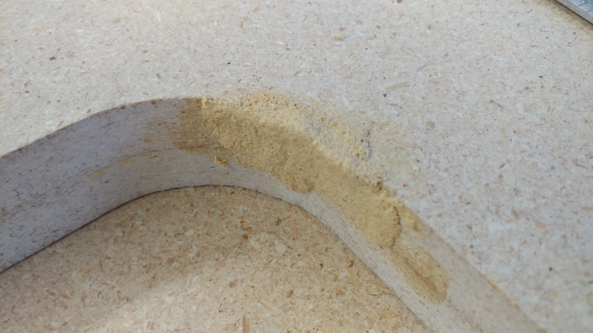
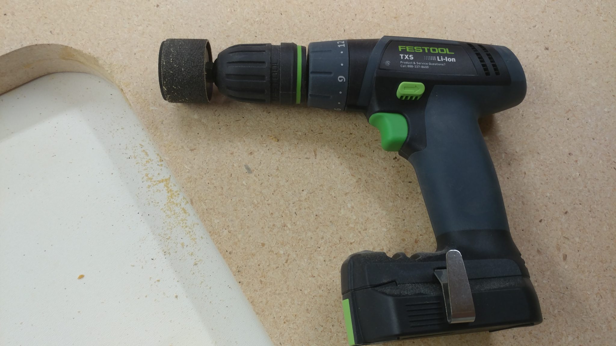
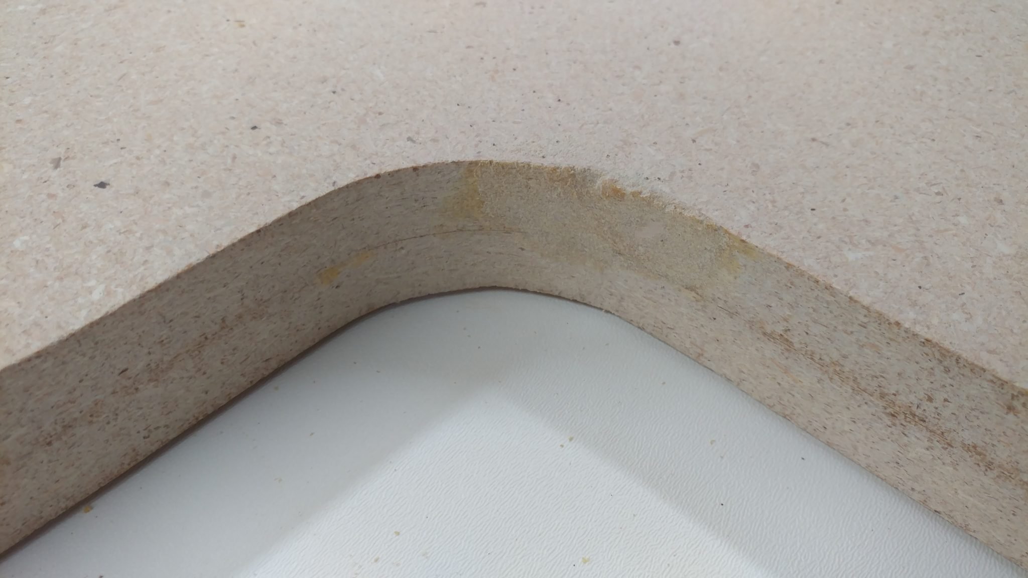
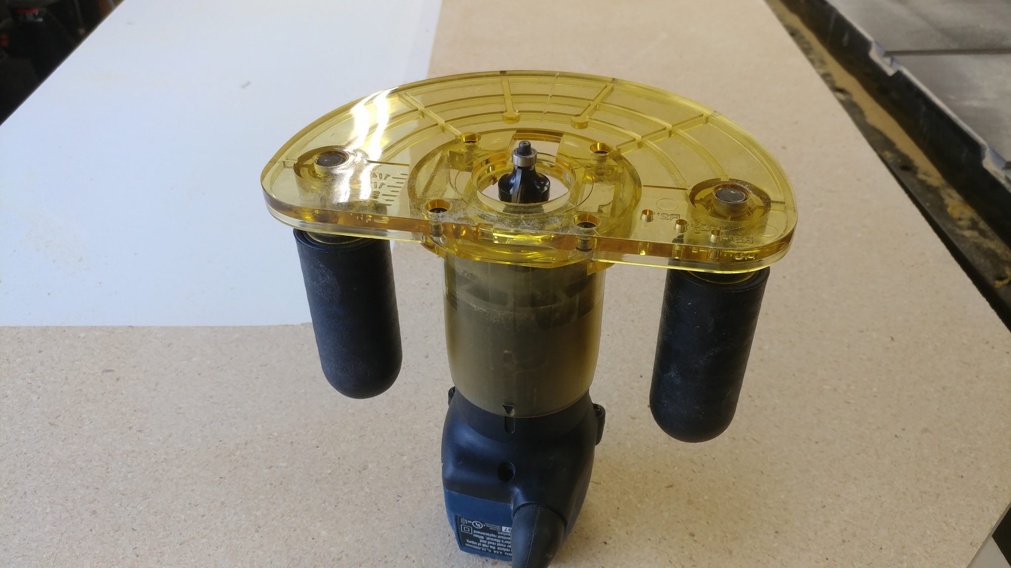
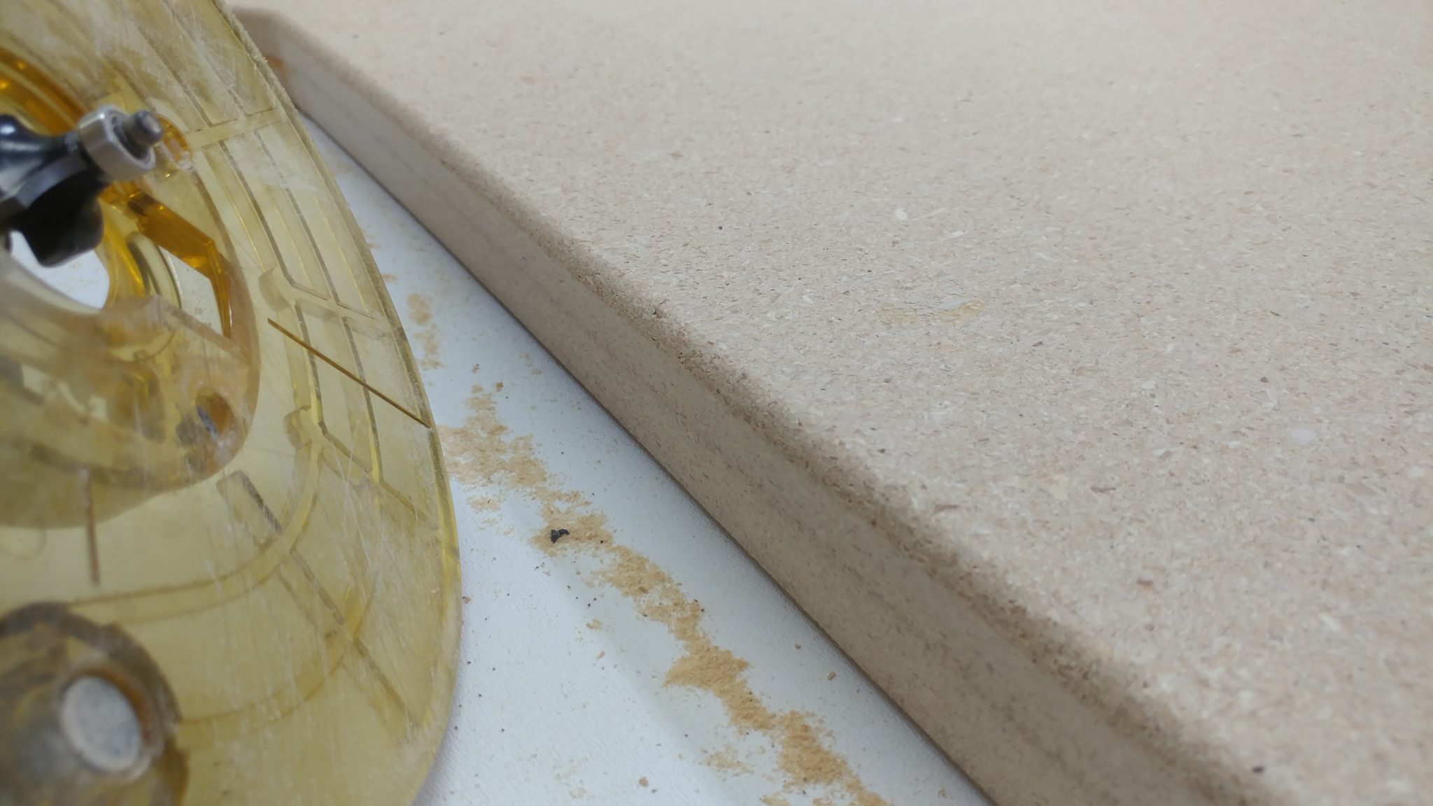
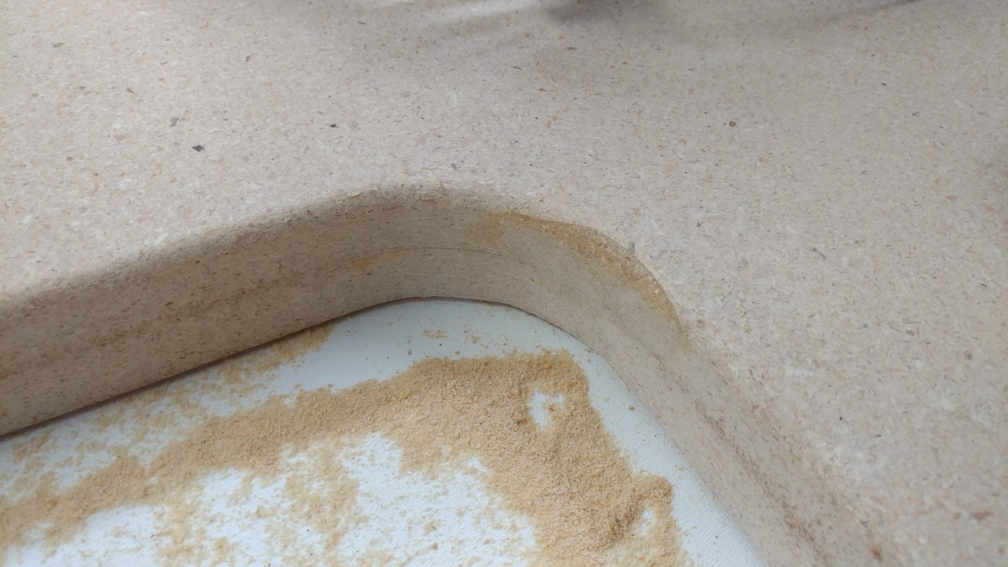
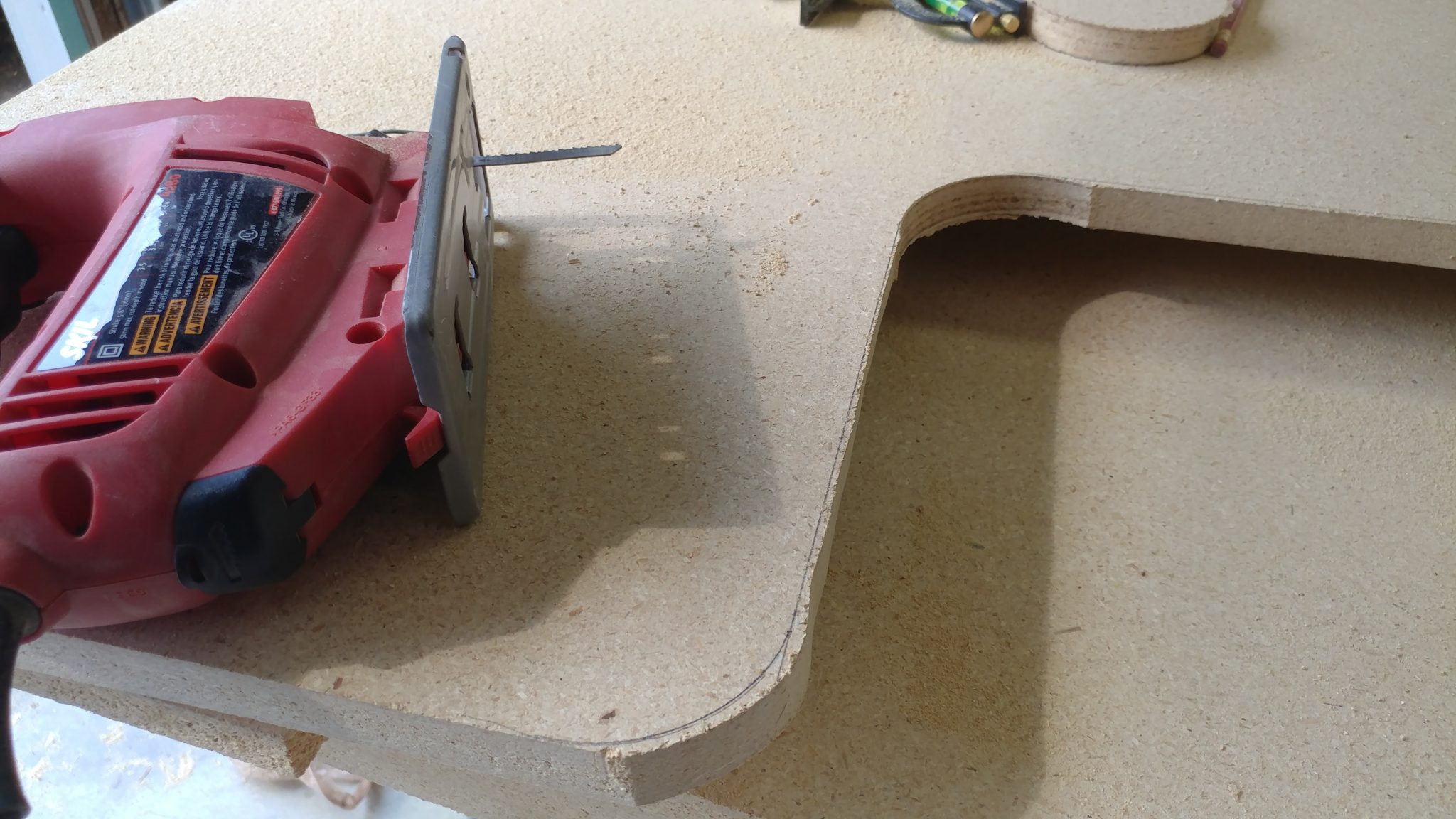
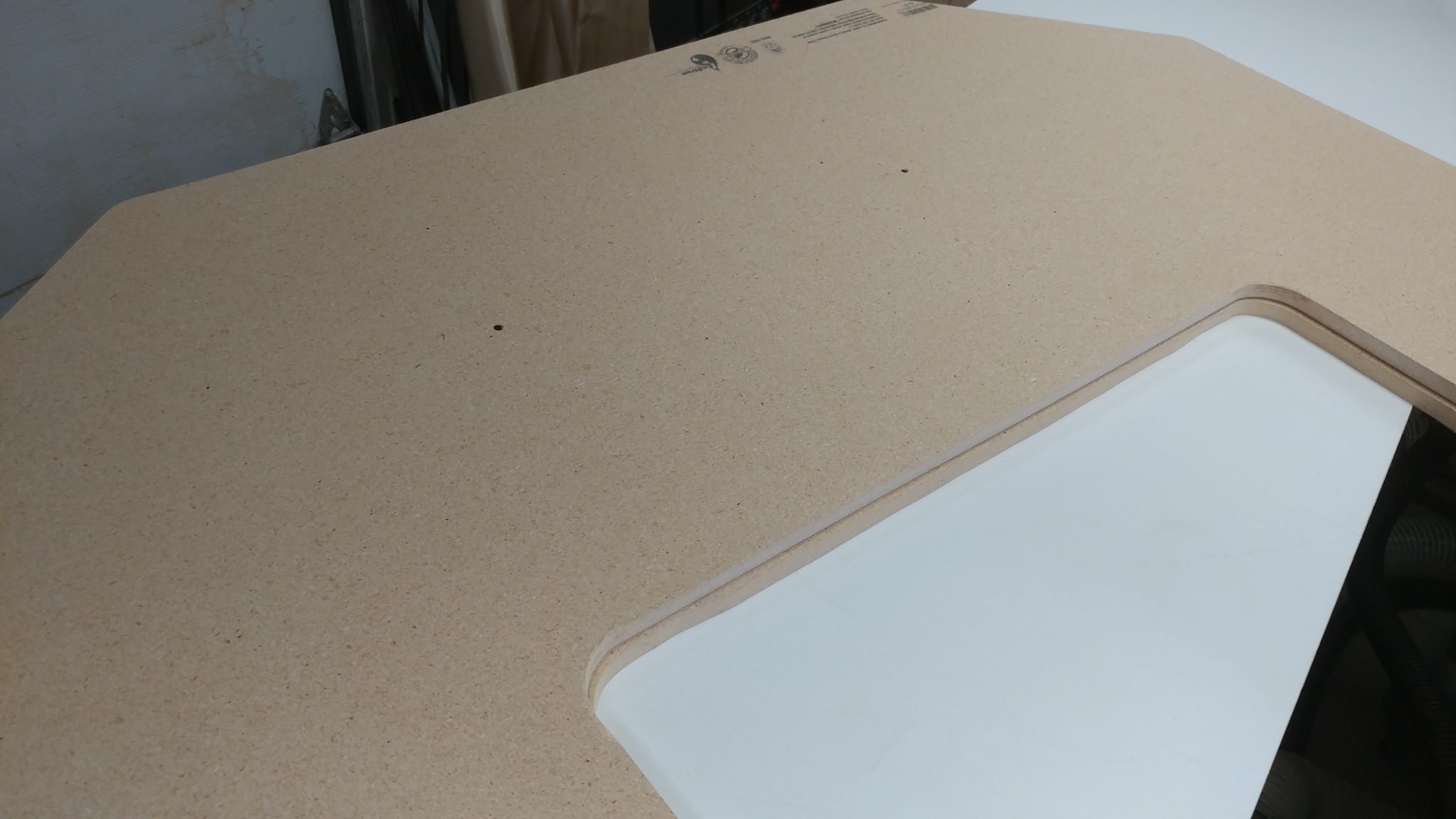
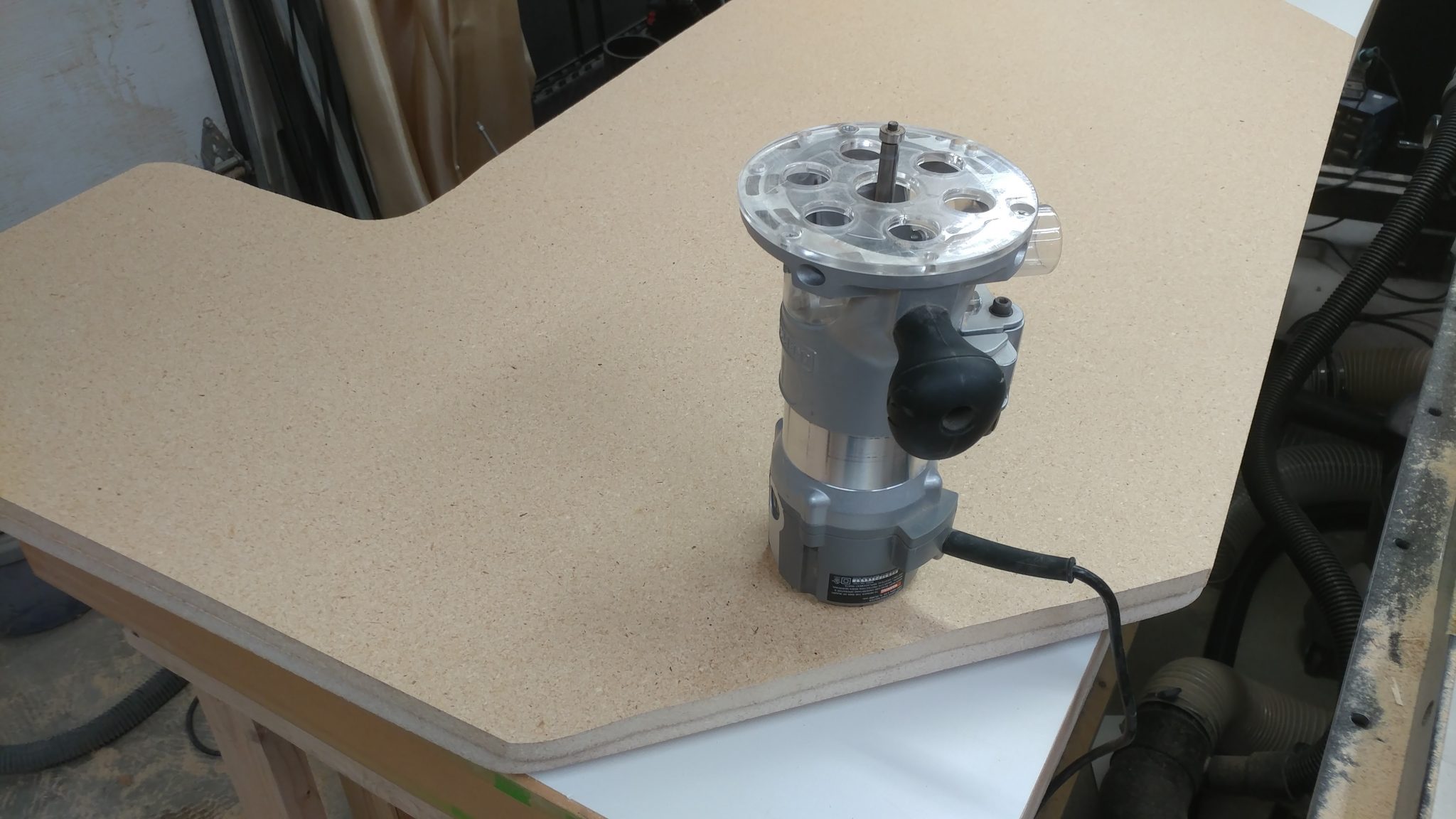
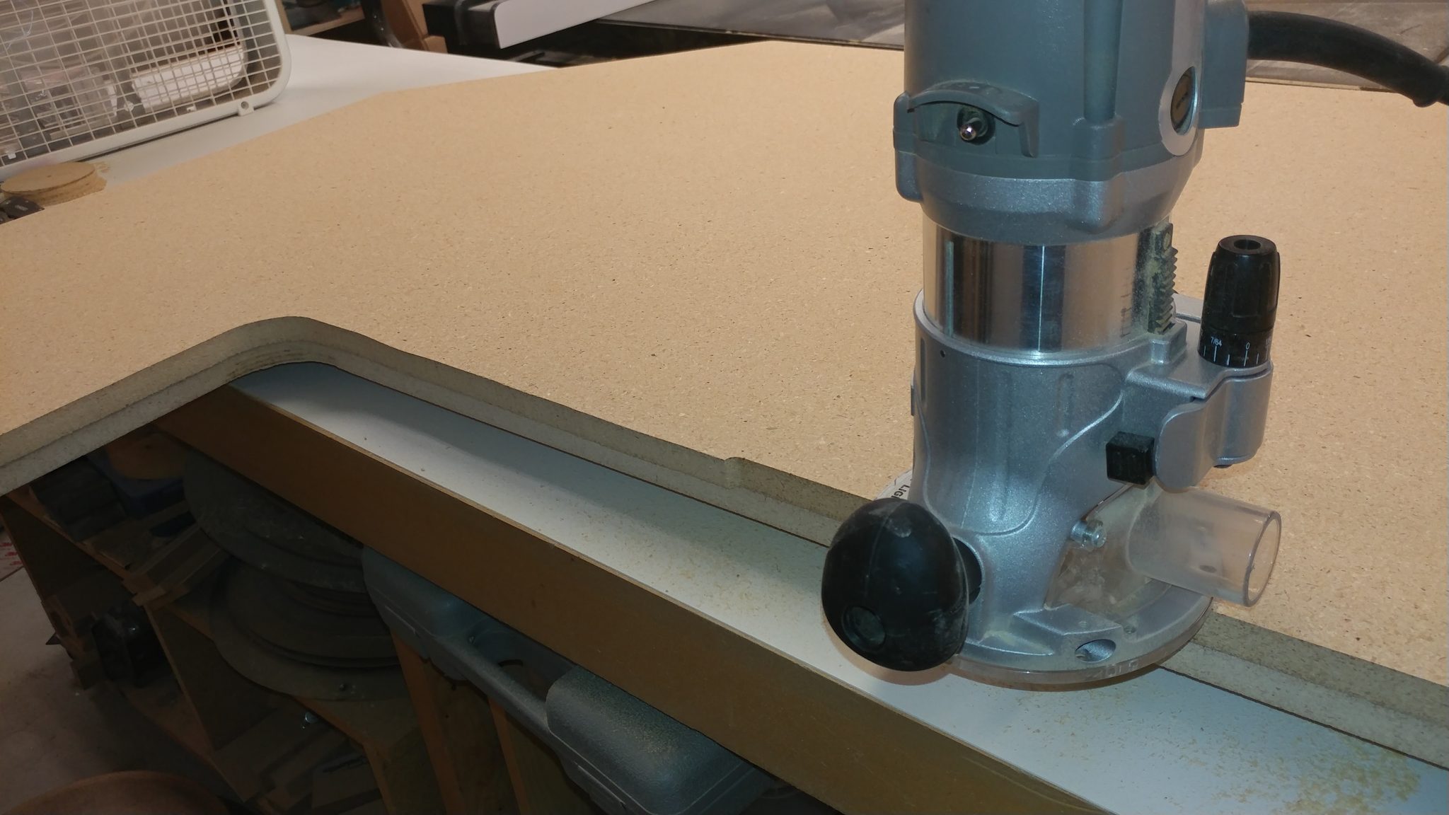
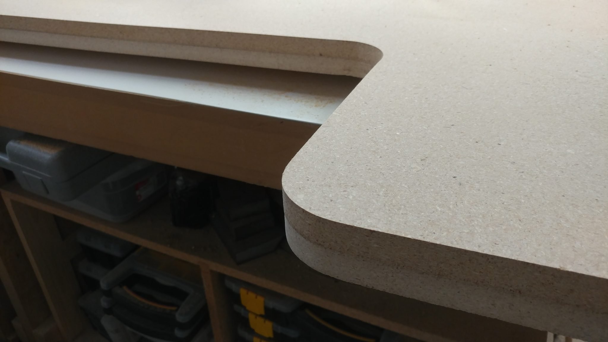
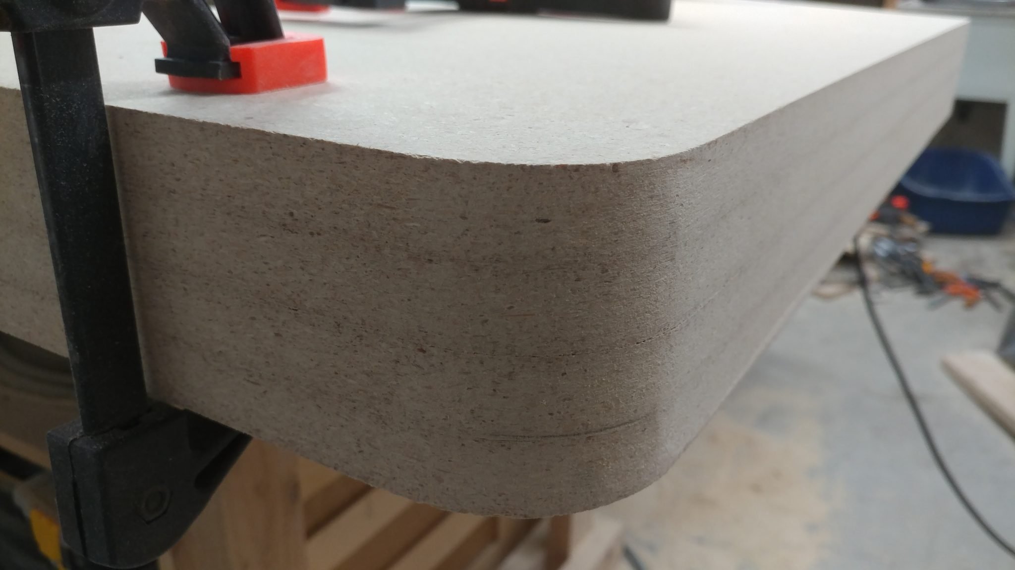
After letting it sit I cleaned up the edges with my random orbital sander then applied a 1/4″ roundover to each edge just like when I made the desk top and bottom.


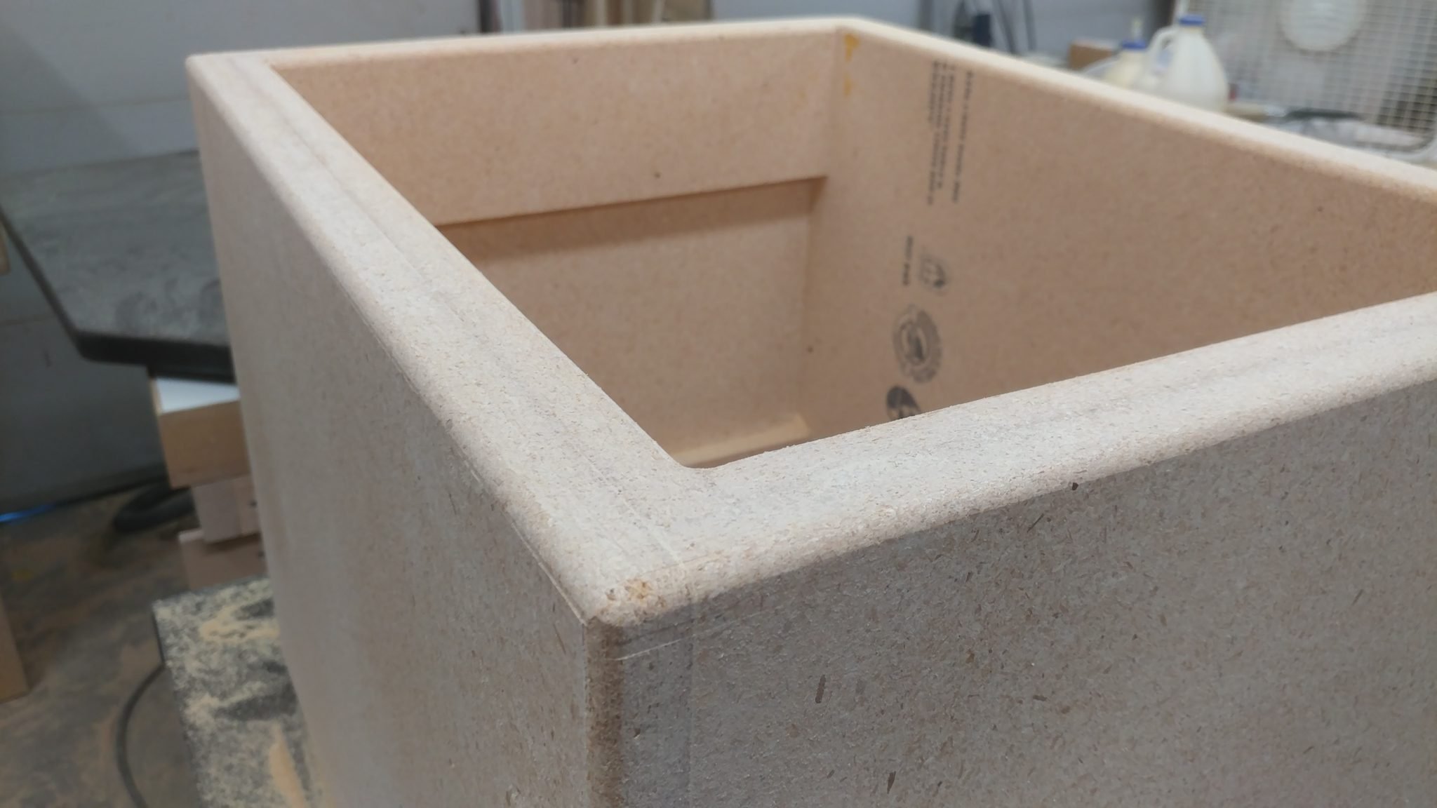
I cleaned up the routed edges with my random orbital sander again as well as with some careful hand sanding.


This concludes part 3.


Closing remarks

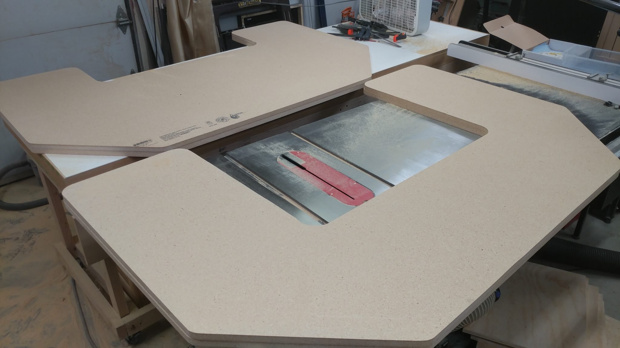
They’re all ready to be stained and finished.


As I said before, I don’t have a lot of room in my shop right now so it’s difficult to get this built but it’ll be worth it in the end.


If you have any suggestions, please leave them in the comments below.  I’d love to see any desk builds you’ve done.  Also, if you haven’t already, please consider signing up for my mailing list so you get e-mail notifications when I post new articles.


Studio Desk – Part 2: Final shaping of the top and bottom

The tops and bottoms are cut to size and glued up.  The next step is to fix a few mistakes and apply the roundovers so I can stain and finish them.


Fixing my mistakes

I make a lot of mistakes.  More than I would like.  I made a few while I was routing out the shapes of the desk bottom pieces.

First I slipped up when modifying the outline for the bottom of the desk.  I was able to correct this when cutting out the other half of the bottom but it left a nice gap that needs patching.


The second mistake was when I was cutting the aforementioned second half of the bottom.  As I was coming up on the area where I had made the mistake on the first half, I guess I was focusing on correcting for the first mistake and I ended up making another slight mistake.  You can see in the following photo that the inner corner is a little wonky.  I think the router, whose base is a little unstable, tipped a little and it caused this.


The following technique won’t always work, especially if you will be staining the piece but I’m going for a more utilitarian/industrial look so I actually welcome this.

Start with a blob of wood glue.  If you are wanting to stain this, I recommend trying stainable wood filler instead.


You’ll also need some sawdust, preferably from the same wood that you’re repairing.


Add the sawdust to the wood glue and mix it together.


This will take some trial and error in order to get something that works for you.  I was going for a dry yet pasty texture.


I rubbed a bit of wood glue on the spot that I needed to repair so the patch job can adhere to it better.


I then smushed (sorry for the technical term) a gob of the glue/sawdust paste into the repair spot, being sure to fill up all the space that needs to be filled.


When this dries, it’s going to be pretty hard.  I also need to flip this piece so I can repair the other spot.  To ensure that this wasn’t going to cause a problem, I waited till it had cured a bit then I took a utility knife blade and sliced off any of the filler that protruded from the top of the wood.


This left it flat enough to flip the piece without damaging the filler.


I did the same thing on the other mistake.


This one will be easier to hide since it is all on flat surfaces rather than an inner curve.


I let the filler fully cure for a day then I took my random orbital sander to it.  I placed a piece of blue painters tape next to the filler so you can see how it blends in.  It isn’t perfect but it’ll be good enough for this project.


The filler on the inner curve was a lot more difficult to deal with.


I ended up having to carefully use a drum sander attachment on my hand drill to get it smoothed out.


This one didn’t turn out as well but it’s good enough.  I’m putting a roundover on the edges so I’m not worried with how jagged it is.


Applying the roundovers

It was time to put the roundovers on the wood.  I decided to just use one of my little trim routers in an effort to avoid the mistakes that I just had to fix which were caused by the unsteady base on my larger router.  I outfitted it with a 1/4″ roundover bit.


I applied the 1/4″ roundover with the intention of then applying a 1/2″ then finally a 3/4″ roundover.  This is where I ran into a problem; I liked the look of the 1/4″.


I even liked how this looked in the corner where the patch job made an interesting little shape.


I really liked the look and feel of this roundover.


It looked especially nice when you backed off a bit and took the whole thing in.


I couldn’t make up my mind, and I only have one shot at this so I decided to ask for more opinions.  I took some scrap particleboard and did a mockup.  The left half is the 1/4″ roundover and the right half is a 1/2″ roundover.  I decided I didn’t want to do a full 3/4″ roundover.  I posted this photo along with a few others to several Facebook groups, Google+ groups, Instagram, and Twitter.  I wanted to see what others preferred.  Most feedback seemed to be favoring the 1/2″ but two opinions in particular stood out to me.  One was my wife, who said she preferred the 1/4″, especially since she sometimes attaches vices and jigs to the workbench that I made her and a big roundover would make that difficult.  The other was from Paul Jenkins (a.k.a. The Wood Knight).  He also favored the 1/4″.  In the end, I agreed with these two so I left it as 1/4″


The last step for this part of the project was to clean the pieces up to get them ready for finishing.  I sanded the top and bottom faces of each piece with a random orbital sander and 220-grit sanding discs.  The edges were cleaned up first with a coarse and then a fine-grit sanding sponge.


This concludes part 2.


Closing remarks

This is a difficult project, not in a woodworking sense since it’s ridiculously simple in it’s construction but in that I don’t have a lot of room in my shop at the moment.  My shop is currently difficult to walk in, much less build in.

I’m going to stain the wood next then apply several coats of matte finish polyurethane.  This isn’t going to be particularly interesting and will be time consuming so the next update might not have much to it.

Before I attach the legs and set up the desk, I need to also build the racks that will store the computer and recording gear.  These will determine the final placement of the legs since they are used to hold up the racks.  I’m going to try to get these built while I work on the finishing but I also want to make sure that the finish is protected from sawdust from building the racks and like I said, I have very little room in my shop right now.


If you have any suggestions, please leave them in the comments below.  I’d love to see any desk builds you’ve done.  Also, if you haven’t already, please consider signing up for my mailing list so you get e-mail notifications when I post new articles.


Studio Desk – Part 1: Preparing the top and bottom

I finally settled on a design for my studio desk.  It needed to fit into the breakfast nook, be mobile, and house the various racks of gear needed to record music.  I went through almost 20 designs before I settled on this one, not because it was the best, but because I knew I would never find the “perfect” design so I should just pick one and go with it.


The desk will mainly consist of a top and a bottom that are joined with vertical pipe sections.  The electronic gear will be stored in racks that will be modular, in that I can change their placement at a later date if I decide to.  I decided to use two layers of particle board for both the top and bottom.  It’s not apparent in the rendering but I’m also going to do a roundover on the tops and bottoms of each piece.  I’m also planning on staining the particleboard a dark color and protecting them with several layers of polyurethane.


Cutting the pieces to size

I started with the pieces cut slightly oversized on the panel saw.  Then I cut them to their exact length with a circular saw.  I did this by cutting a little bit off one side then flipping the board around and cutting it down to the exact length on the other side.  I did it this way so I wouldn’t have any factory edges on the final board, which may have nicks on them.


Next, I ripped them on the table saw to get them to their final width.  I did the same thing where I took a little off one edge then flipped it and ripped it to the final width.


Marking the outline

The next step was to mark out where I was going to cut.  Now, I should mention that although this desk has been planned out, some of it is dealt with on the fly.  I had some measurements but they were just guidelines.  The important thing is that it isn’t too wide to fit in the breakfast nook, or “control booth” as I’m now calling it.  That being said, the marks for cutting aren’t permanent so I drew them on painters tape at first.


Once it was decided where the cuts will be, I marked 2″ over in both directions from the inside corner so I could drill a 4″ hole.  This will be clear in a little bit.


I didn’t want my hole saw to wander so I grabbed a hammer and a punch and made an indentation where I wanted the hole to be centered.


Then I was able to use my (dull) 4″ hole saw to make this cut.


I wasn’t too concerned about blowout on the other end because of the roundover I plan on adding.  as such, the material wasn’t supported underneath.


I wanted similar radius’s on the outside corners, but they didn’t need to be exact.  I used the cutout from the hole I made to trace a corner radius on each of the outer corners.


I had the entire thing planned out and traced on the board.


Cutting out the first (and most important) piece

With the outline traced, I used a jigsaw to cut close to the line.


With the desktop shape cut out, I used a random orbital sander and a belt sander, both equipped with an 80-grit sanding disc and belt, to sand up to the line.


One layer of the desktop is complete.  I’m going to use this as a routing template for the other three pieces, with a slight modification for the two bottom pieces.


Using the first piece to cut out the second

To cut out the second piece of the top, I use the piece that I just shaped and trace an outline in pencil on the second piece.


Once again I use a jigsaw to cut out the shape just outside the line.


I attempted to secure the two pieces with some double-stick tape (which although it looks wimpy, has never let me down in the past).


After placing the second piece in place, I realized that the double-sided tape that had never let me down, was letting me down.  As a solution, I added two screws since this was going to be the underside of the desktop and wouldn’t be seen.


I equipped my router with a 1/2″ straight pattern bit.


I then routed out the second piece of the top.


An exact replica.


Cutting out the first bottom piece

This is where it got tricky.  The bottom needed to match the top but with the central area a bit deeper than on the two top pieces.  I accomplished this by tracing most of the outline then I pushed the top piece back a bit and traced the inner section.


Once again I cut it out with the jigsaw.


I then clamped the bottom piece to the top pieces, which were still screwed together.


I routed as much as I could.


I then moved the bottom piece a bit forward so I could route a bit more of the inner edges using the top pieces as a template.  To make sure I got it pretty even, I used a combination square to move each edge forward the same amount.


And this is where I screwed up.  I got a bit of the inner left edge routed fine then I went over to the right side.  Because of the placement of the router, I couldn’t see that I was coming up on the front corner of my template.  As a result, I took a chunk out of the bottom piece.  Fortunately, this will be easy to fix later since I’m using particleboard.  I’m just going to keep going and fix it later before I put the roundover on them.


After moving the bottom piece forward again I was able to get the inner corners to match those on the top pieces.


Cutting out the second bottom piece

I then traced the bottom piece onto the last piece of particleboard.


Then cut it out with the jigsaw.


Due to space limitations, I’m working with all the pieces stacked on top of each other.  Here, I’ve got all the pieces clamped together.  I’ll be using the bottom piece that I routed out (and screwed up) to route out the second bottom piece.


I managed to not screw this piece up in the same location.  Instead, I accidentally tipped the router as I was going around the inner corner.  Both bottom pieces will need some repair work before I do the roundovers.


All four pieces are cut to shape.  Time to glue them up.


Gluing the tops together

I apply a liberal coat of glue to one of the top pieces.


I then place the second top piece in place and clamp them together.  I’m using clamping cauls to help provide some firm pressure on the wider parts.


I let it sit overnight to cure.


After removing the clamps, the top is very sturdy.  I didn’t notice the two pieces coming apart anywhere when I removed the clamps.


Gluing the bottom pieces together

Now to do the same with the bottom pieces.


I glued this up in the morning then came back to it in the evening after performing at a show.


I don’t like to wipe the glue squeeze out when working with particleboard.  I’d rather let it cure in drips which can be easily removed with a chisel.


Final shaping

Both the top and the bottom are fully cured.  Now I’m going to do some final shaping and cleanup.


To ensure that both pieces are the same shape and have smooth edges I clamp them together so I can sand them smooth as if they were all one piece.


Here you can see that the edges are still a bit rough and there is still some glue squeeze-out to deal with.


After hitting them with my sanders, they are all much smoother and a uniform shape.


I had to get creative on the inside area.  This took a bit of moving and sanding, then moving again, and sanding some more.


Getting the inside corners was pretty tricky.  I used sanding sponges but that was taking a long time.  I then tried using the large spindle for my spindle sander and that worked a lot better.  I still have a lot of work to do on the inside corners but it’s getting there.


That’s it for part 1.


Closing remarks

I’m still working on the inside corners but I ran out of steam for the weekend.

The next steps are to put the roundovers on the edges and do some more sanding.  Then I’ll be staining them and adding several coats of polyurethane.

I haven’t decided on the size of the roundover I’m going to put on the edges.  My original intent was to put a 3/4″ roundover on both the top and bottom edge which would effectively make the edge a half-round.  I might try a 1/4″ or a 1/2″ to see how I like them.  It sounds like I need to do a mock-up on some scraps first…


If you have any suggestions, please leave them in the comments below.  I’d love to see any desk builds you’ve done.  Also, if you haven’t already, please consider signing up for my mailing list so you get e-mail notifications when I post new articles.


News – August 29th, 2017 – Recording and various other projects

A lot has happened in the past few weeks that has kept me from updating my blog.  I’ll try to summarize the important bits.


Recording for Bright & Shiny

I spent some time working on a few more tracks for Bright & Shiny as well as reworking a few older tracks that I wasn’t happy with.  I ended up re-recording a song that I was really struggling with since the timing is all over the map and I am playing along with pre-recorded tracks.  After recording the song sixteen times (no exaggeration) I finally came to the conclusion that I simply can’t release something to go along with this song that I would be proud of.  I spoke with the engineer and he said that they’re going to re-record the other parts with a click and get that to me so I can put down some decent drum tracks for it.


Slow-Motion video of new ride cymbal

I made a slow-motion video of my Sabian Vault ride cymbal that I featured a few weeks back.  This was mainly just a test to see what quality I can get out of my phone when filming at 120 frames-per-second.  Here’s the video that I shot:


Recording for The Map of Alice

I will be producing the recording of three tracks for The Map of Alice, the local gigging band that I play with each week.  I’ll be posting the progress here on this blog.  I will also be making a music video for at least one of the songs, possibly all of them.


Web site creation for The Map of Alice

The time that I haven’t been spending in the studio, playing live, or watching Twin Peaks, I have been spending on the new web site for The Map of Alice.  I’ll announce when it has gone live.


Studio desk plans

I’ve once again changed the plans for my studio desk.  My problem is that I only want to do this once so I’m being rather picky about how I put this together.  I don’t have anything finalized yet but I’m getting close.


Shop issues

Work in the shop has been minimal, at best.  I can’t even walk out there right now.  My main problem is that I have too much building material.  I’ve got piles of scrap lumber, cracked cymbals, metal stock, electrical components, and aquariums.  Yeah, that’s right.  There’s a big 55-gallon aquarium taking up a big chunk of space in my shop.  The kicker is that it isn’t even mine.  Now that the busy August month is pretty much over and the weather is (hopefully) going to start cooling off pretty soon, I’ll be able to focus on getting my shop into a usable state again and start cranking out some more build projects.


My daughter turned 18!

This actually took up a good chunk of my time.  My daughter, Audrey, turned 18.  We had a few get-togethers but mostly we’ve been trying to help her make the transition into adulthood.


That’s it.  I’m sure I’ve forgotten a few things but the point is, I’ve been busy.

News – August 2nd, 2017 – Apprehension Engine Electronics Prototype

I started putting together the electrical prototype for my version of the Apprehension Engine.  You can read about my plans for this project here.

This version is going to have two channels, each with its own reverb tank which will result in each channel having its own sound.  I started by gathering the necessary parts.  Here’s what I’m using:

RCA jacks

1/4″ Mono audio jacks

5.5 mm X 2.1 mm power jacks  (X2)

27 mm piezos

Reverb tank: Long decay

Reverb tank: Medium decay

Input amplifier

Output amplifier

Power supply: 12 VDC 2 Amp

Power supply: 5 VDC 2 Milliamp


The output amplifier has an volume potentiometer.  I want to have access to this while using the instrument but you’ll notice that there is also an 1/8″ jack right next to it on the board.  This is the input.  Unfortunately, I don’t want this sticking out the front of the instrument so I decided to remove the potentiometer so I can attach it with wires and locate the actual volume knob away from the board.


Looking at the underside of the board you’ll see that it should be easy to de-solder and remove the potentiometer.


The potentiometer has been successfully removed.


I’m temporarily securing the board to a surface by using screws and standoffs.


One of my favorite tricks when prototyping electronics is to use those $1.00 storage bins.  At first I decided to attach everything to the top of the lid.  I changed my mind later, which you’ll see.


I attached the standoffs to the board and used that to mark where I needed to drill holes in the lid for the board.


I drilled the holes then inserted the legs of the standoffs then secured them with nuts.


The input amplifier is a bit different.  It’s pretty small and doesn’t have holes for standoffs.  I also don’t necessarily need to access the potentiometer on this board as I expect to set-it-and-forget-it.


Looking at the underside shows a spot where there aren’t any traces so I decided to secure this board with sticky-backed velcro.


Both boards are secure and ready for some prototyping.


The board requires the installation of header pins.


Easy enough.


To attach the potentiometer to the output board, I attached some female headers to the board.  I started with some 5 pin sections.  I only need three of them but they’re double-spaced so I need to start with 5 and pull out the 2nd and 4th pin with needle-nosed pliers.


This results in 3-pin headers that I can solder to the board.


To hold the headers in place, I inserted the pins for the potentiometer in the headers and then I held the potentiometer to the board with some electrical tape just long enough to secure one of the pins.


After the pin was secure, I removed the tape….


…and soldered the remaining pins.


To make the plug that will insert into the headers, I started with a length of header pins.  Using a pair of snips, I made two five-pin sections.


I removed the 2nd and 4th pins just like I did on the female headers.


I made a cable out of 22 awg wire.  I normally try to do some sort of color scheme that makes sense so I decided to have the left most pin on each row connect to a green wire, and the other two pins to both connect to either a read or a black wire.  I started by cutting some lengths of wire.  Then I stripped the ends.


I soldered the wires to the pins.


Then I covered the bare connectors with heat-shrink tubing.


Both cables are attached.


Anyone who’s made their own instrument or mic cables can relate to this: always remember to put any sleeves on the wires BEFORE soldering the other ends on.


I soldered the wires to the potentiometer then applied the heat-shrink tubing.


Now I’ve got a volume knob that I can attach away from the board.  This may not work, however, as I explain later.


Each board will use its own power supply.  The output amp needs 12 VDC at 2 Amps while the input amp only needs 5 VDC ad 500 Milliamp.  I tried to find an easy way to get different connectors so I don’t accidentally connect the 12 VDC supply in the input amp and damage it, but it’s pretty hard to get the correct power supplies with the connectors that I wanted.  Until I come up with a better solution, this will have to do.


I soldered wires and applied heat-shrink tubing.


The wires for connecting the power jack to the output amplifier are pretty simple to attach.


To connect the power jack to the input amp board, I need to add a 2-pin connector.


The power cable connects to the two pins on the board.  I plugged in the power adapter but there isn’t an indicator on the input amp so I don’t know yet if I wired everything up correctly.


I plugged the power adapter in to the output amp and it all seems to be working.


Now it’s time to get some signals into and out of the prototype.  I’m hooking up four 1/4″ TS jacks, two for input and two for output.


I tinned the tabs on the 1/4″ jacks then attached both wires.


They each connect easily to the output amp.


To get the signal into the output amp, I am using an RCA to 1/8″ stereo adapter plugged into the input jack on the board.


I also found an older knob that I attached to the potentiometer which I thought looked a little better than the one I was using.


The signal both going out of the input amp and into the output amp will require RCA jacks.  I have a pair for each board.


I soldered the wires to the tabs on each jack.


I made four of these, with two of them having plugs for connecting to the header pins on the input amp.


The input amp now has power and a way to send a signal out to the reverb tanks.  Now I need to get a signal into it.


The input amp accepts a stereo signal but both channels share a common ground so I shortened the ground wire on one of the 1/4″ TS jacks so I could attach it to the ground tab on the other jack…


…which I did.


I then attached a three-hole plug to attach the input connectors to the input amp.


The input amp is now all wired up.


I am using two different reverb tanks.  According to their spec sheets, the shorter one actually has a longer decay than the longer one.  They both take a single audio signal in through an RCA jack and spit it out the other end through another RCA jack.


I used a standard stereo RCA cable to connect to the output jacks from the input amp.  I then connected each end to a separate reverb tank.


I then used another stereo RCA cable to connect the output from the reverb tanks to the input jacks of the output amp.


I then turned everything on and tested it out.


The good news is that it works and nothing exploded.  The bad news is that when I attached the wires from the output amp to the volume potentiometer, I basically made a little radio.  When the volume is maxed out, it has a pretty loud buzz.  As soon as I lower the volume, it starts to pick up radio stations.


I tried hooking up another identical amp but without the potentiometer removed and it sounds great.  I tried adding ferrites to the wires to see if that would help but it doesn’t.  I’m going to have to try something else.


To make it easier to test with, I relocated everything to the inside of another storage bin.

News – July 24th, 2017 – New Sabian Ride

This weekend I added a new cymbal to my setup.  It’s a Sabian Vault Custom Shop HH 22″ ride with a semi-lathed pattern on the top and a completely lathed underside.


I used it at our regular Sunday gig at McNallly’s Taproom (we play each Sunday from 3:00 – 5:00).  The band plays Gypsy Jazz so it was a good venue to try out this cymbal.  I added a Pro-Mark Sizzler to it to see how it would work and it performed admirably.  I typically use a 20″ Sabian Ed Thigpen Crystal Ride with the sizzler but this 22″ cymbal is my new favorite.  Tapping it with my brushes caused it to sizzle for quite a while and it didn’t get the annoying vibrato sizzle towards the end that other, thicker cymbals get.  It complimented the cut-down Wuhan cymbals well, although it made my LP Granite Blocks rather hard to reach.

The lathing and hand hammering make for a beautiful cymbal, but also of note is the pronounced bell.  I haven’t had a chance to use this at higher volumes yet but some preliminary tests show that the cymbal crashes well, and even though I’m not one who crashes their ride cymbals, I ended up crashing on it several times and I loved the sound.


I’ll post some video of the cymbal soon.  It’s got a nice satisfying wobble to it when you hit it and a nice, dry, smoky sound.


News – July 20th, 2017 – Studio Desk Plans

I think I may have settled on a final design for a recording studio desk.

This satisfies all of my requirements.

  1. It’s mobile.
  2. It doesn’t take up much space.
  3. It is self contained.
  4. It has amenities for both the studio engineer and the talent.


The plan is that it will be a desk that has all of the electrical and audio connections built in.  If you need to plug in an amp, the desk will have several electrical jacks.  Need to charge your phone while you record?  There are charging jacks for that as well.

There will be connections for power from the wall and ethernet into the desk, as well as a 5-port hub with ethernet jacks on both the front and back of the desk.


The construction of this might take some time since I haven’t decided if I want to make it out of cheaper plywood and cover it with laminate, or make it out of nicer wood and just stain it and add a few clear-coats.

What do you think?  Any suggestions?  What am I missing?

News – July 18th, 2017 – Apprehension Engine Build

Several months back I discovered a musical device called The Apprehension Engine.  It was created by Tony Duggin-Smith for Mark Korven who is a film composer who was looking for some new sounds to use when creating horror film scores.

I’ve knocked around the idea for a while and I’ve decided to build my own.  I have experience creating soundmakers of this type, and I also have experience wiring up electronics in instruments, but I’ve never combined the two to create something like this.

My approach is going to be slightly different, however.  I’m going to be outputting a stereo signal, with each signal bus going through its own reverb tank, each with a slightly different decay time.  I’m also going to be implementing several other noisemakers that I have worked with in the past.

I’ll be posting detailed project updates as it progresses and a complete walkthrough when it is complete.

Check out the link below for more information.

Sounds of the Nightmare Machine

Horror Musical Instrument – The Apprehension Engine


News – July 1st, 2017 – New studio lighting

I’ve spent the last few days installing some new lighting in my recording and rehearsal studio.  I have track lighting running down two of the walls but there weren’t any lights behind the drumset.  I added 5 track lights above and behind the kit and they are set up so I can turn them on independently of the other lights.  


This required some careful and confusing wiring.  I tapped into one of the electrical outlets and ran a wire up to the lights.  Unfortunately, this outlet was previously wired up pretty strangely, as you can see below.


This room was originally set up with a light switch controlling the upper plug in each outlet.  I changed it a while back so both plugs will be always on and the light switch would instead turn on the track lights on the north and south walls.  This particular outlet had 4 separate lines coming in, two were 3-conductor cord and two were 4-conductor.  This means that this outlet box had 14 individual wires for me to deal with.  It took a lot of trial and error but I figured out the wiring logic of our house’s previous owner and also figured out what I was thinking when I changed the outlets a while back.


I put red and blue lights in the cans and it adds a bit of a “live performance” feel to the kit.


Here you can see the lights.  You’ll notice right below the track is a light switch.  The wires come from the outlet below up to this switch then off to the lights.  I’ve decided that I’m going to change this a bit.  I’m going to install a 3-gang box and change the single switch to a double switch.  I’ll then put two outlets in the other 2 spots in the box.  One of the switches will turn on the lights and one of the outlets.  The other one will turn on the second outlet.  I’ll post an update when that is complete.


Is this something that I should do a write-up about?  Would this help you in your own projects?  Let me know by leaving a comment below and feel free to sign up for my mailing list so you will be notified when I post future articles and news updates.


UPDATE: July 2nd, 2017

I changed the single switch to a 3-gang box with a double switch and two standard plug outlets.  The top switch sends power to the lights and the middle outlet.  The bottom switch sends power to the right outlet.  I’m planning on plugging a fan into the right outlet and maybe some other lights into the center outlet.

News – June 15th, 2017 – Performance video update

The recording for the upcoming album by Bright & Shiny is progressing well.  I have been playing around with the video for a few songs and although it isn’t finished, I decided to share an early version of one of the videos.

I’m playing around with the title sequence and cutting back and forth between different camera angles.  Although the drum performance is pretty much finalized, the rest of the song is not the finished version.  Also, none of this has been mixed and mastered.

A few interesting things to note with this song is the use of some of my “Rescued Cymbals”.  In addition to the small chime cymbals that I use in pretty much every song, I am also using two cut down Wuhan Lion (or China) cymbals which are positioned above my two main rack toms.  I’m also using a 12″ Glennie’s Garbage positioned above my hi-hat.  This is quickly becoming one of my favorite cymbals.

Enjoy…