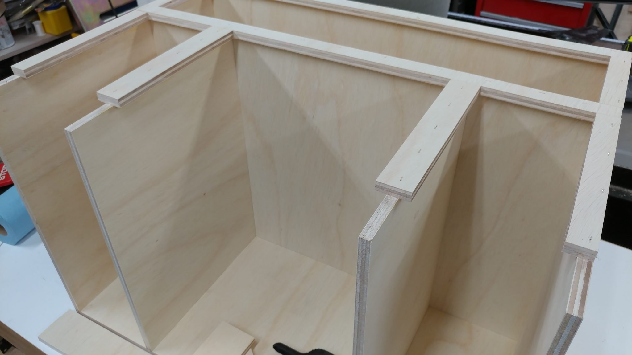

This is a continuation of Table Saw Modification – Router Table Enclosure: Part 1 – Carcase.
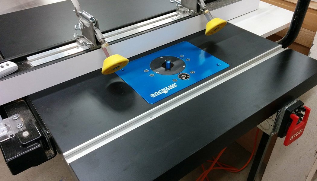
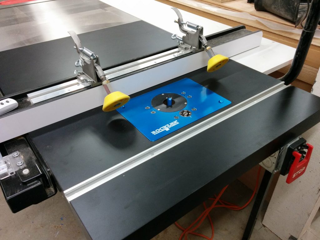
A while back I converted my side extension table into a router table. Although not strictly necessary, I am going to enclose the router and add dust collection, while also creating much-needed storage and enclosing the electrical.
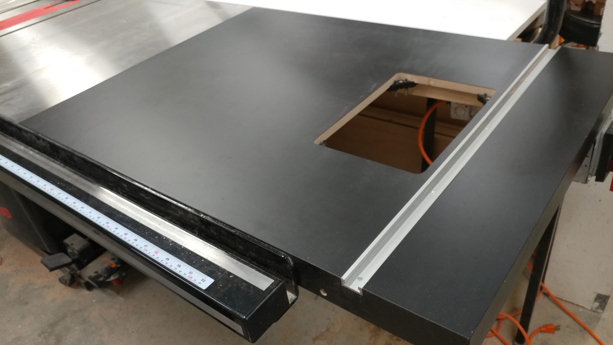
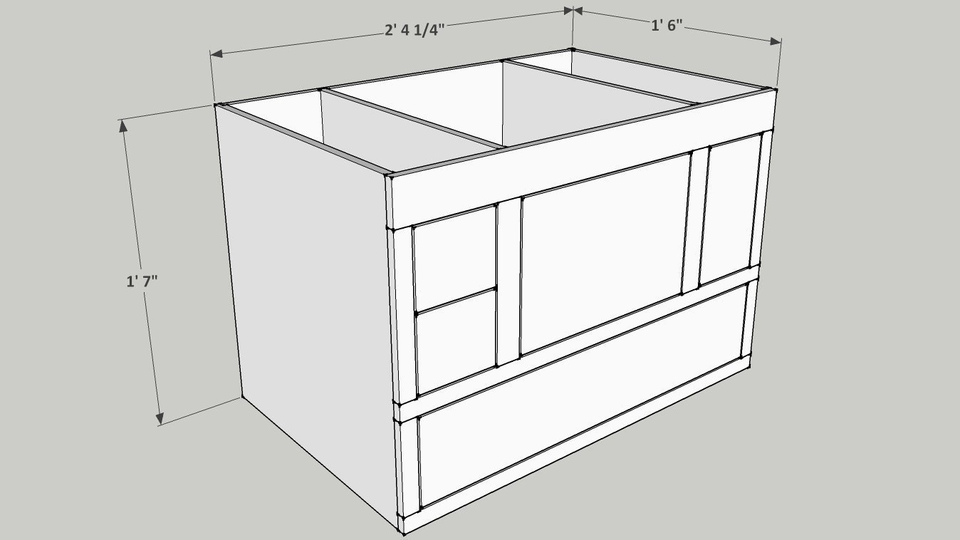
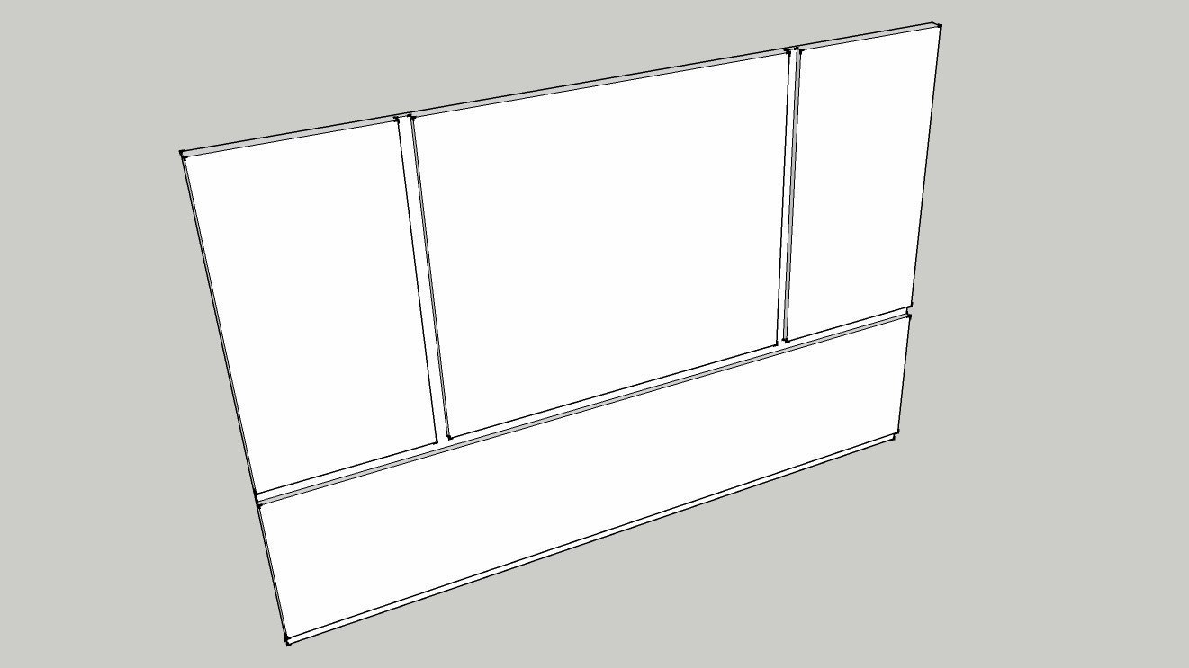
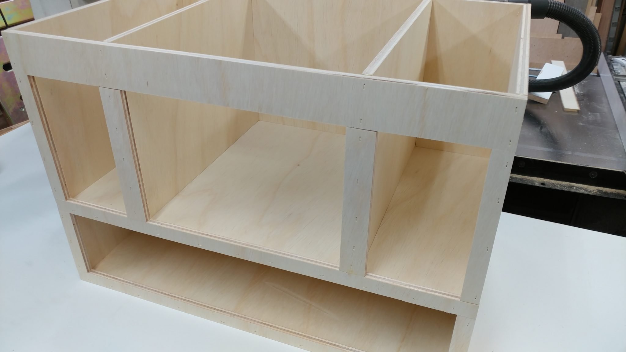
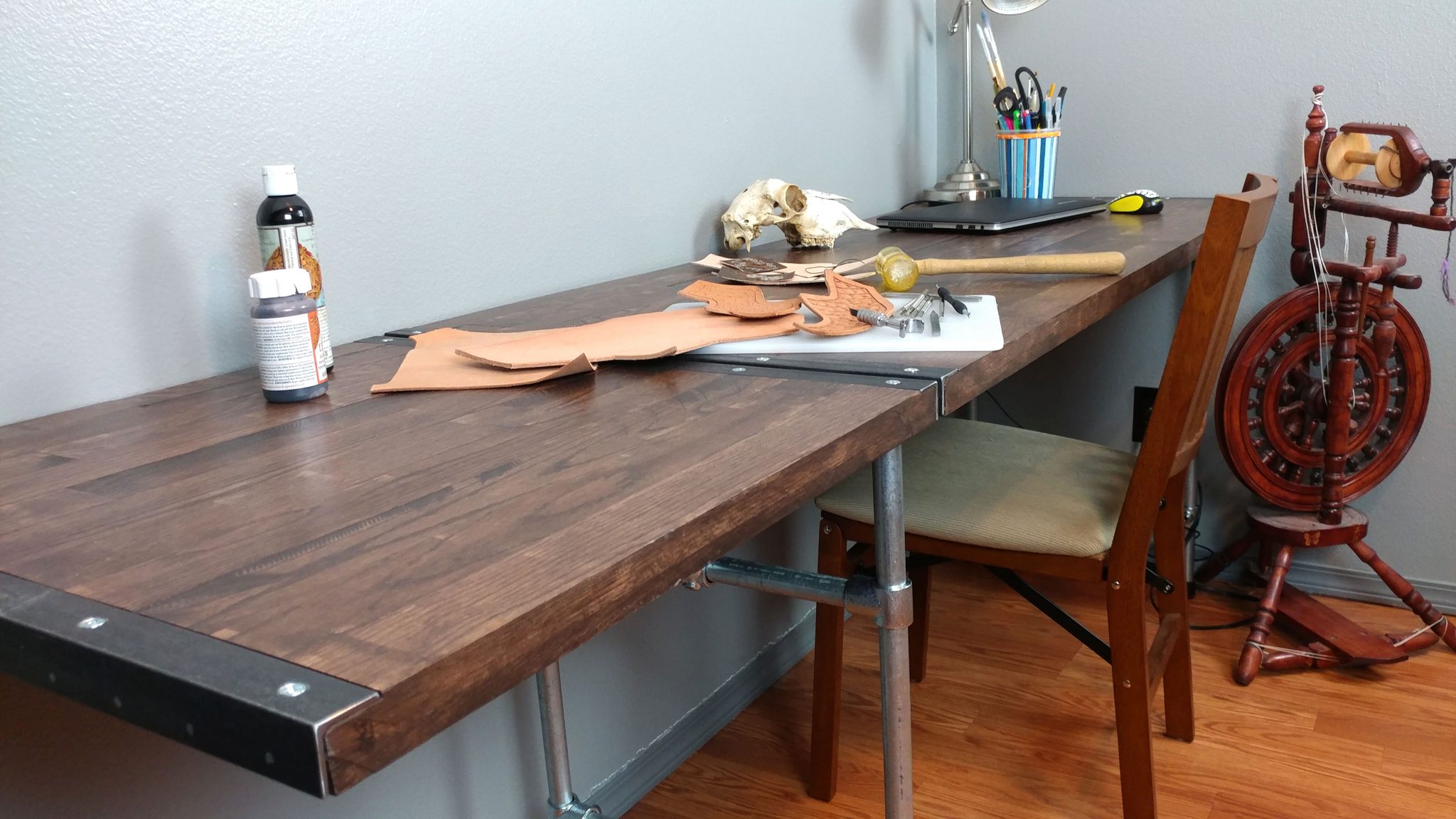
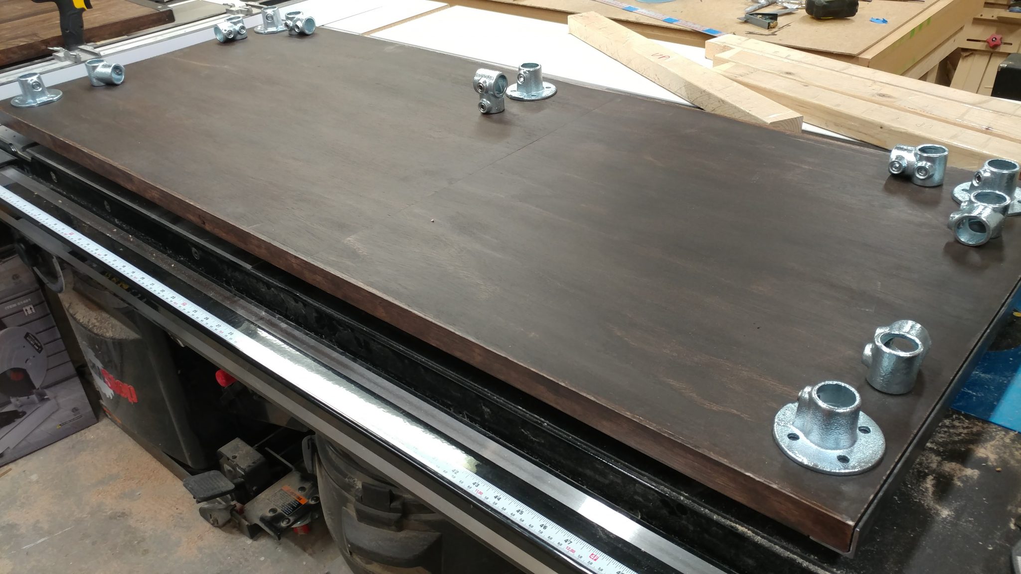
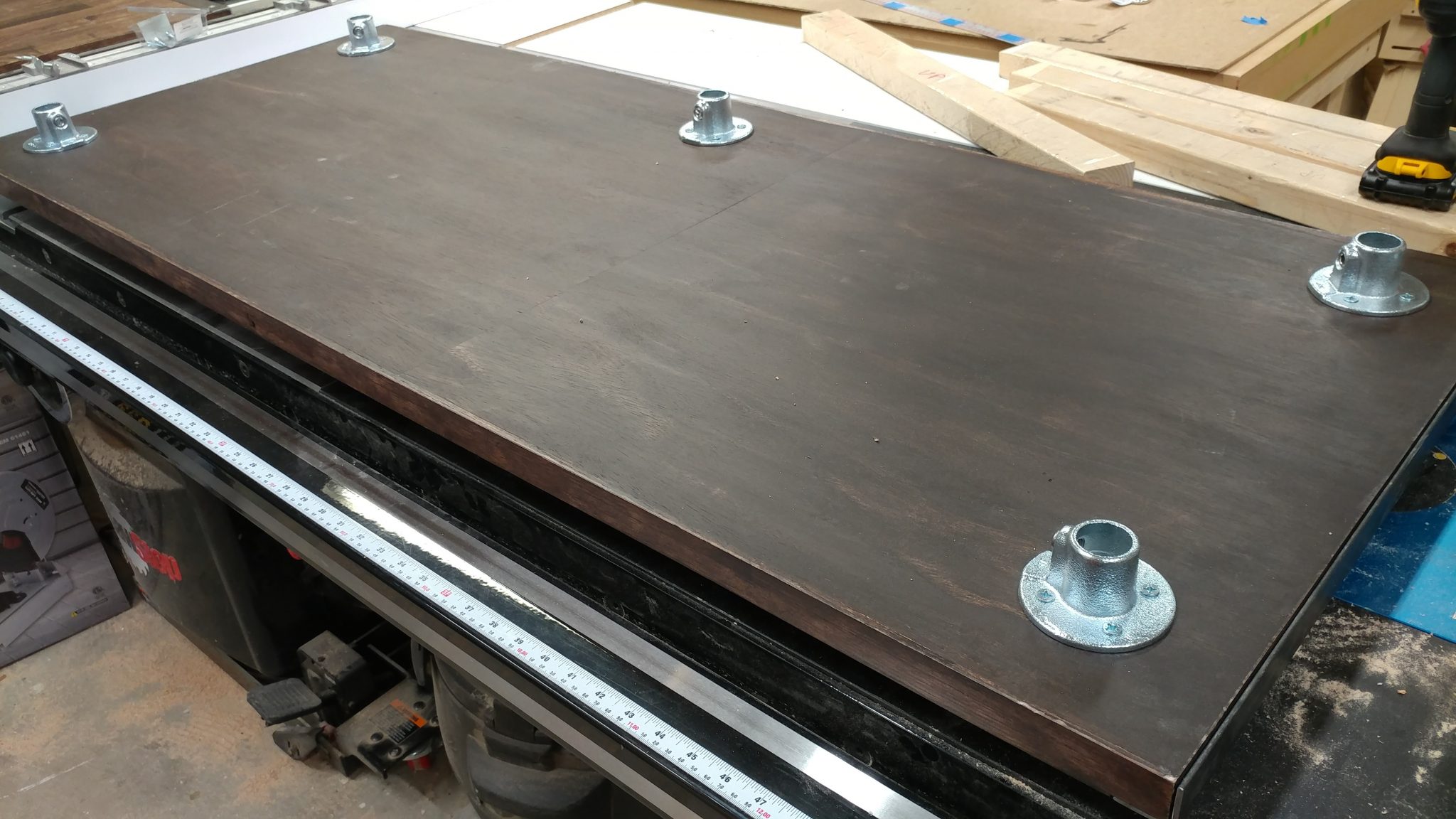
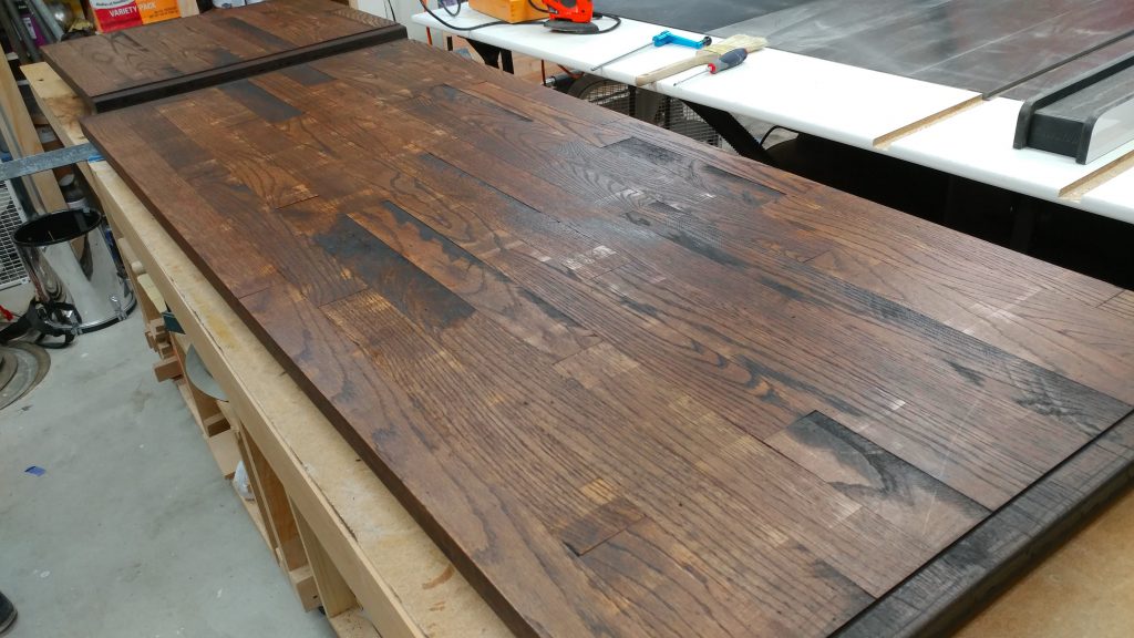
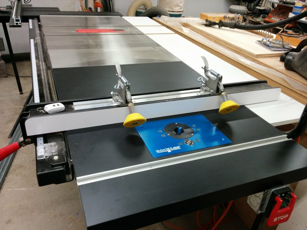
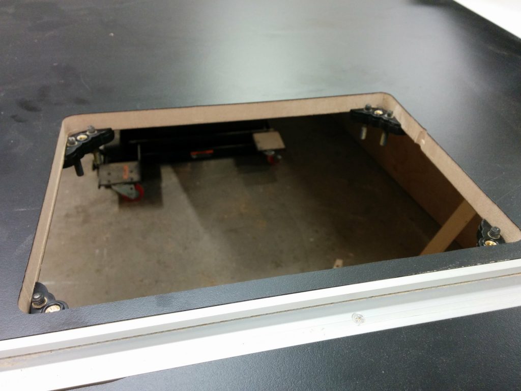
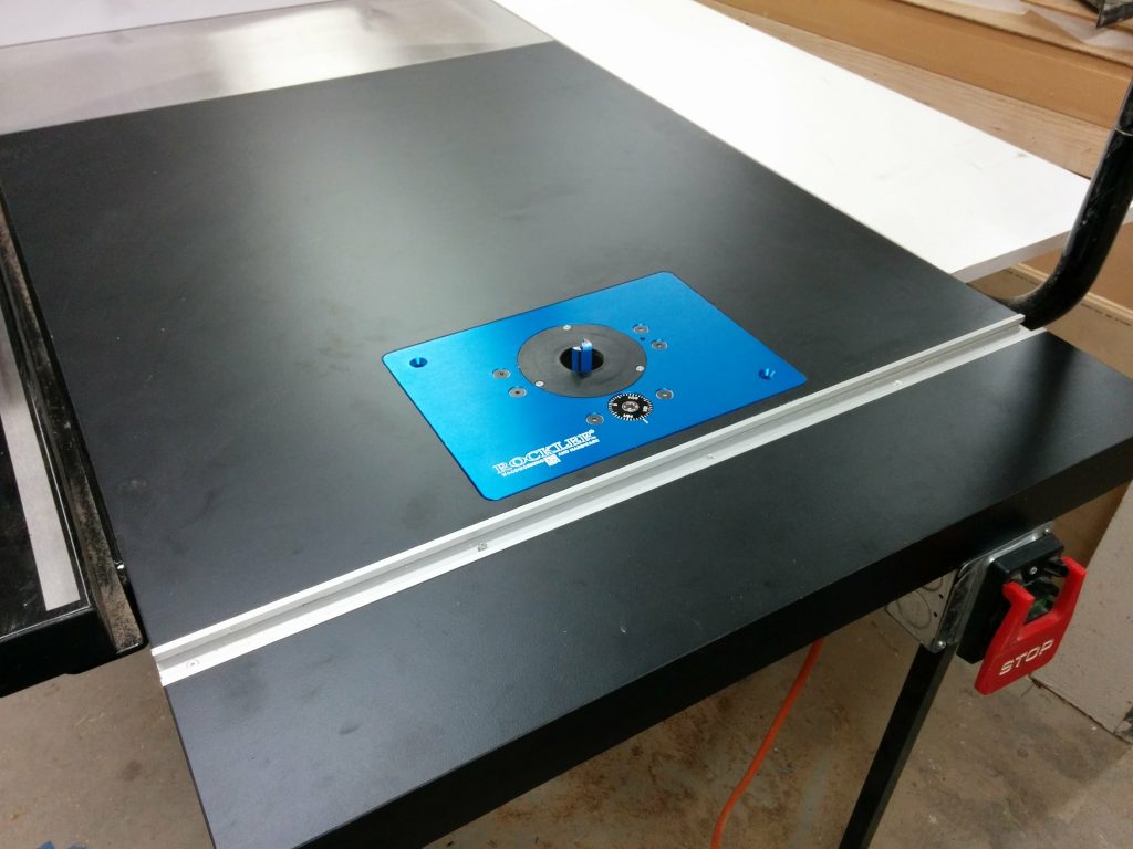
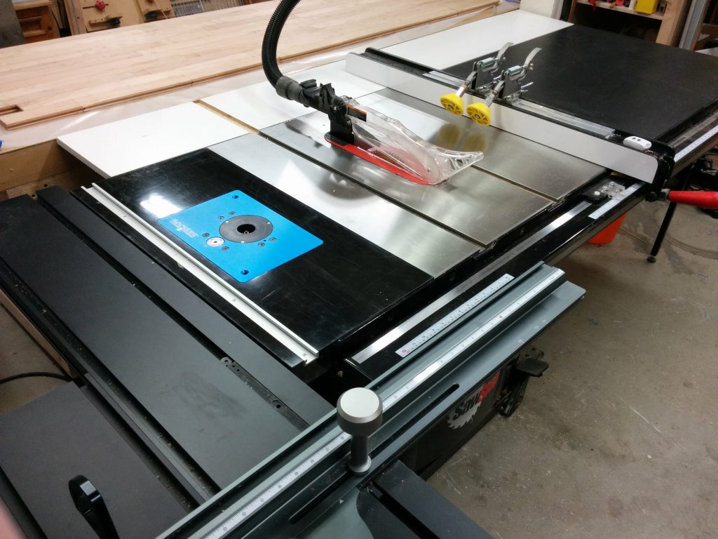
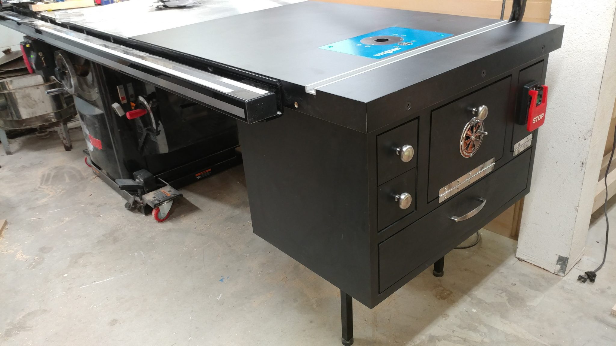
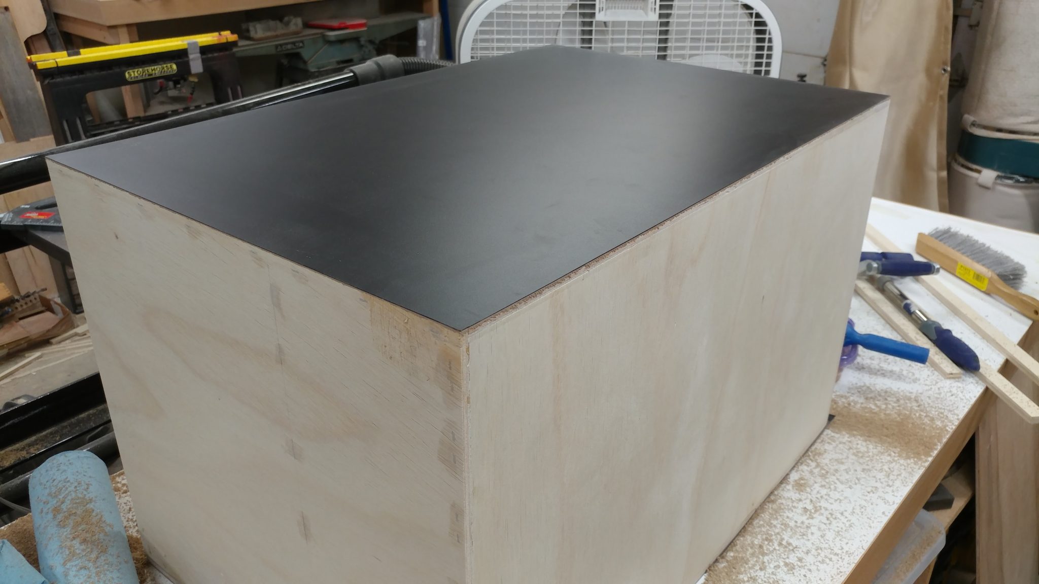
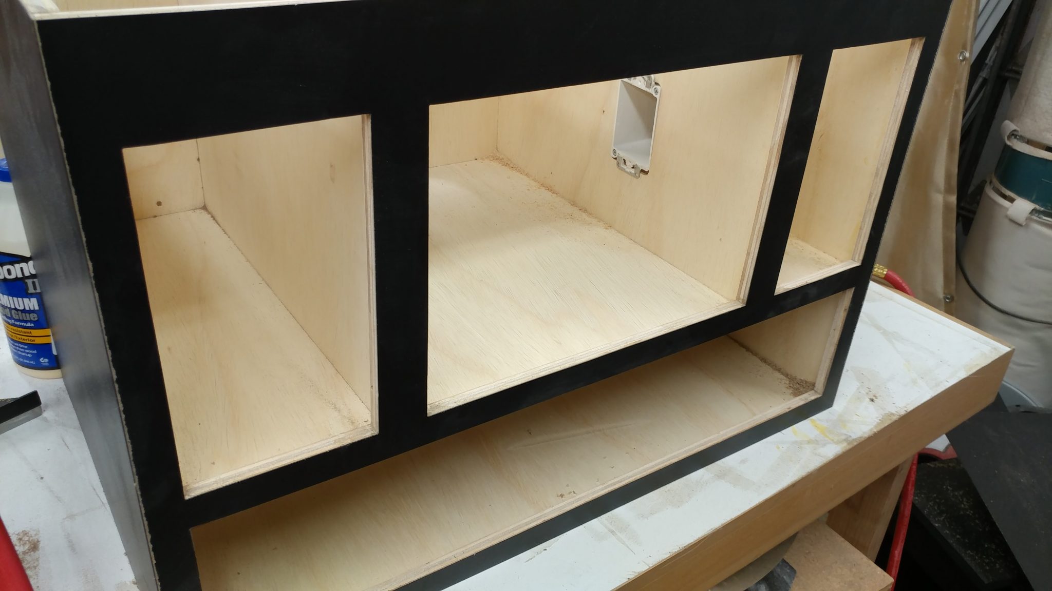
So you can see what I have in mind, here’s a sneak peek of the finished enclosure.
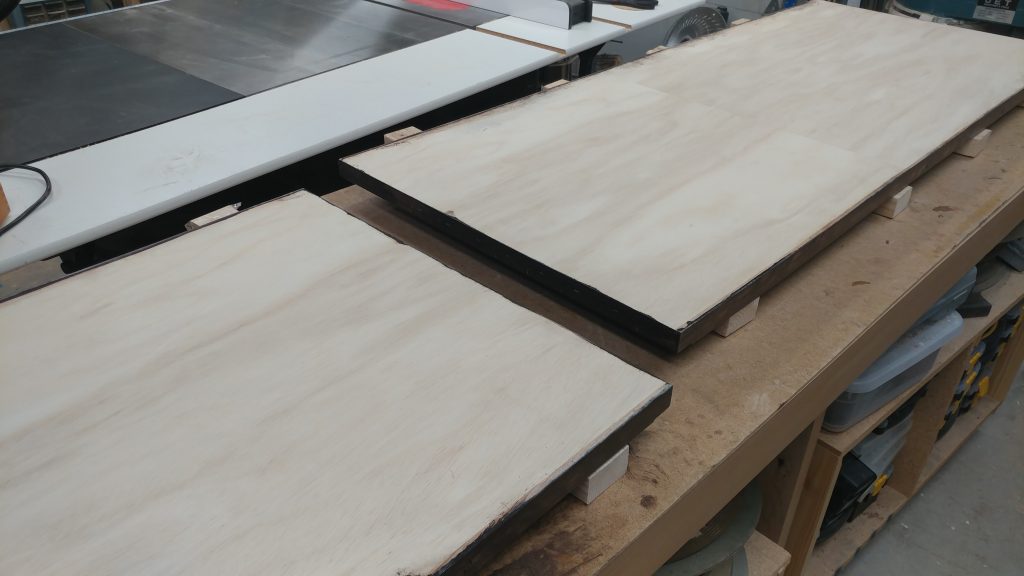
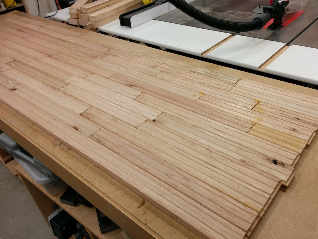
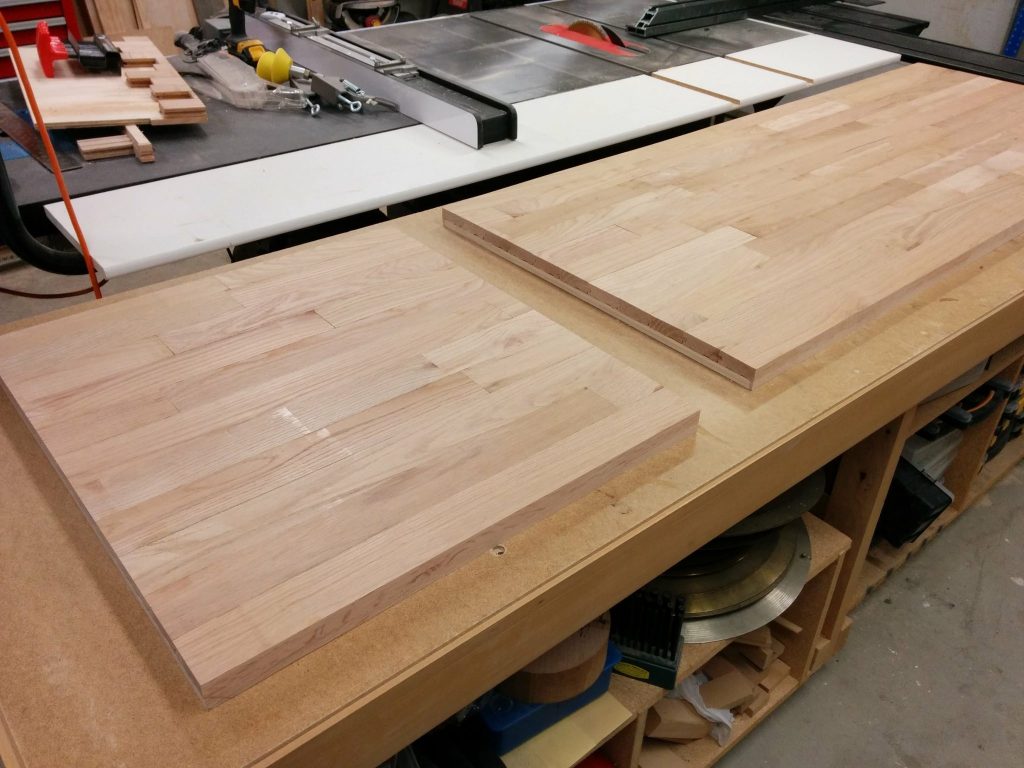
Preparing the table for the laminate
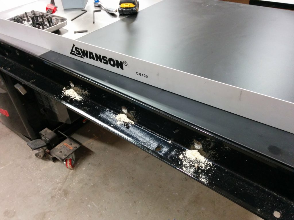
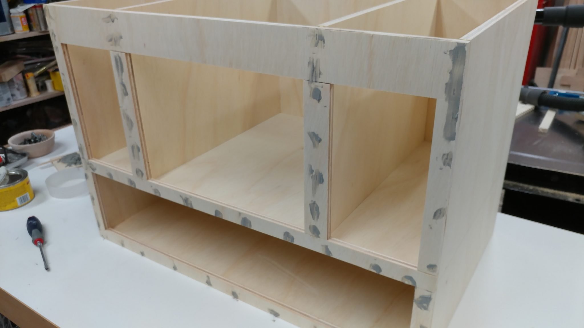
Before applying laminate, I always like to make the work surface fairly smooth. The first step to accomplishing this is to fill in the nail holes and any other gaps with wood filler. I actually would normally use Bondo for this but this time I’m using MinWax Wood Filler which is basically just beige-colored Bondo.
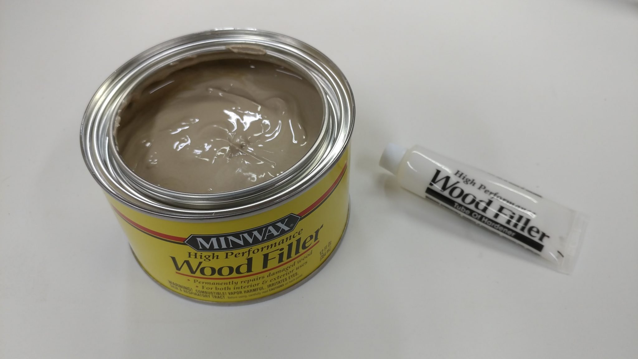
Like Bondo, the MinWax Wood Filler is mixed together from two parts.
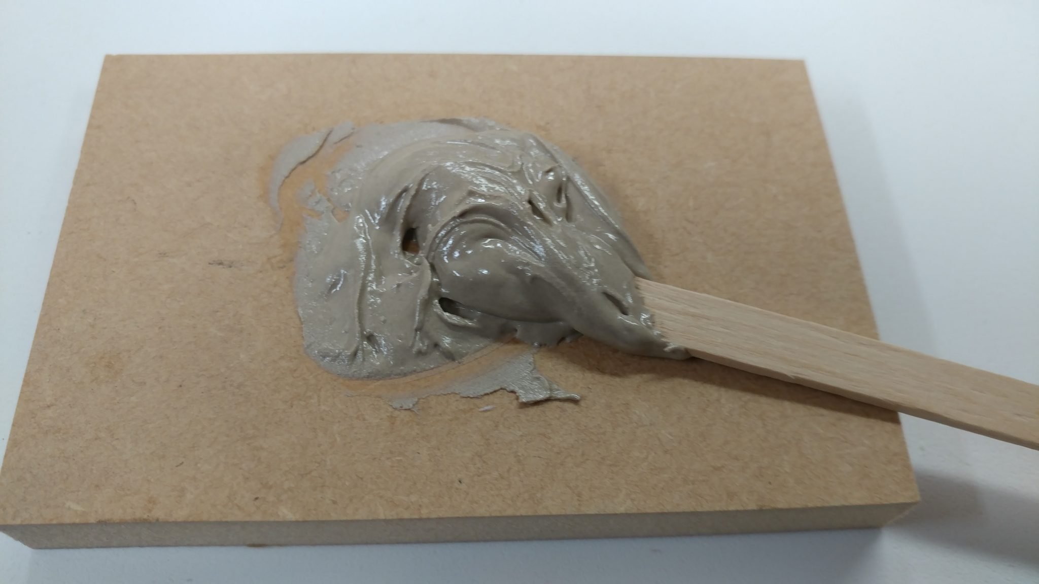
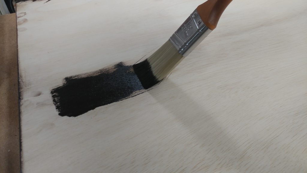
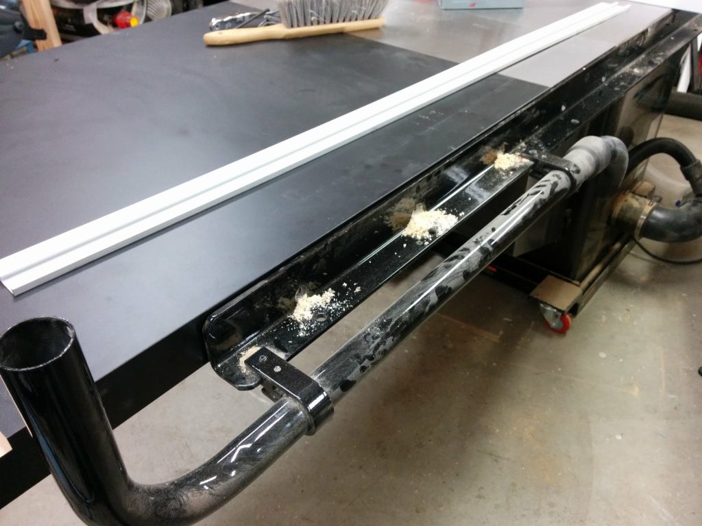
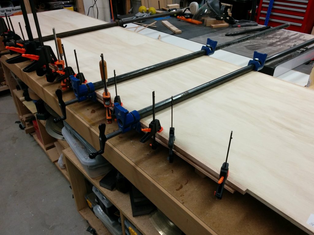
I applied the wood filler and let it set for about 15 minutes.
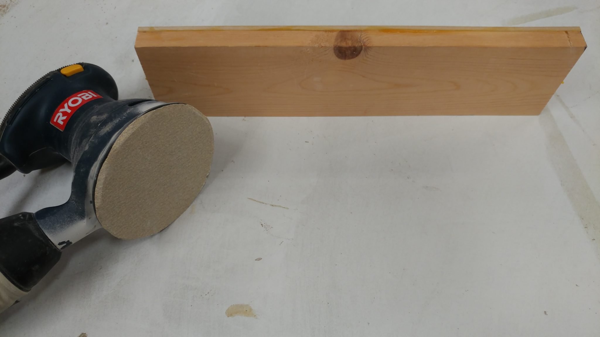
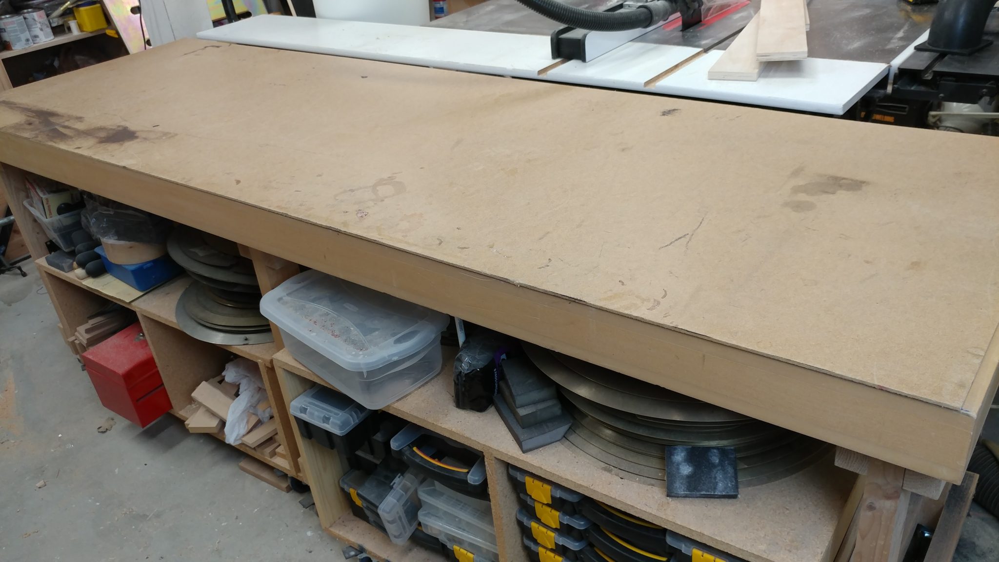
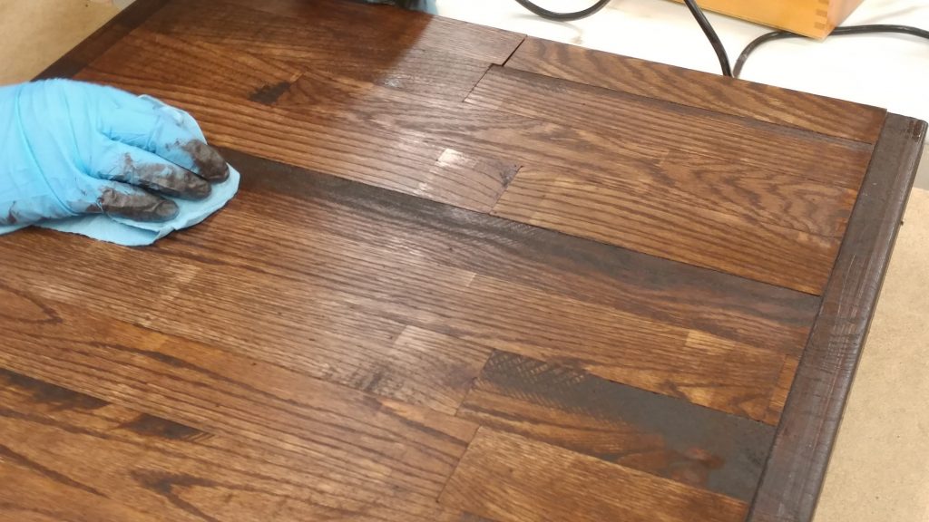
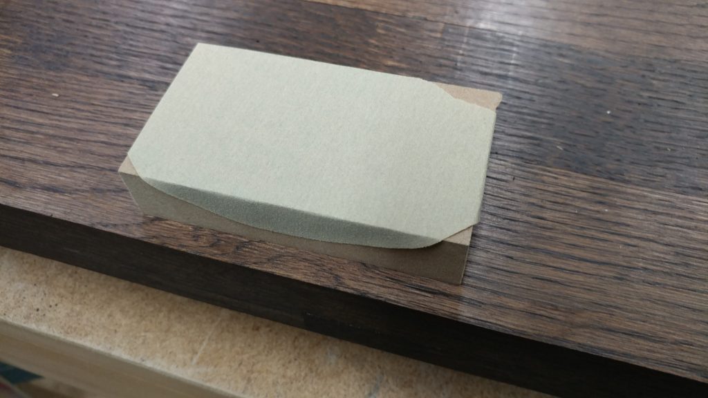
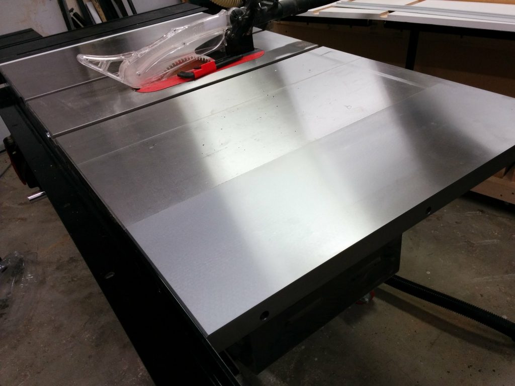
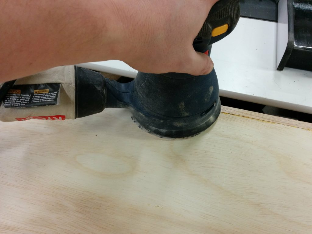
Once the wood filler was cured, I took a random orbital sander to it.
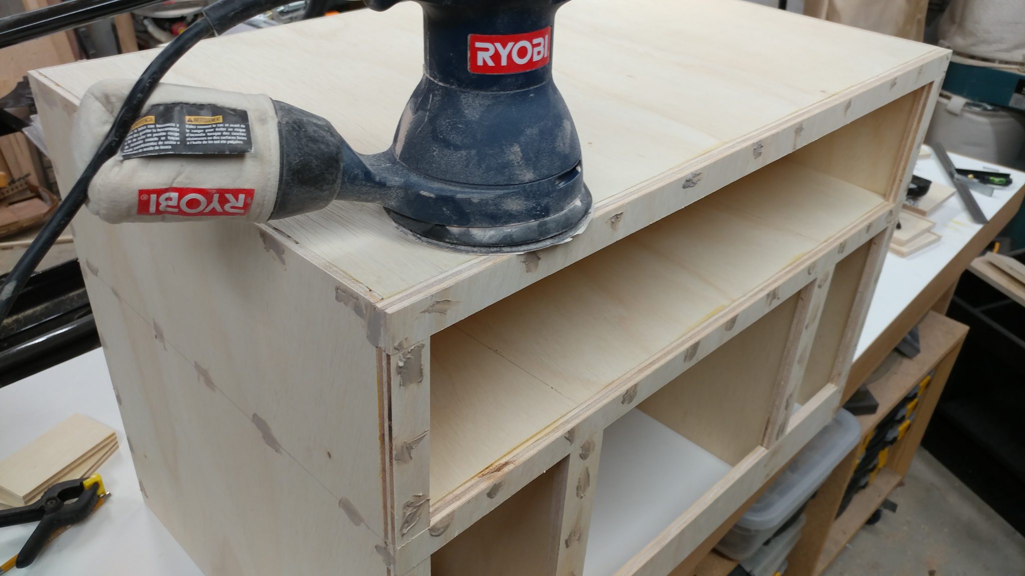
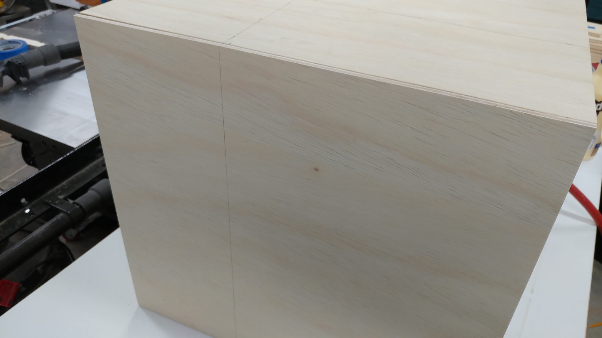
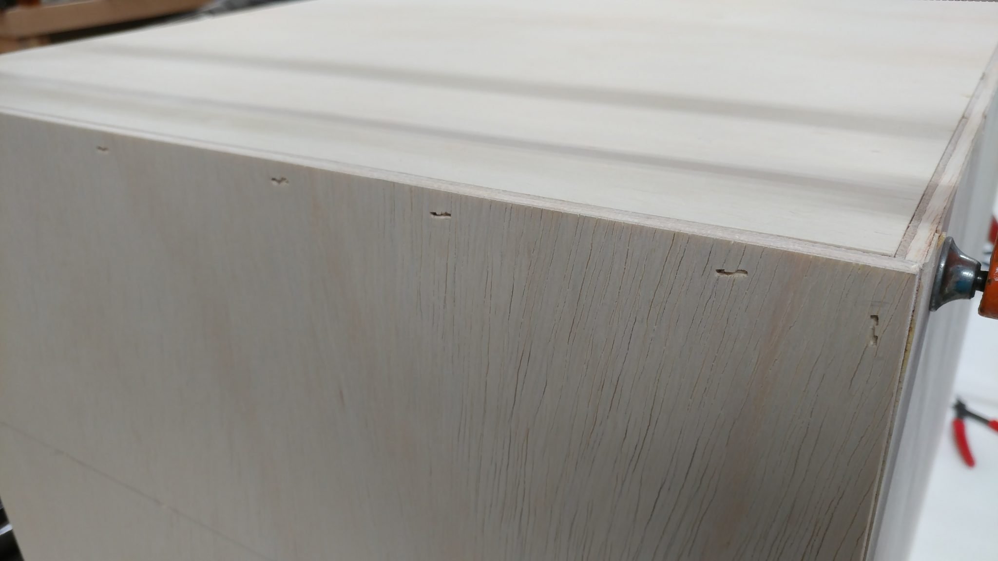
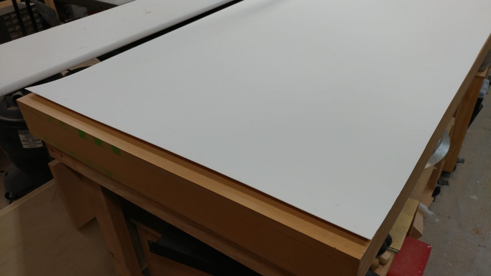
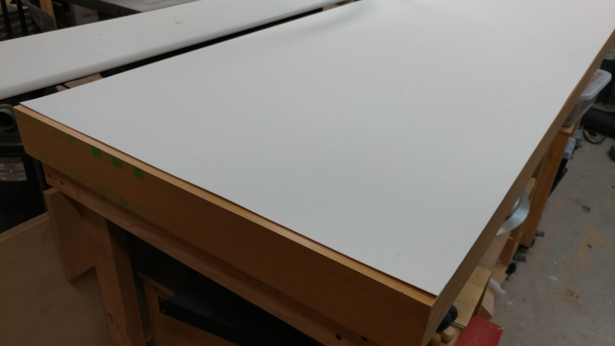
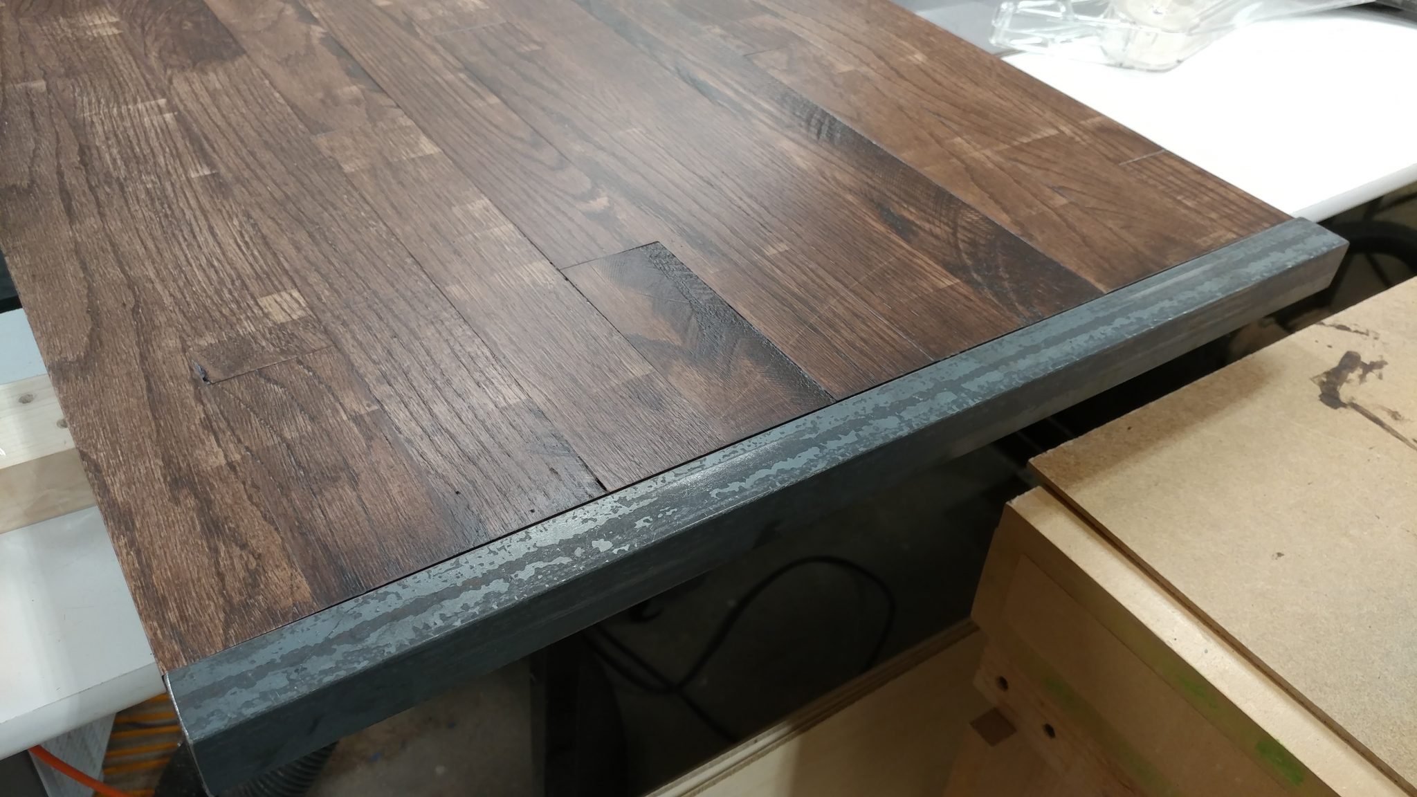
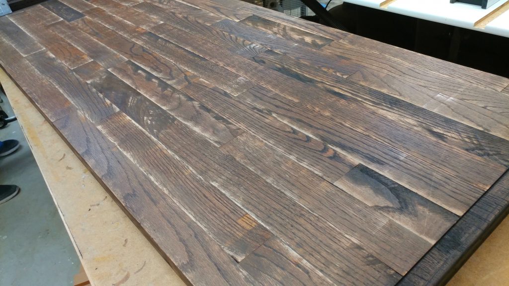
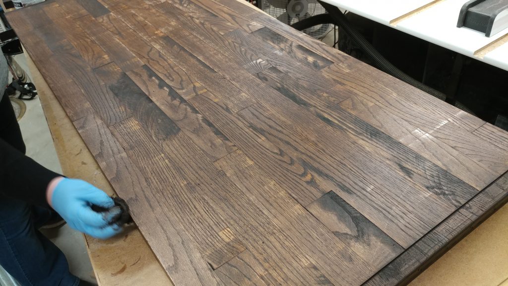
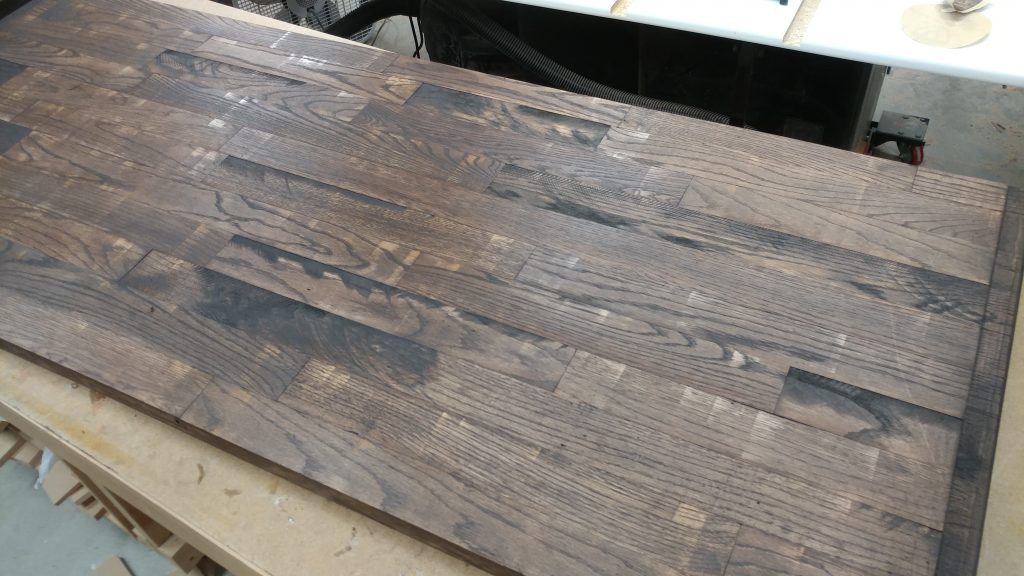
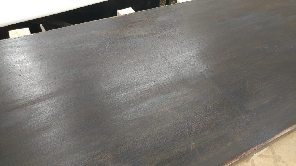
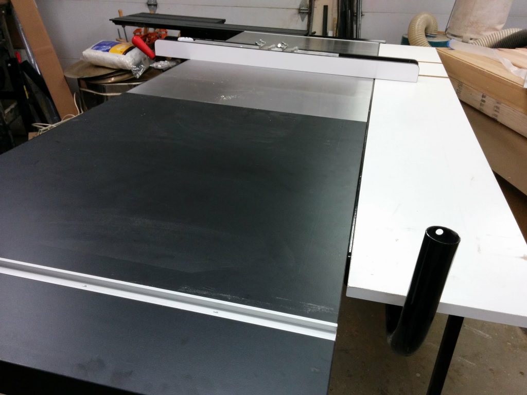
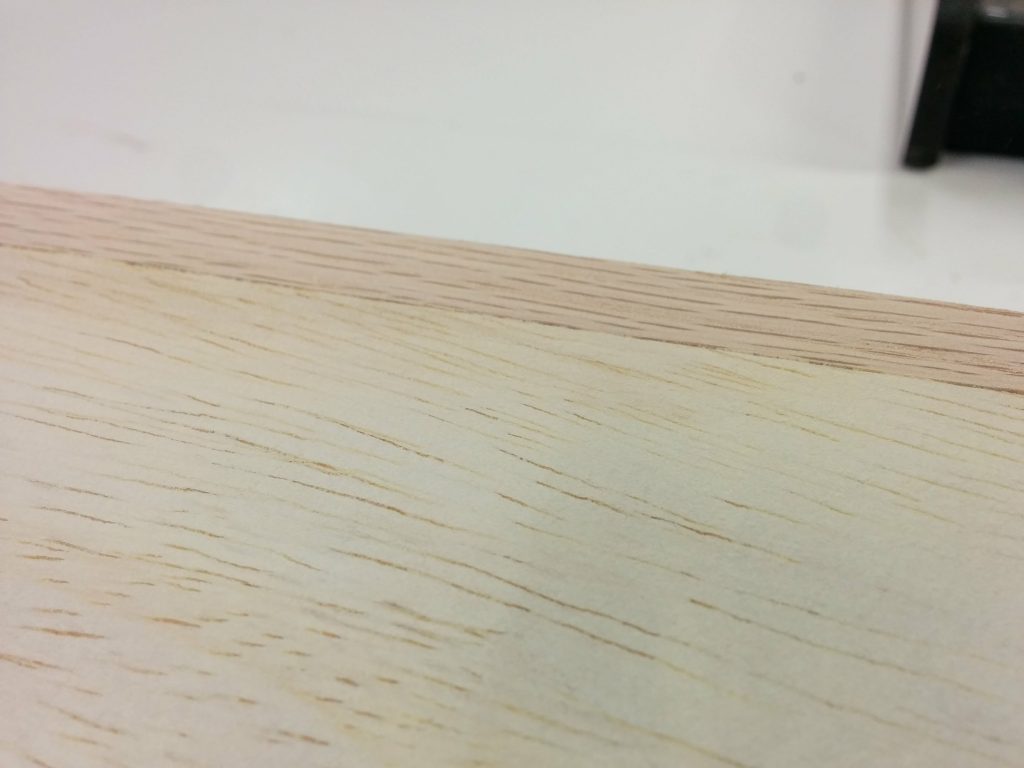
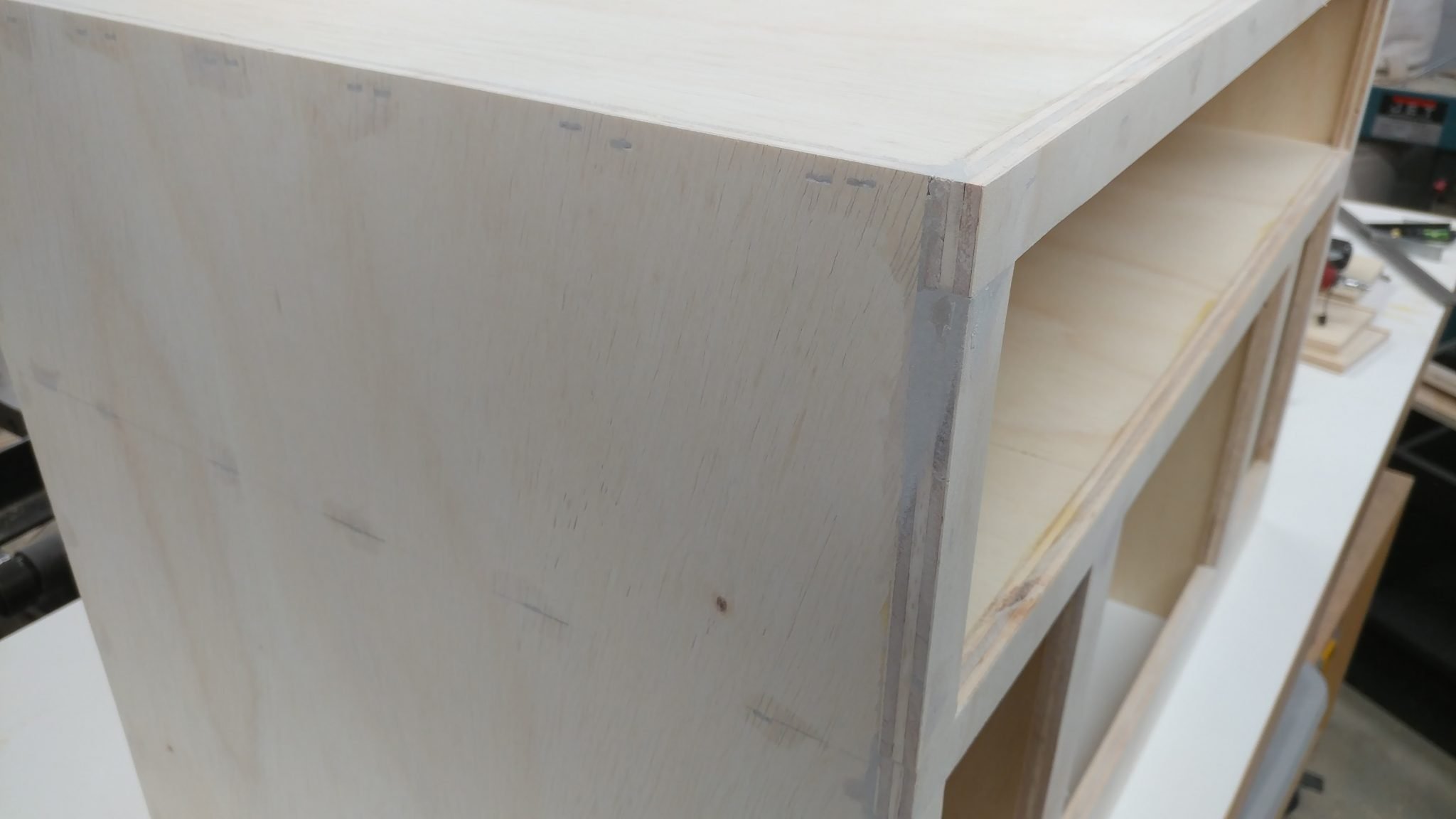
The surface is now flat and smooth.
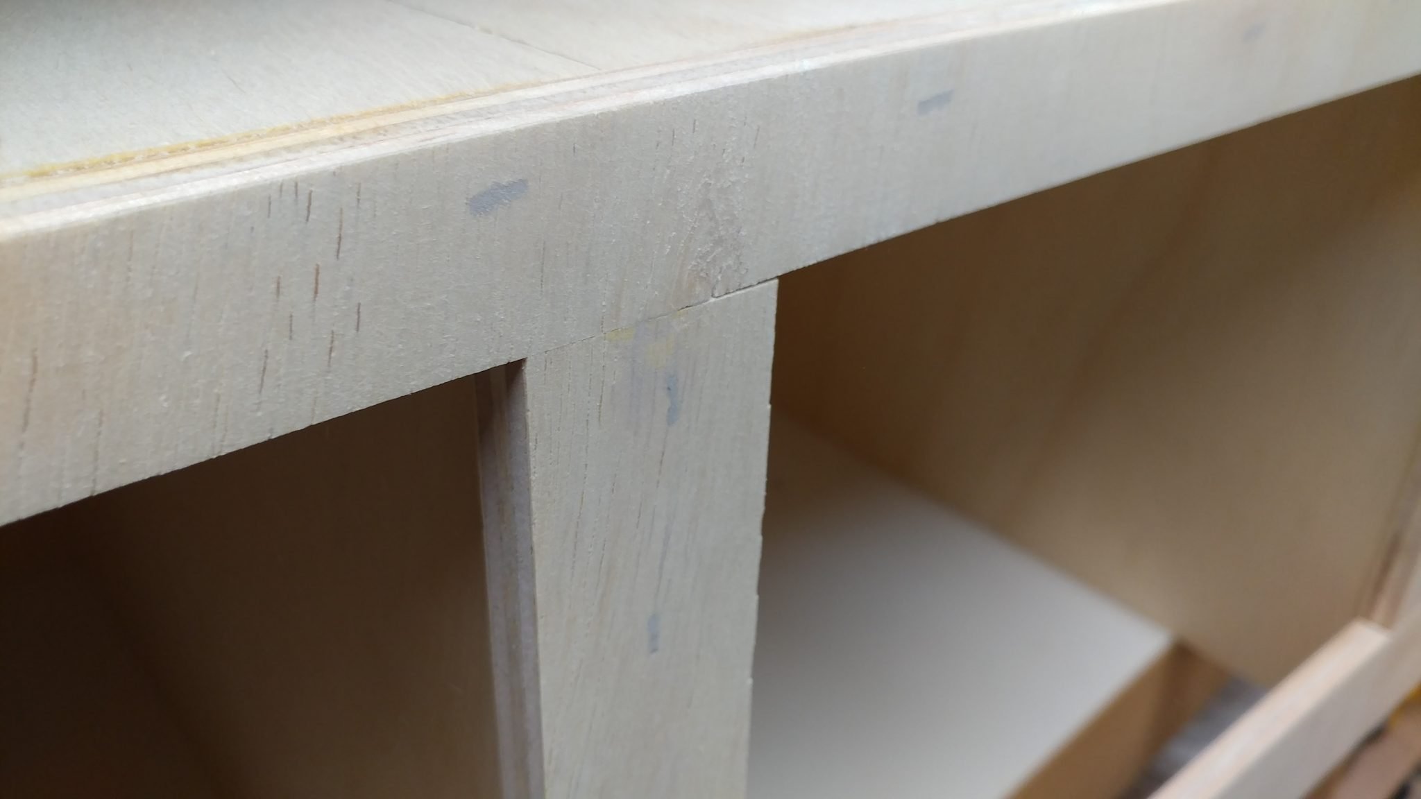
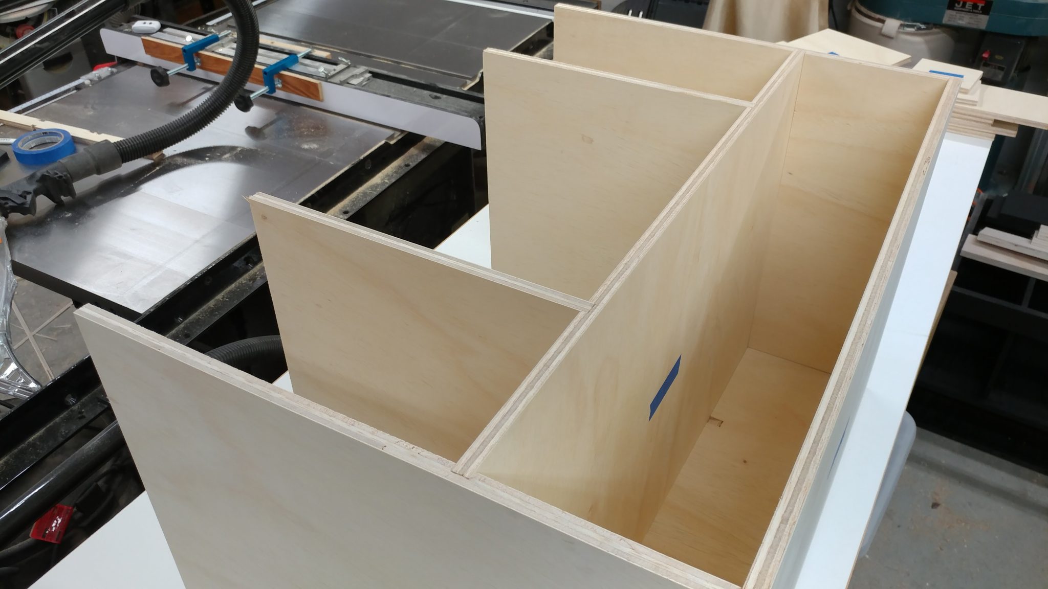
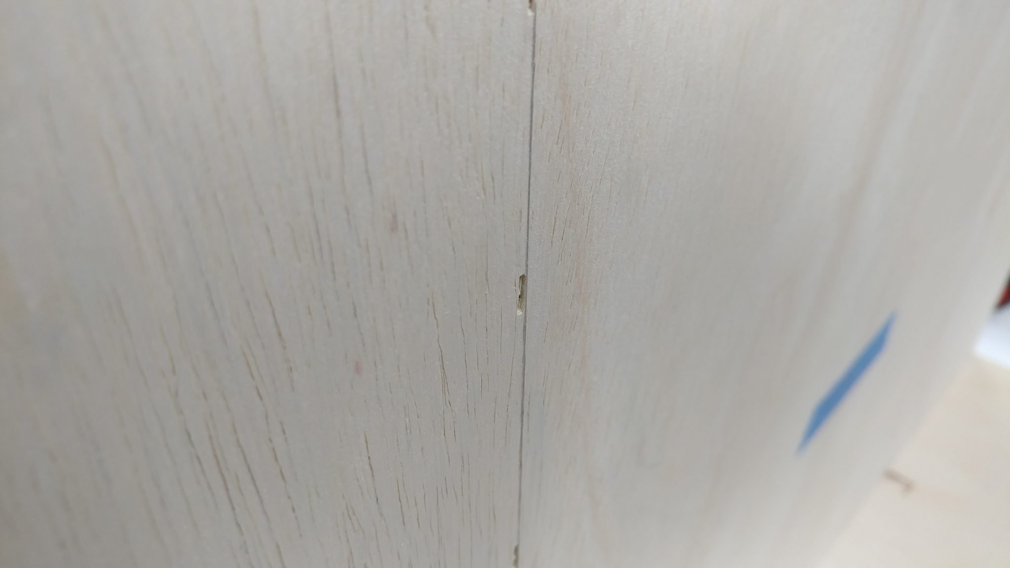
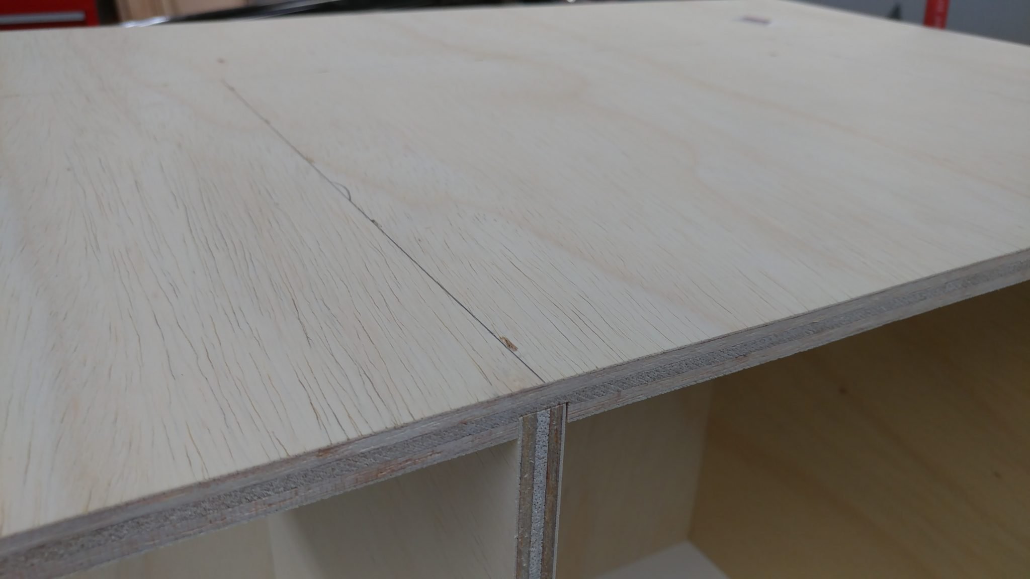
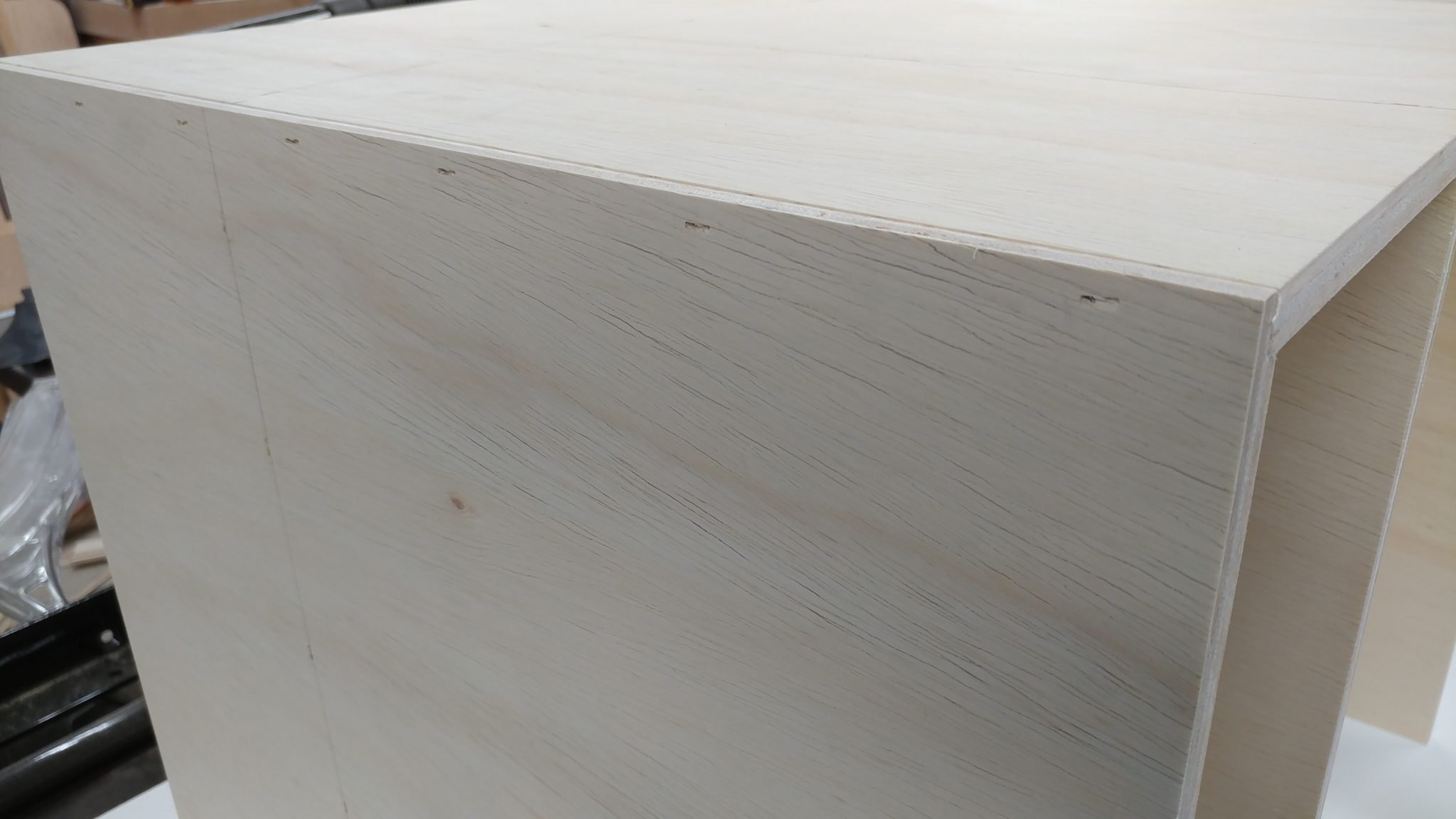
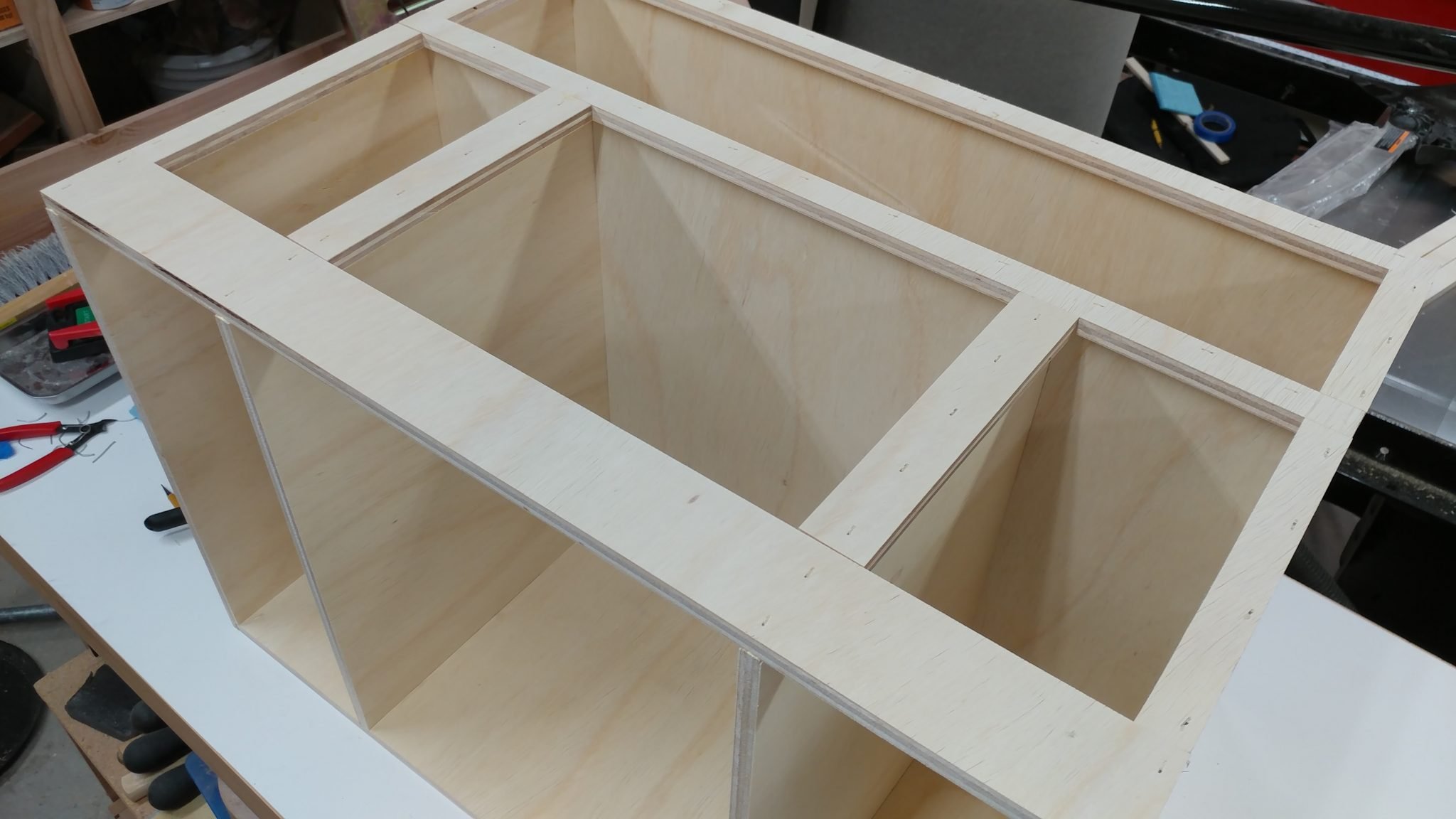
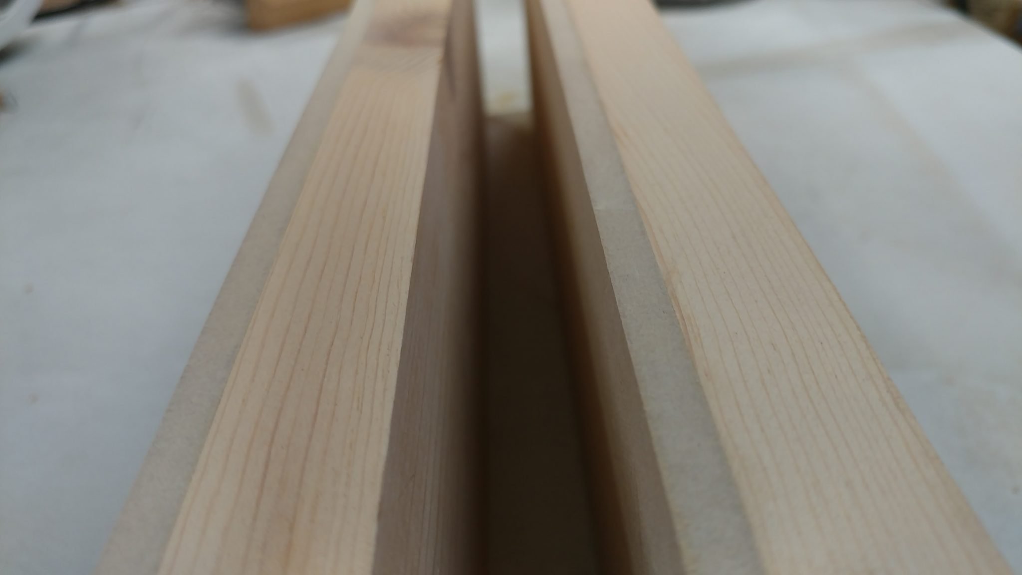
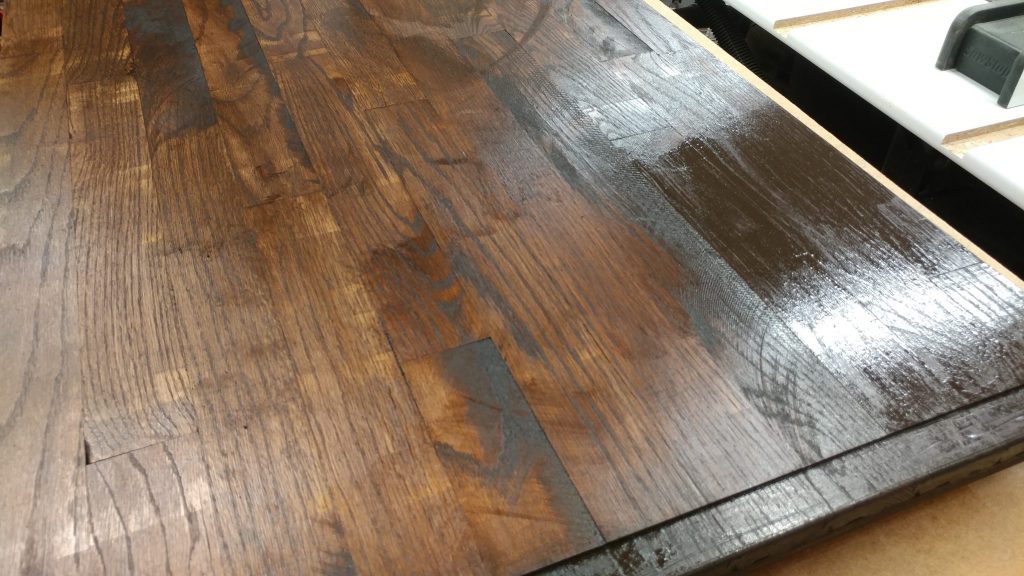
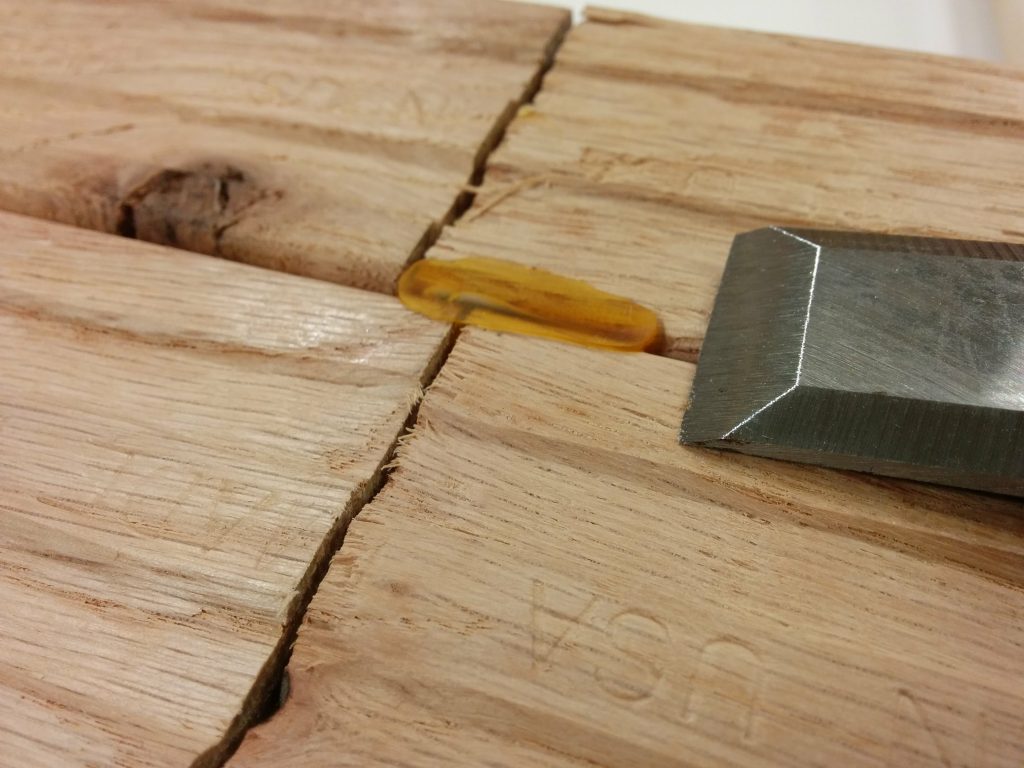
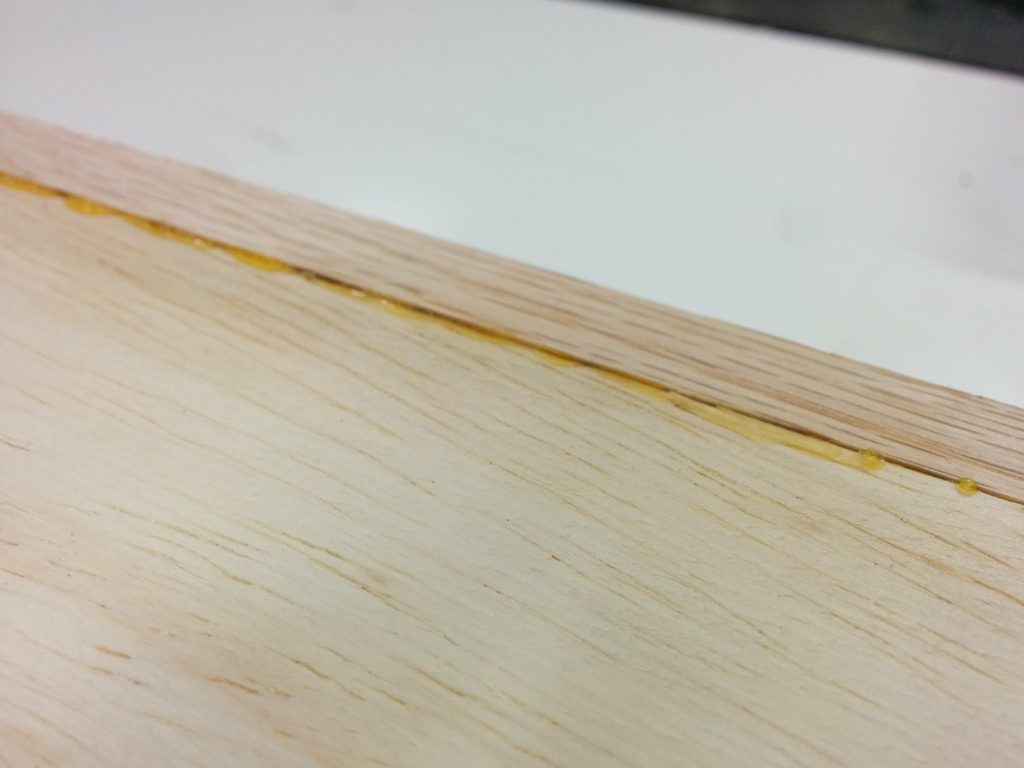
There were a few areas where the individual pieces of the front didn’t quite line up and made gaps. I packed those full of wood filler and then sanded it down.
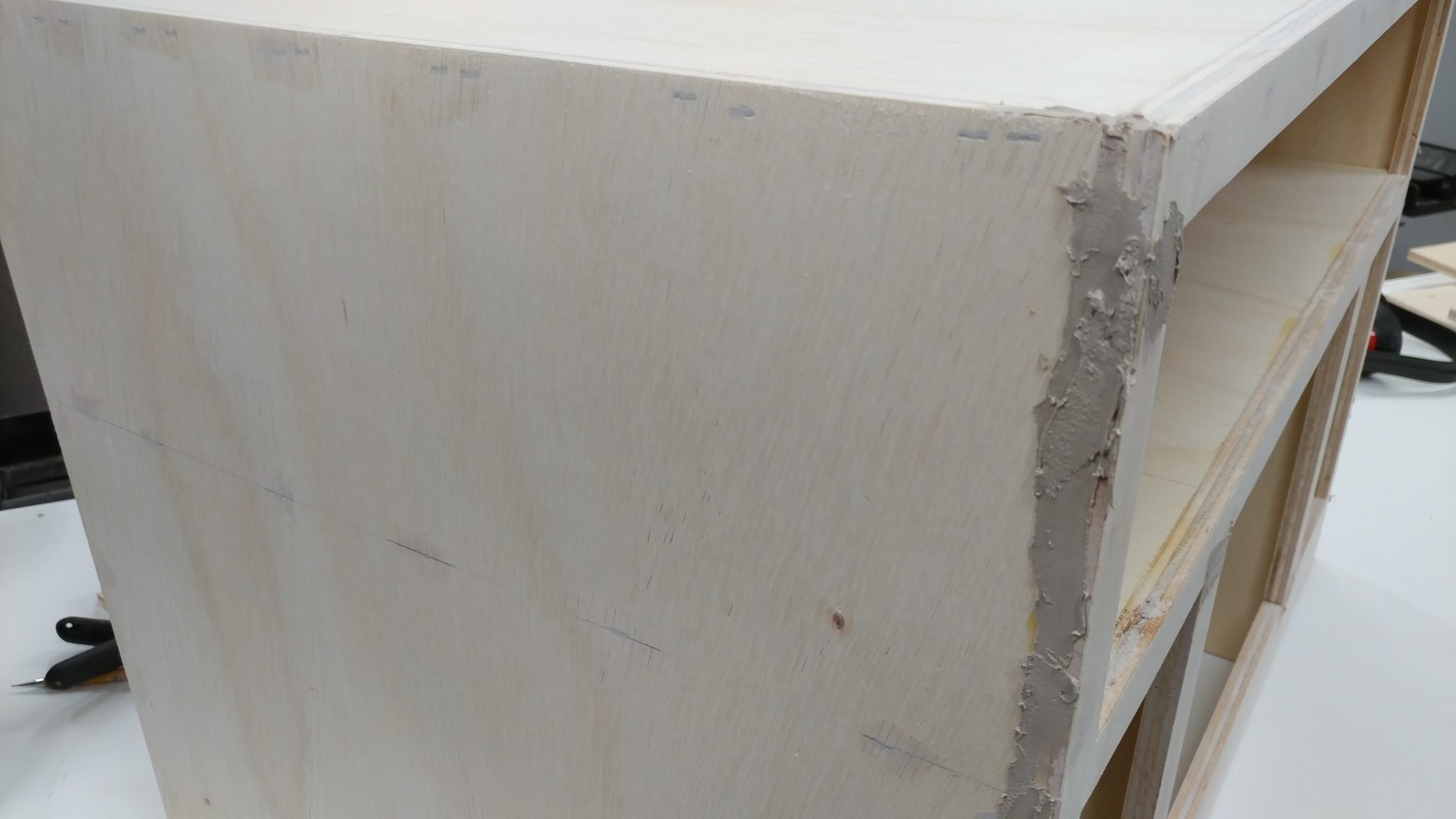
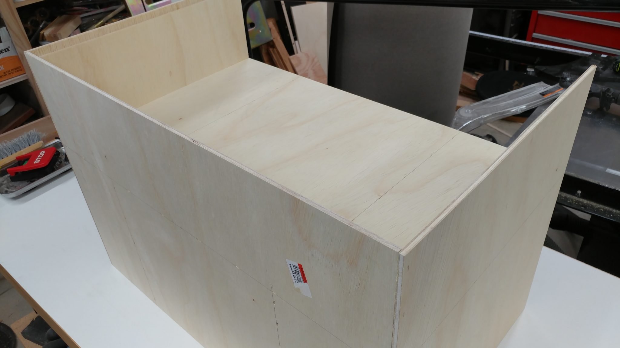
This results in a pretty smooth cabinet.
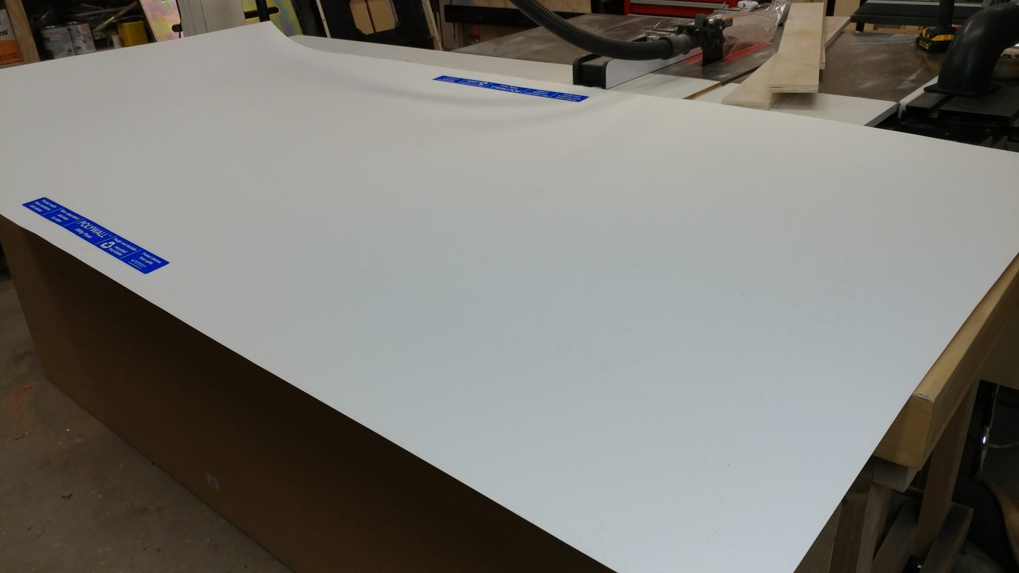
Cutting the laminate
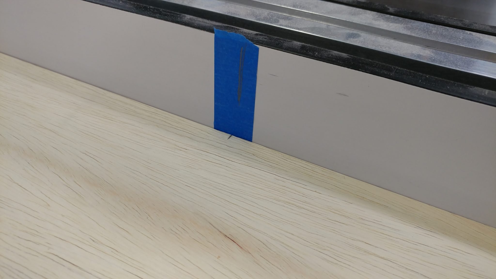
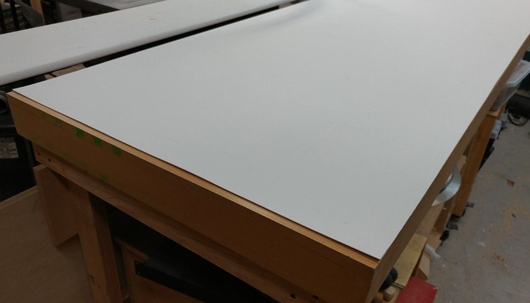
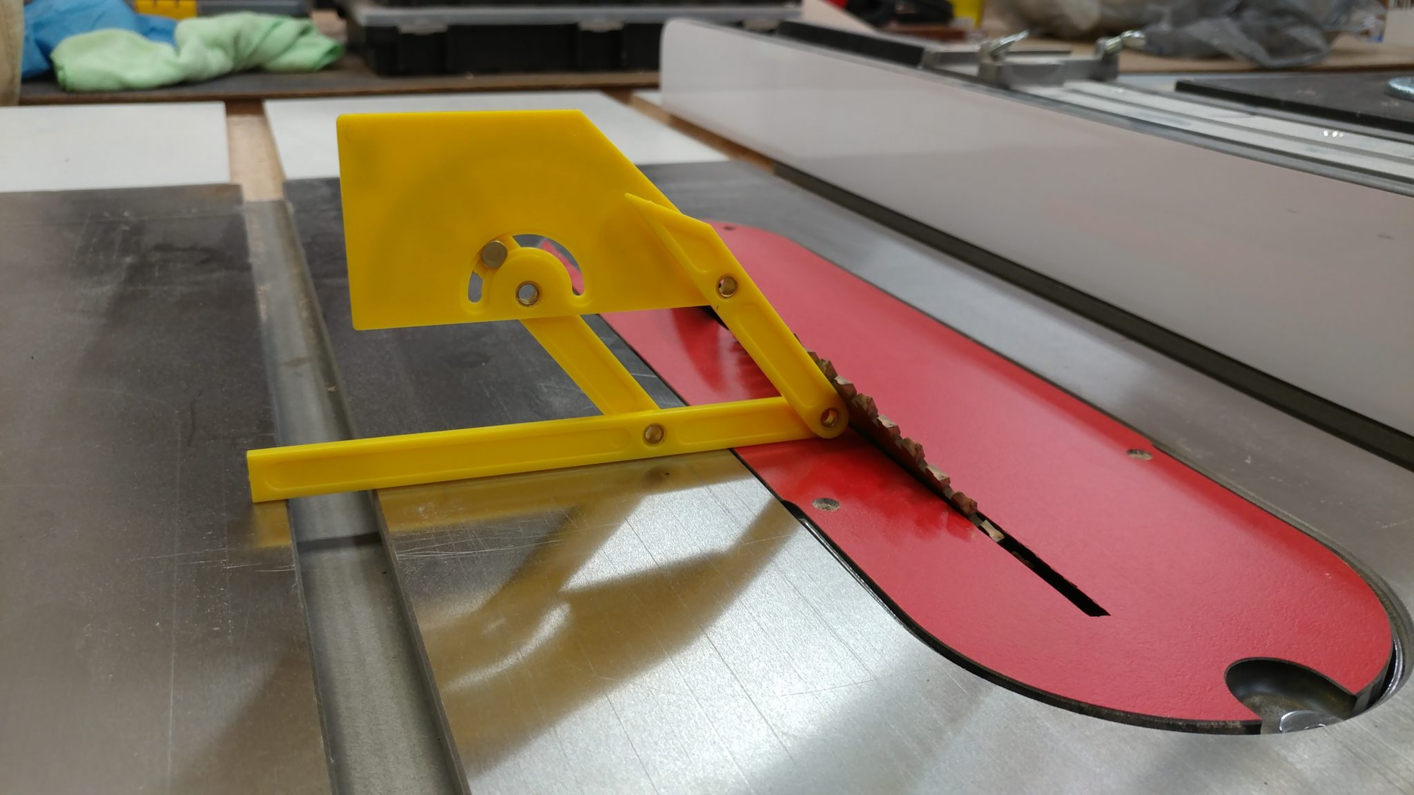
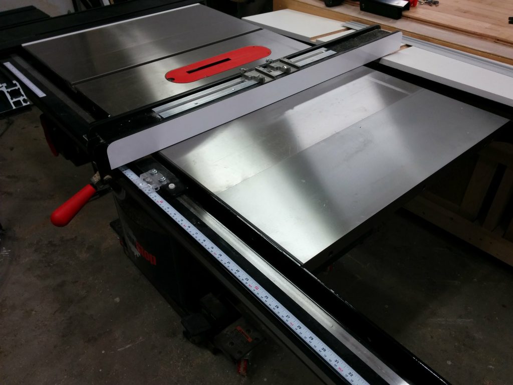
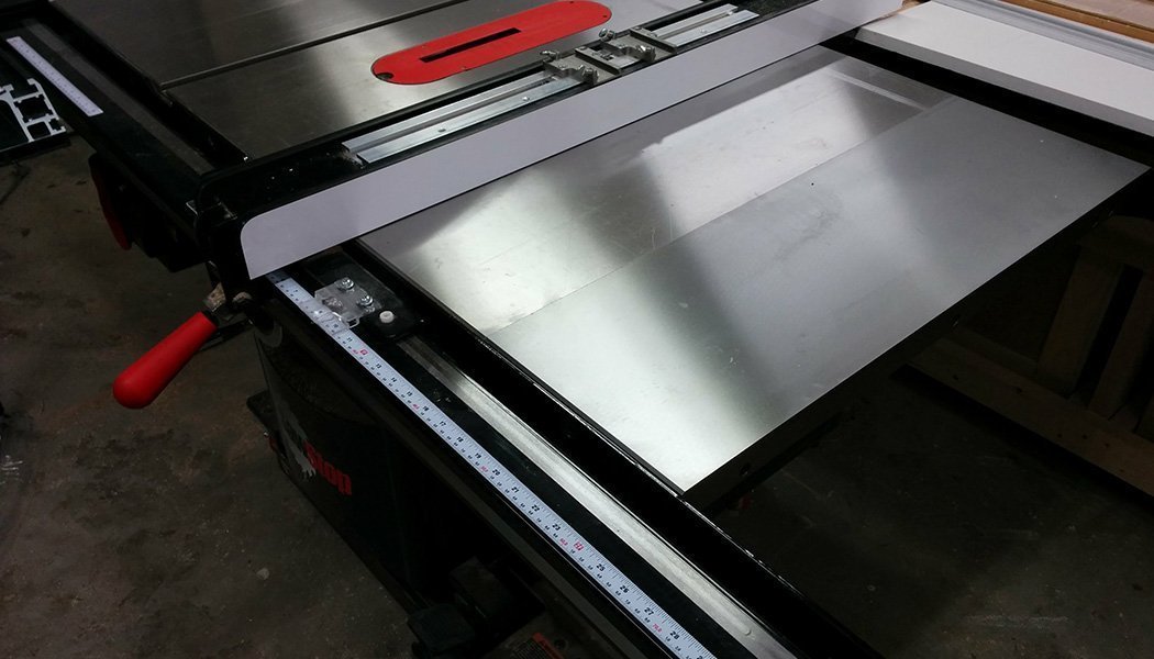
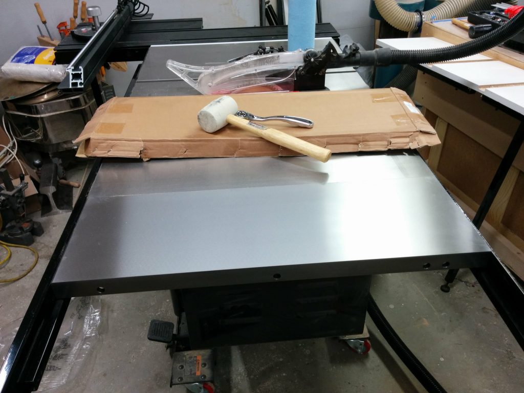
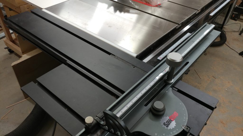
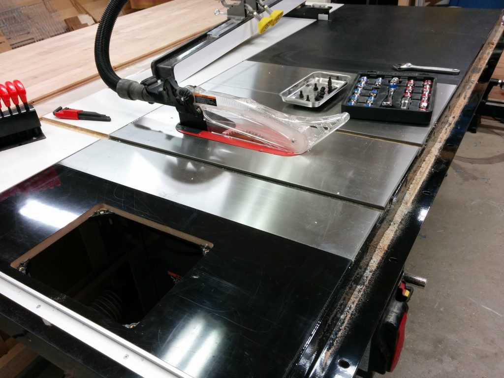
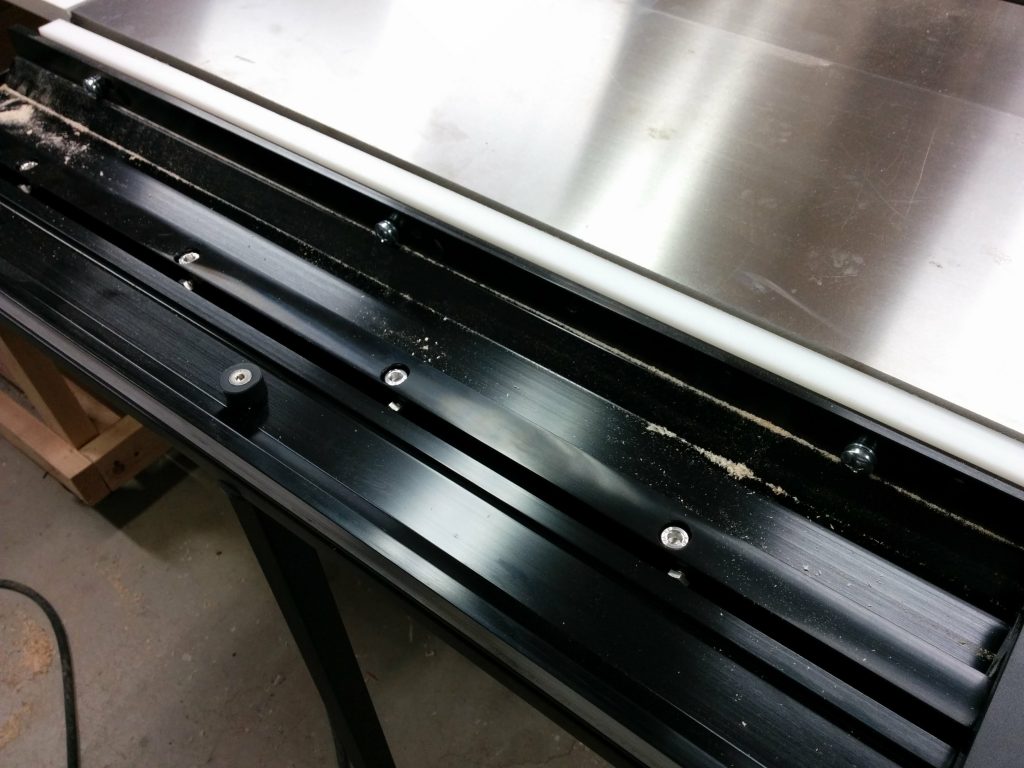
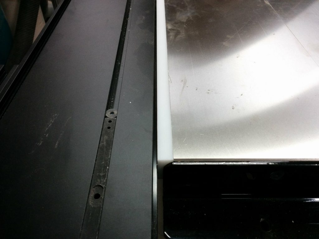
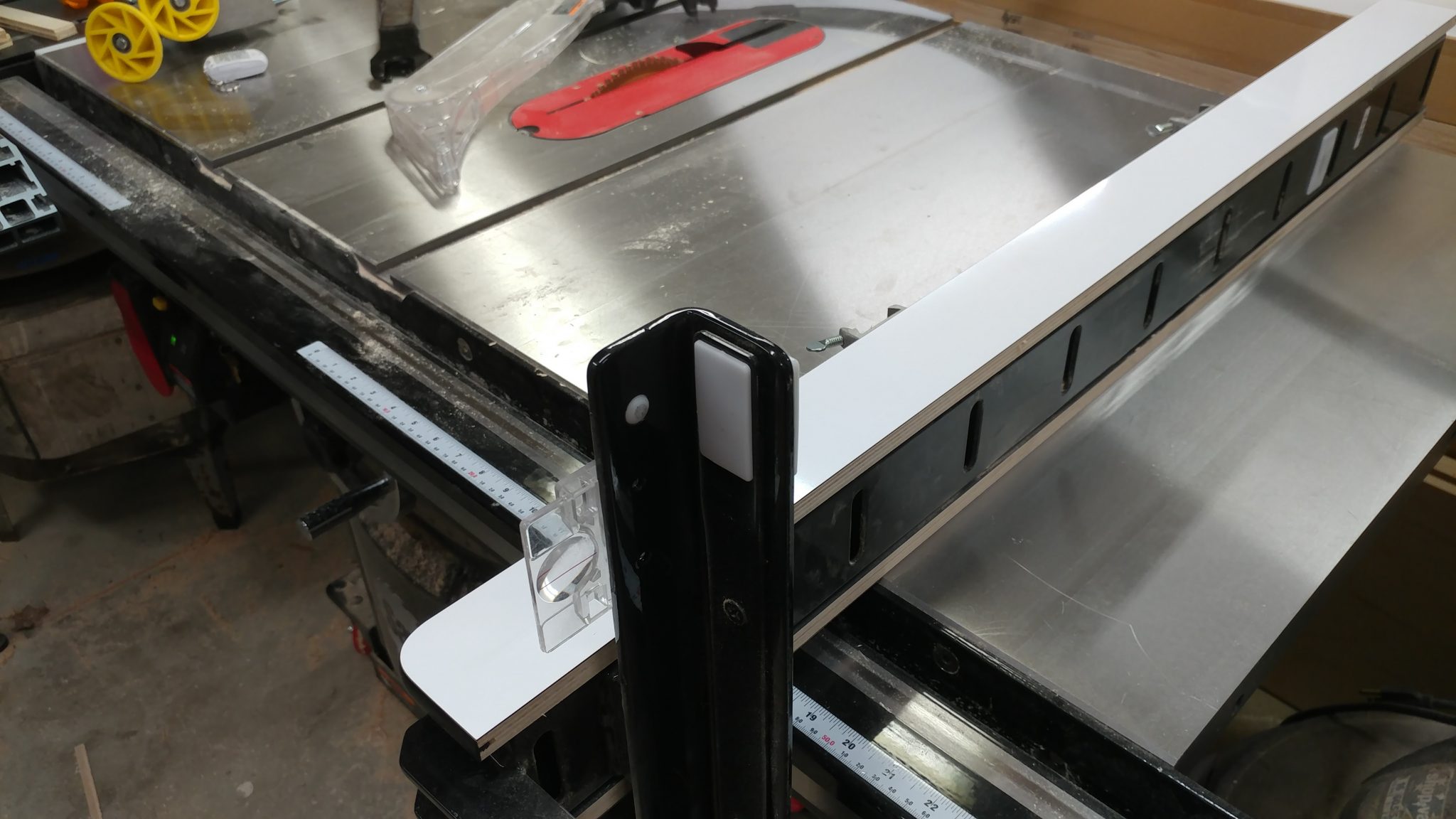
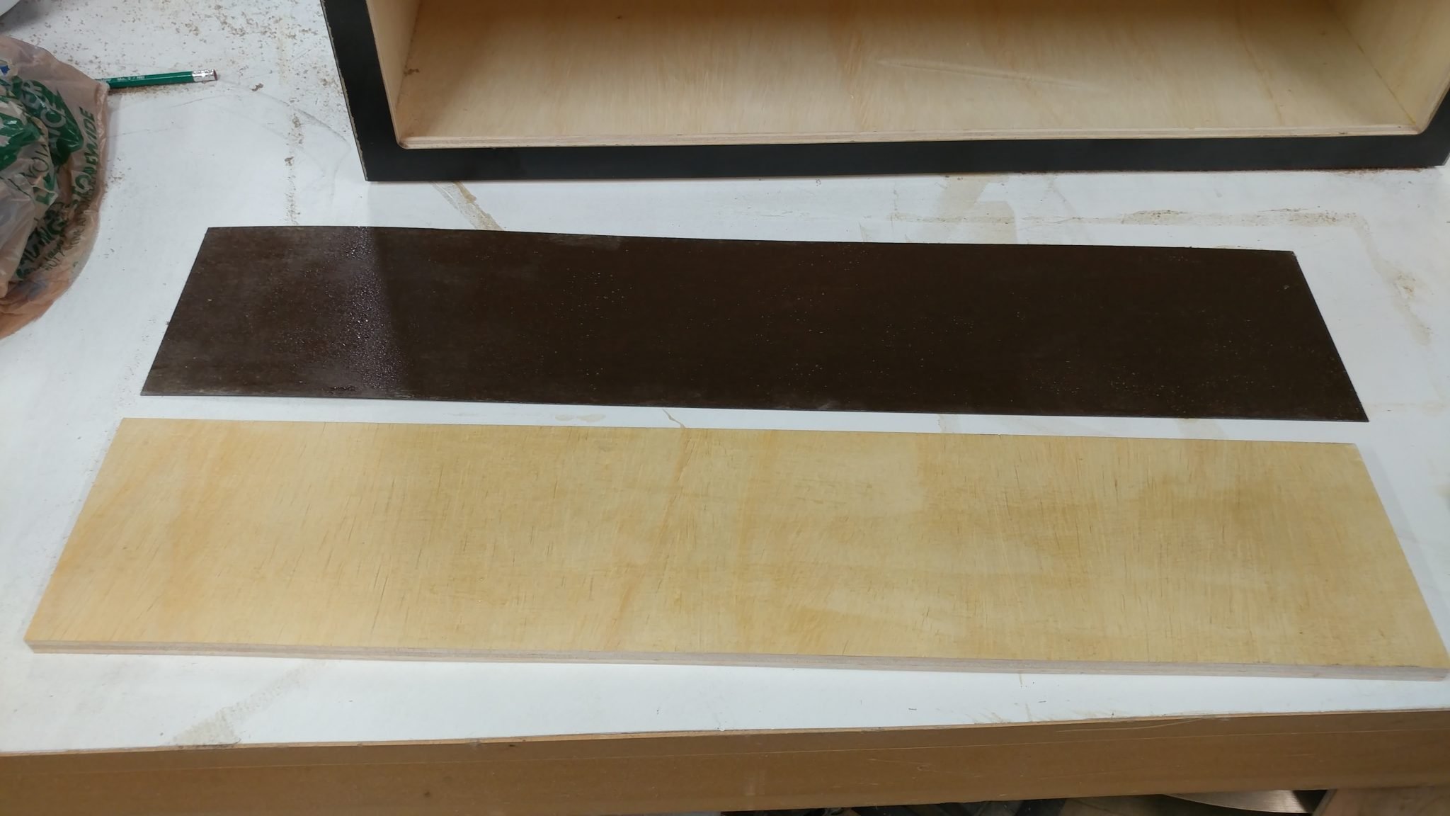
I found that Home Depot carries a matte black Formica laminate that perfectly matches the laminate used on the SawStop extension table so I picked up a sheet of that to use. Normally I like to have a small gap at the bottom of the faceplate on my table saw fence but as you can see, this is going to be a problem when cutting laminate. I’m going to have to bring the faceplate down as far as I can, otherwise the laminate may slide under the faceplate rather than ride against it.
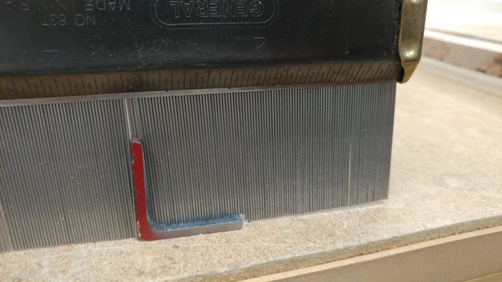
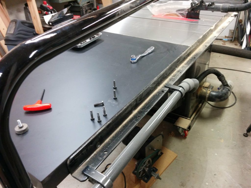
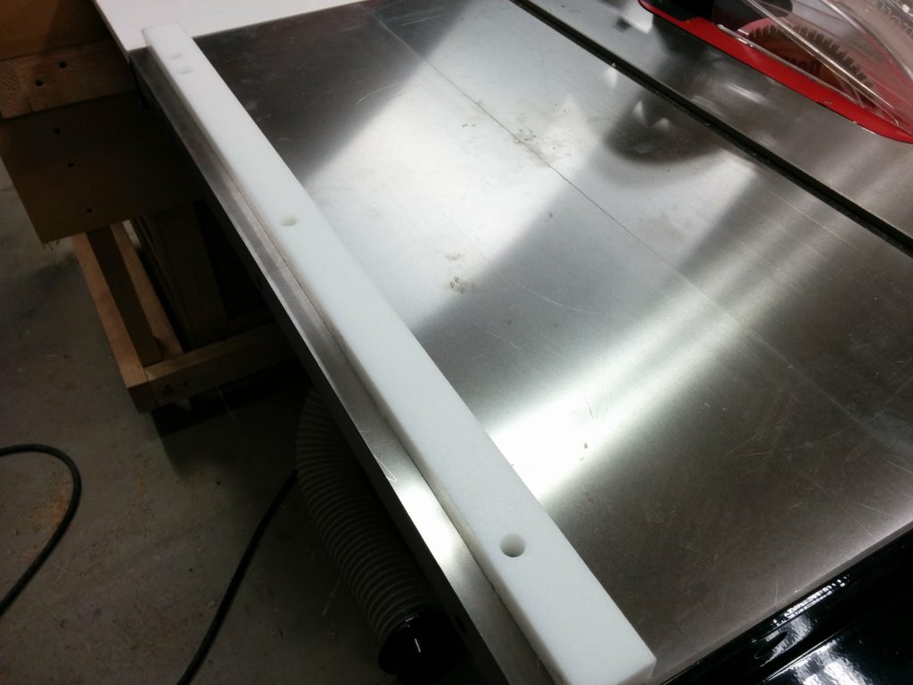
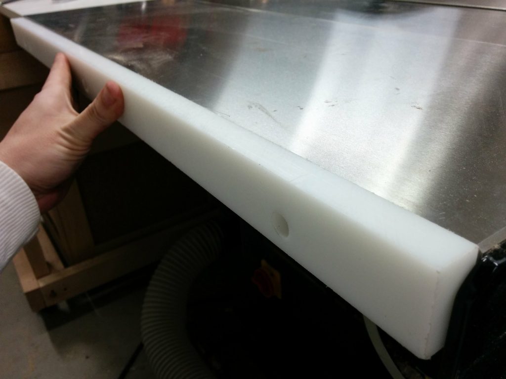
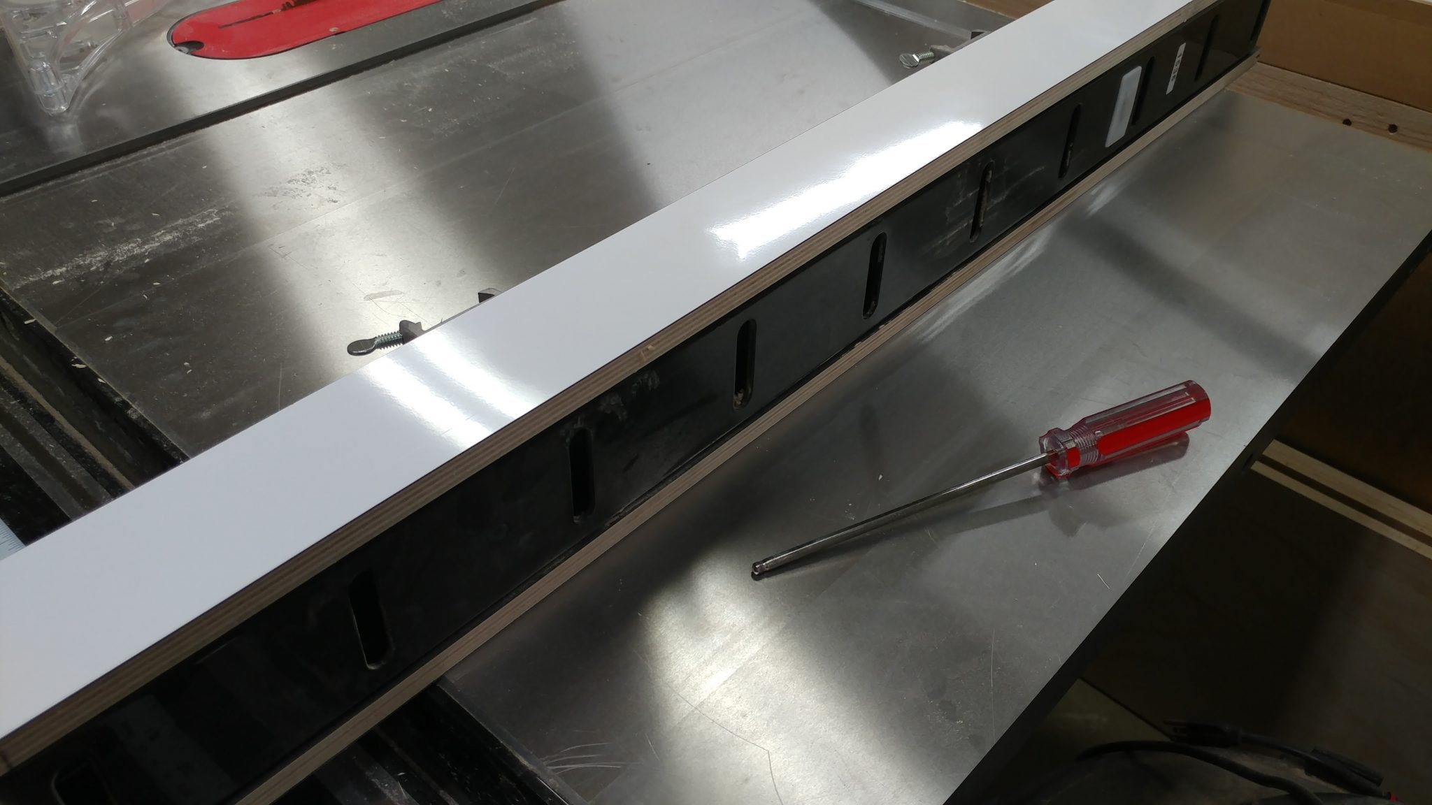
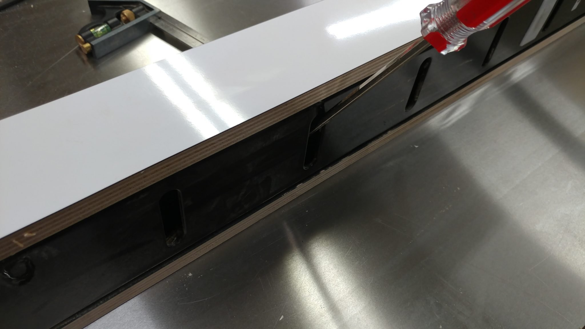
To adjust the faceplate on a SawStop fence you need to loosen the 5mm allen bolts which are accessible from the underside of the main fence body. Start by turning the fence on its side with the faceplate you want to adjust facing down.
You will need a 5mm ball-end allen wrench.
The ball-end on the wrench allows you to access the bolts at an angle. You don’t need to remove them, just loosen them a bit.
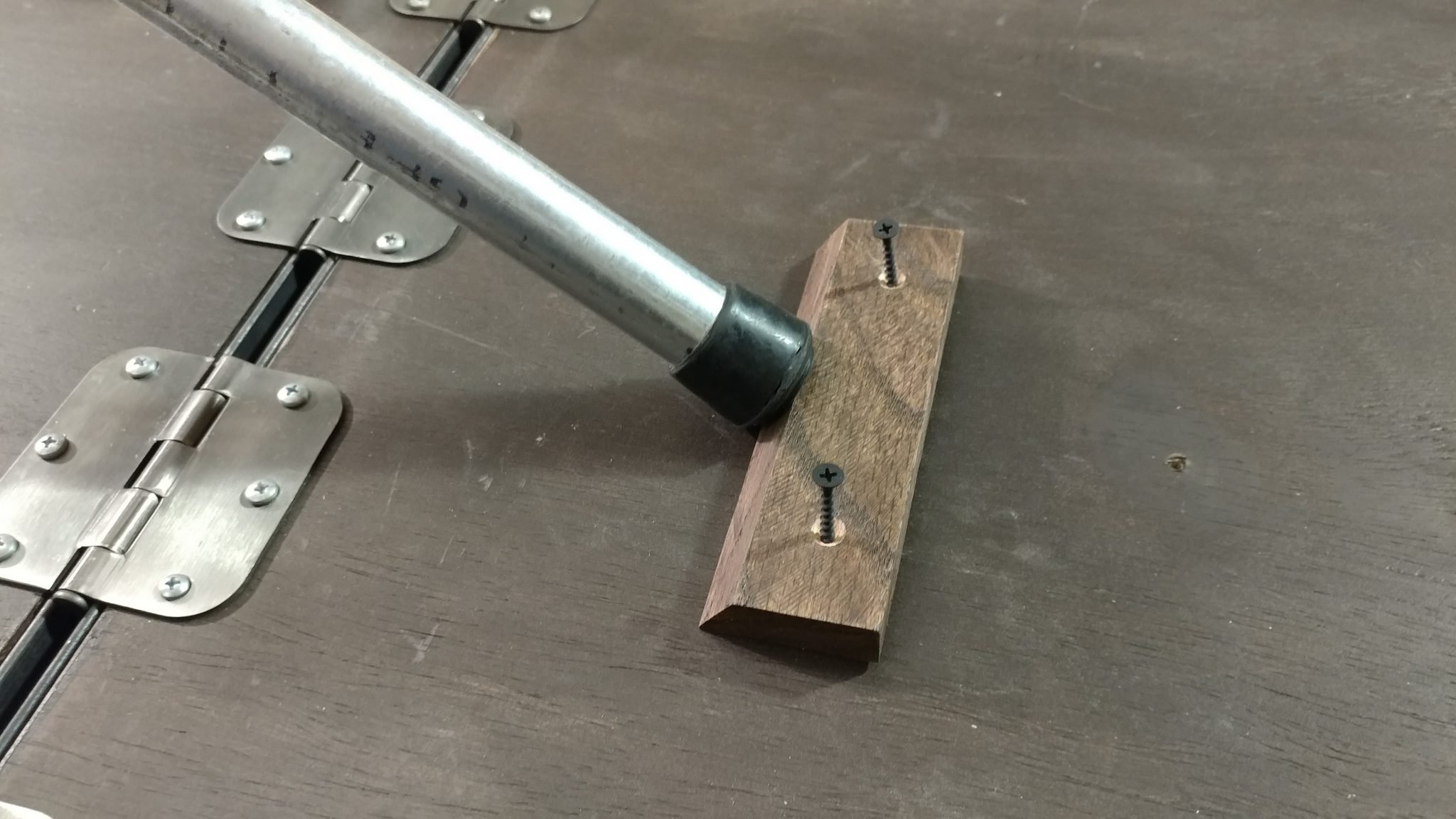
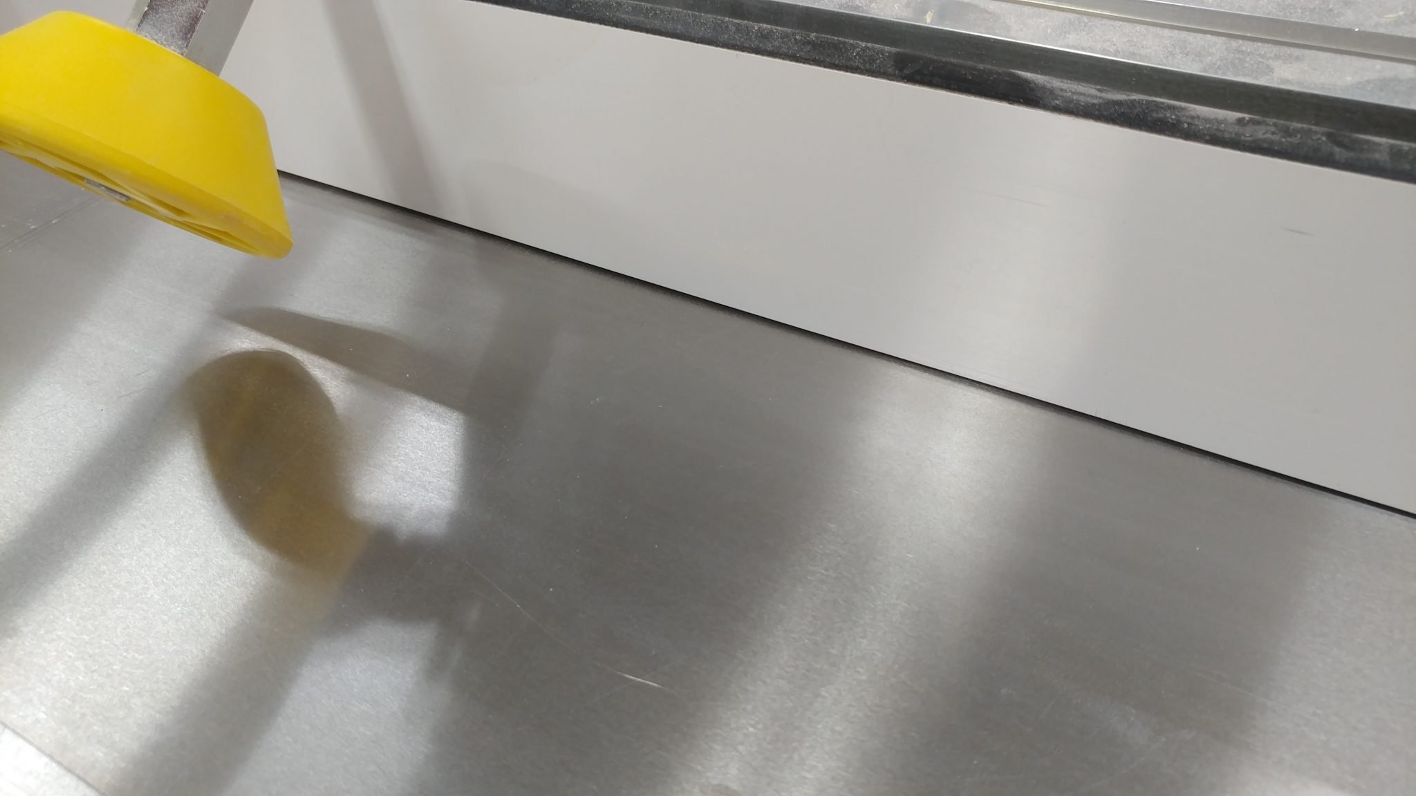
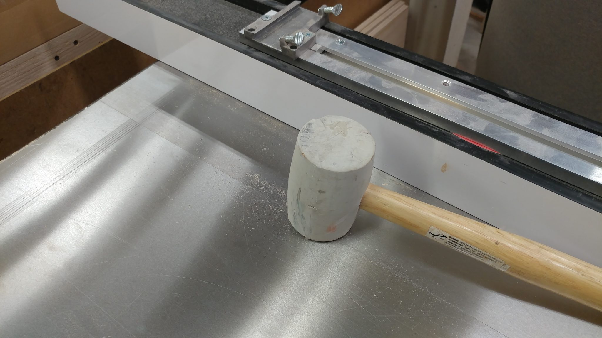
I used a rubber mallet to persuade the faceplate to rest closer to the top of the table.
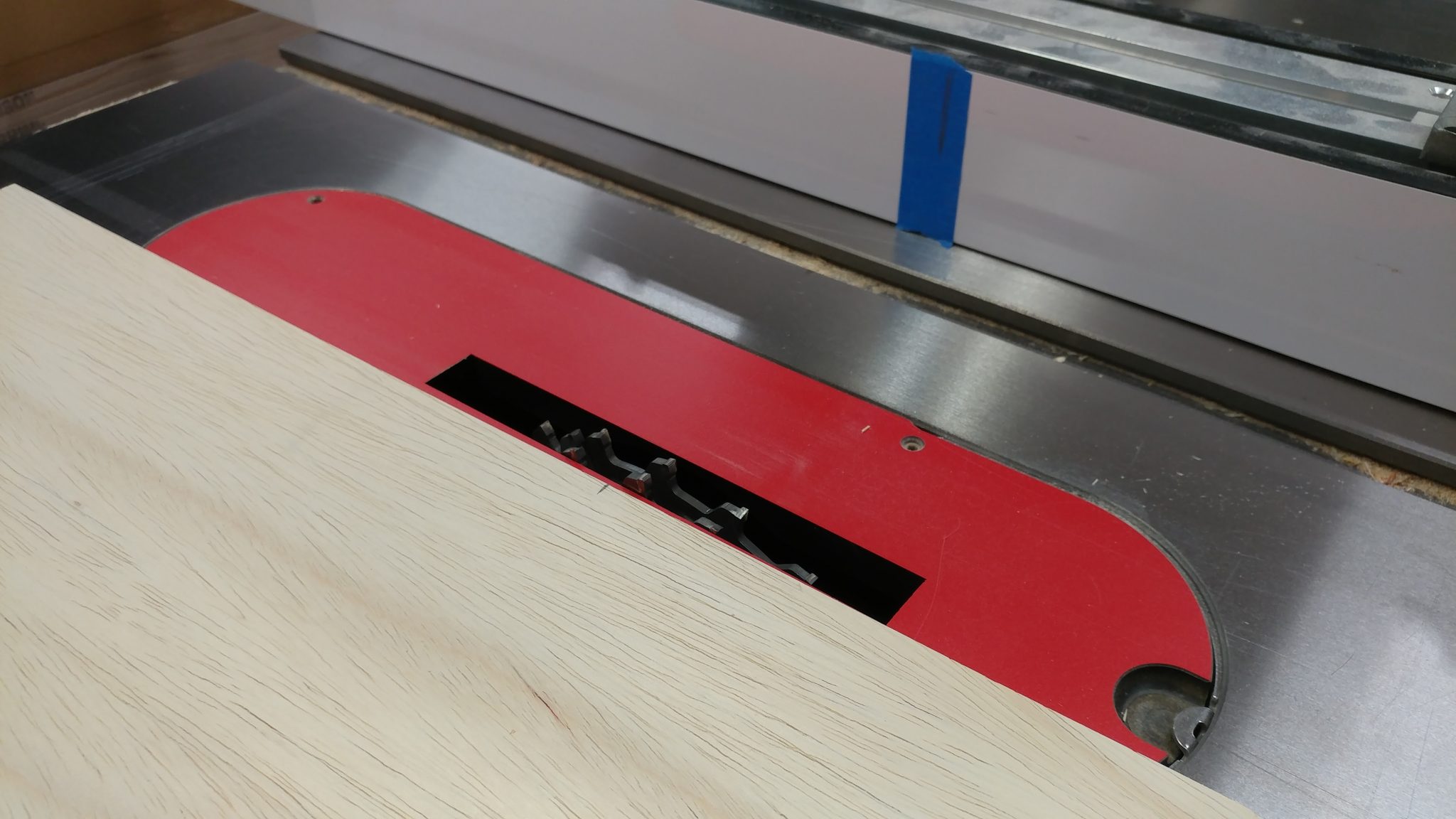
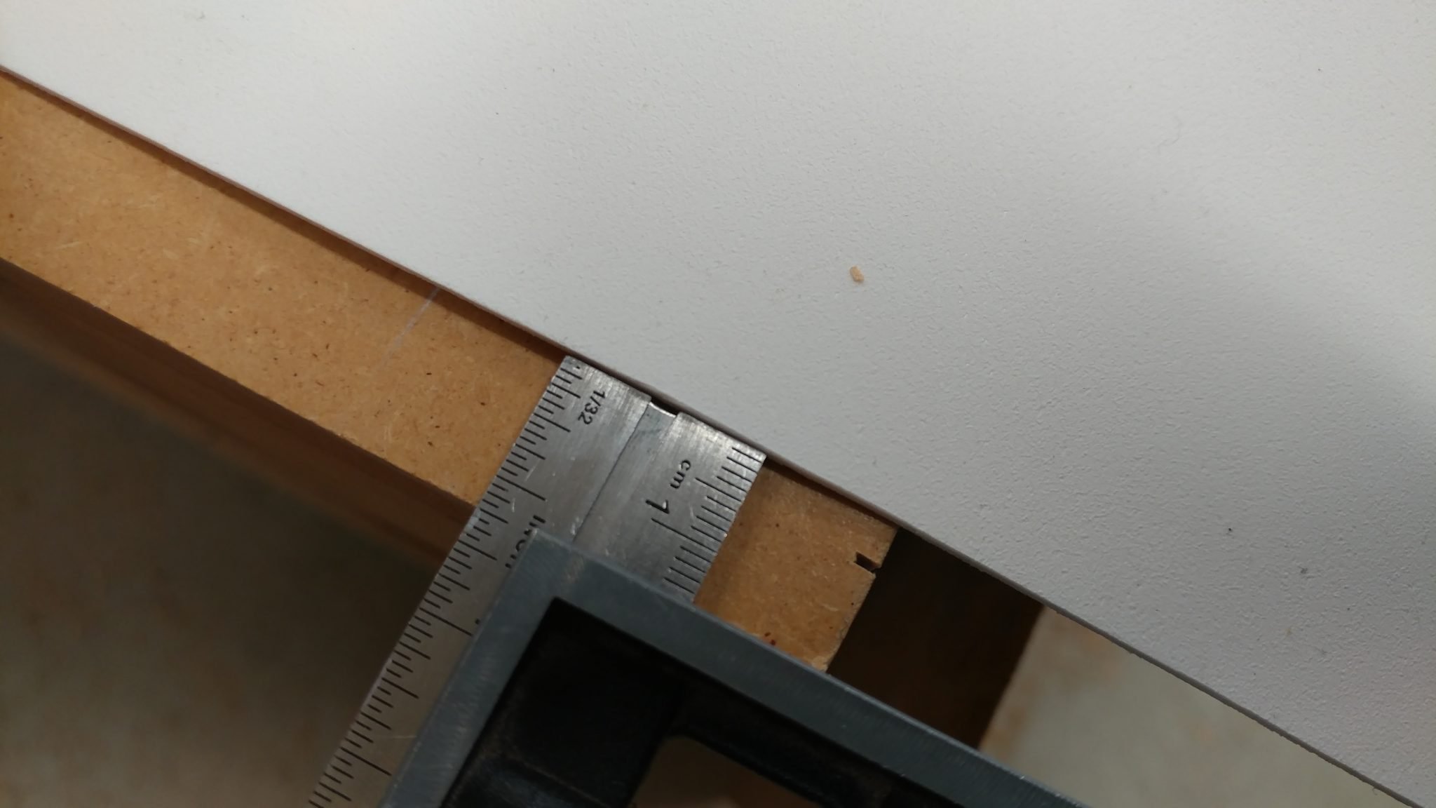
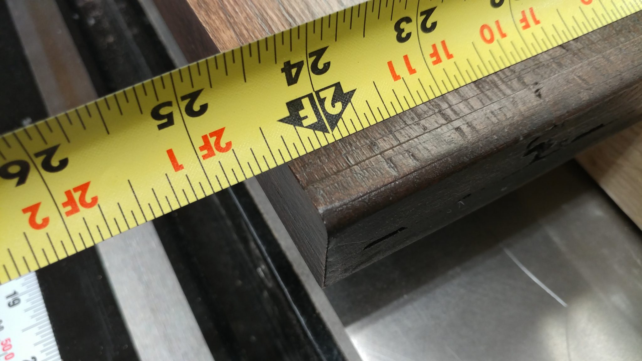
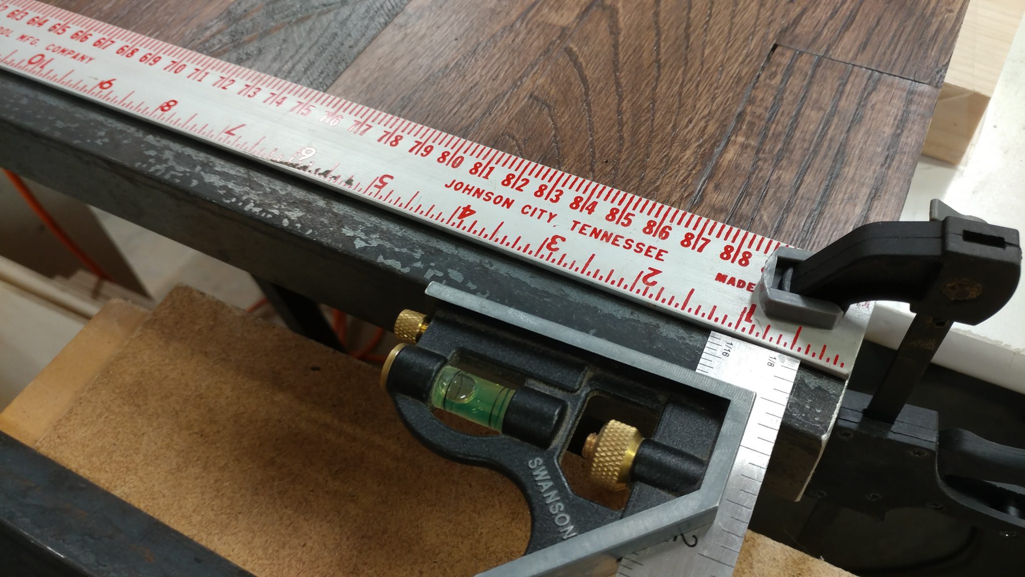
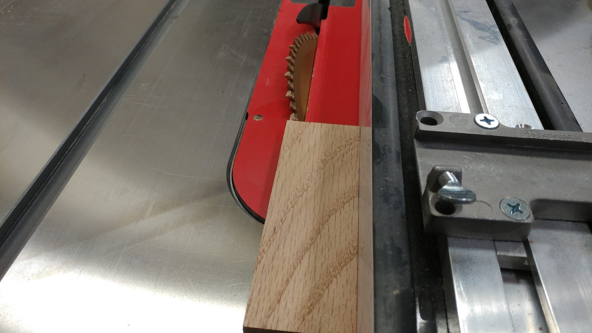
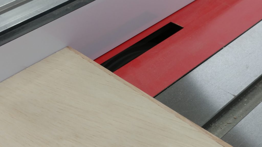
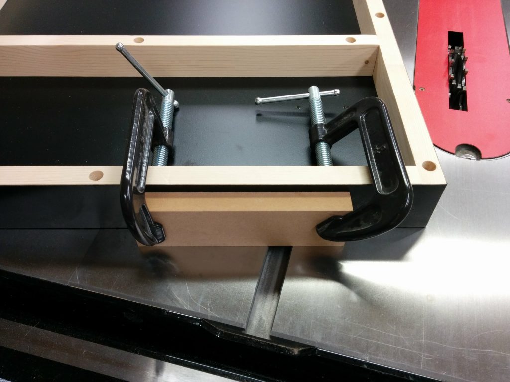
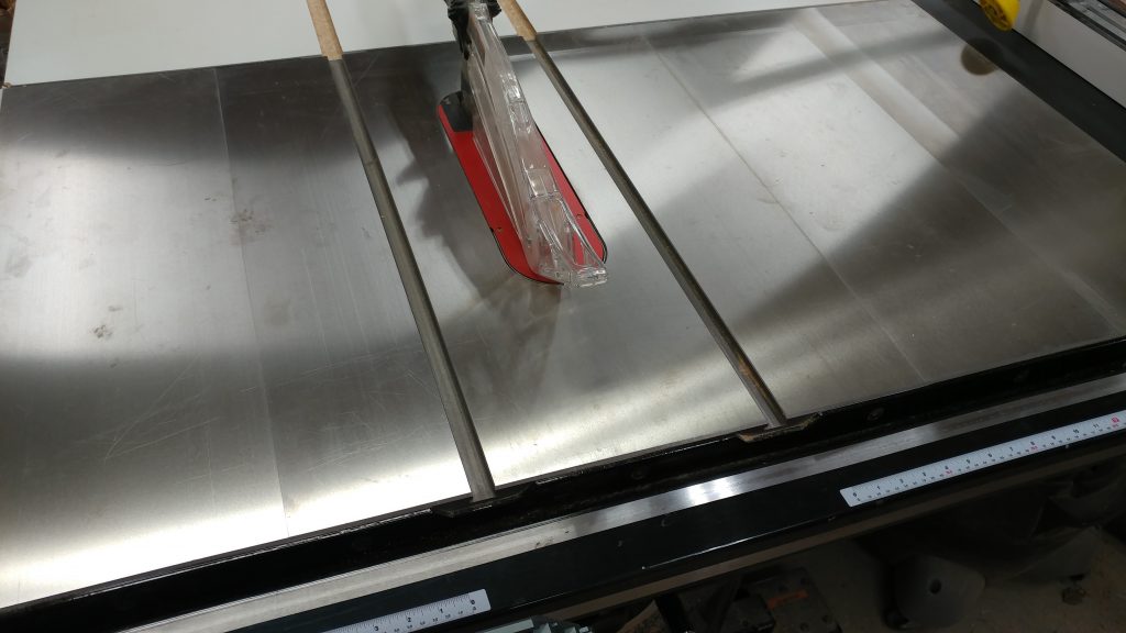
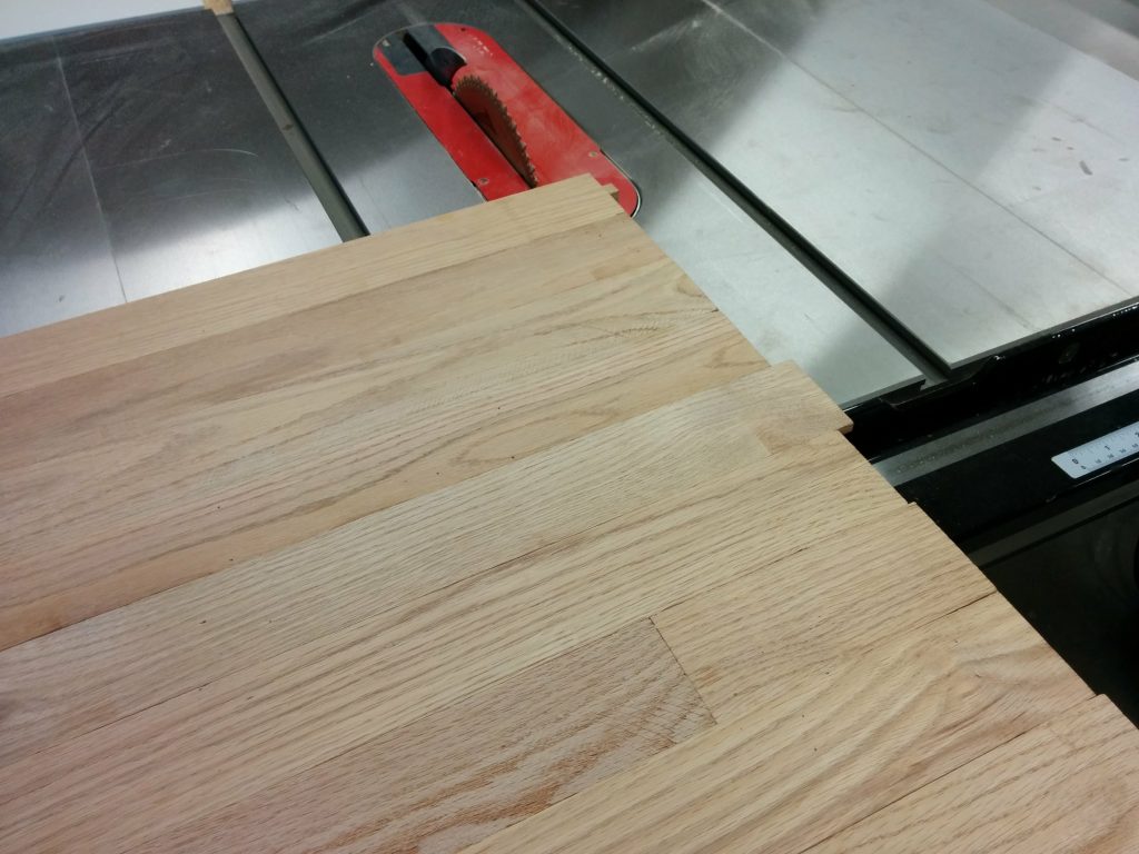
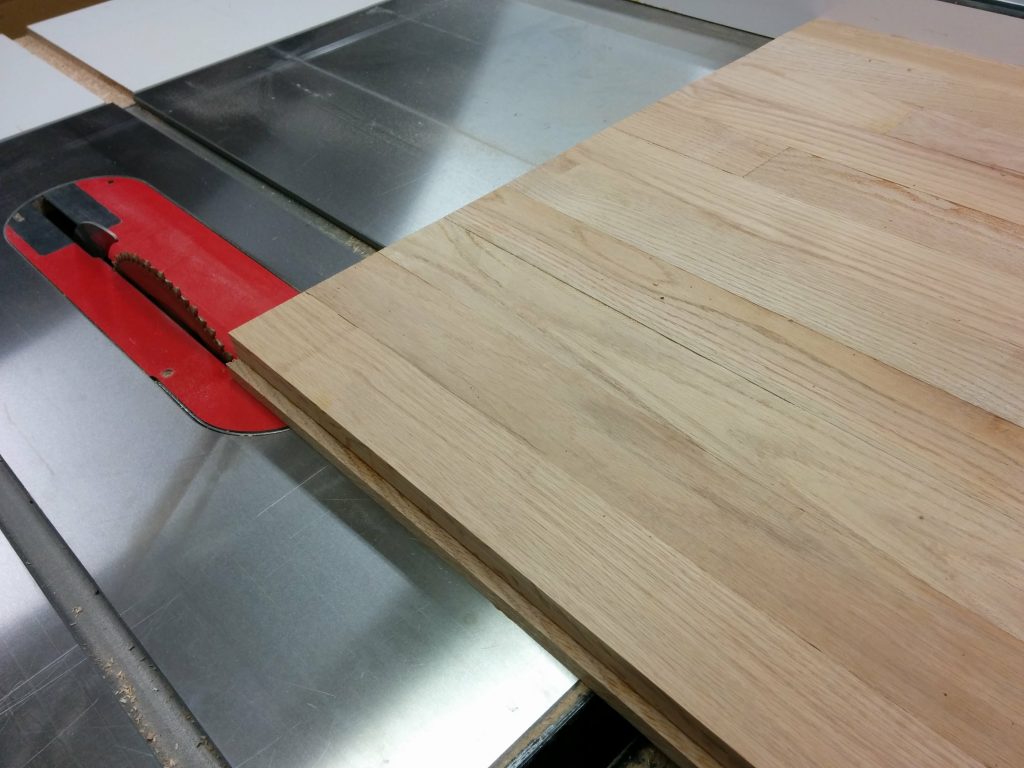
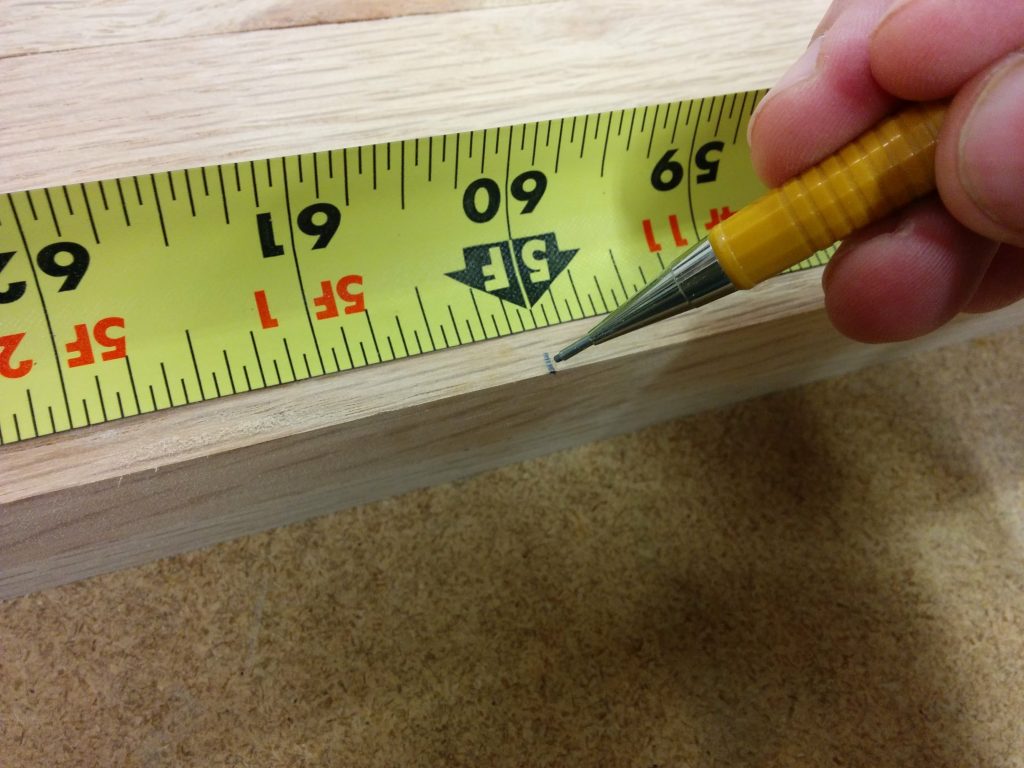
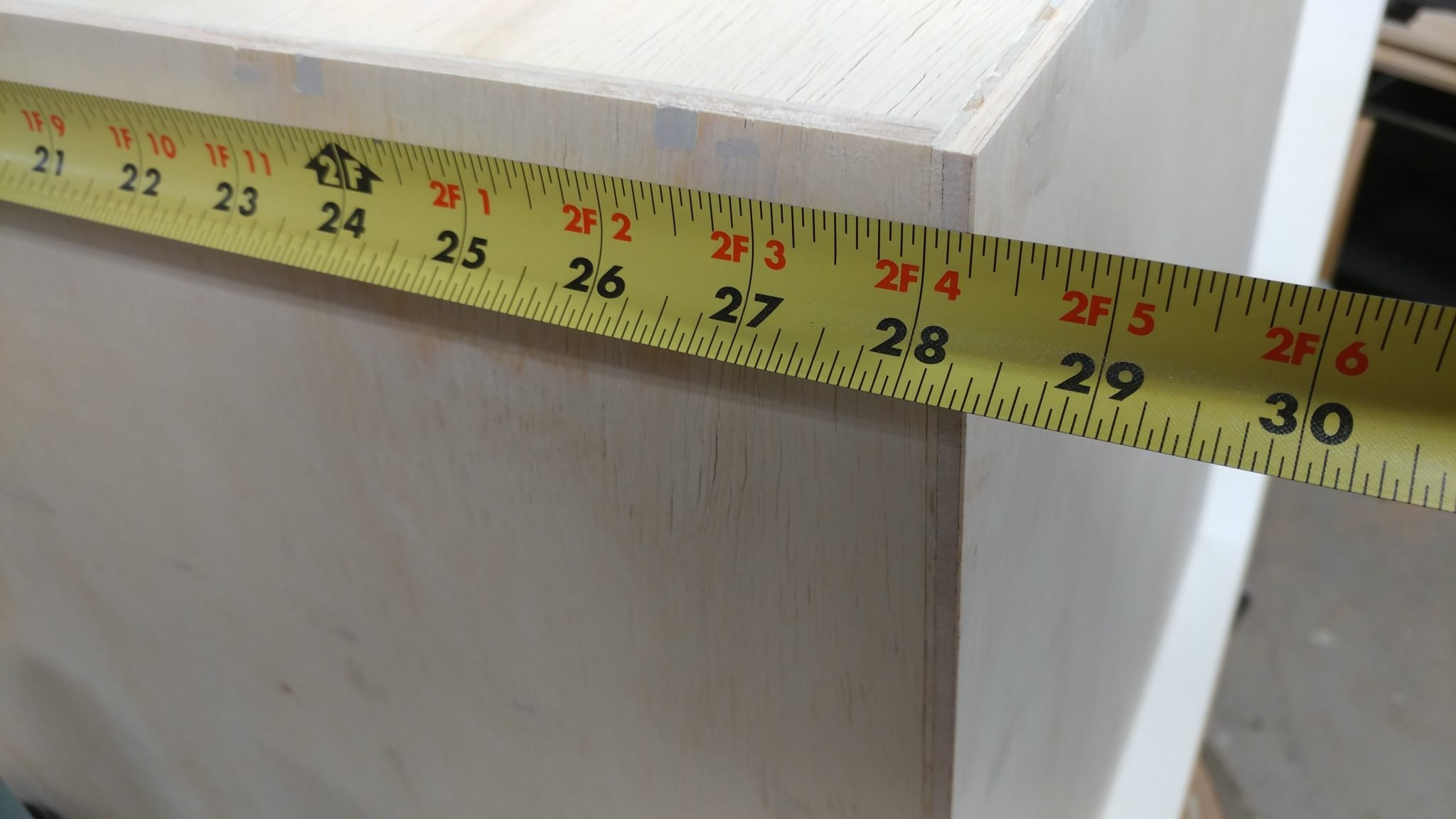
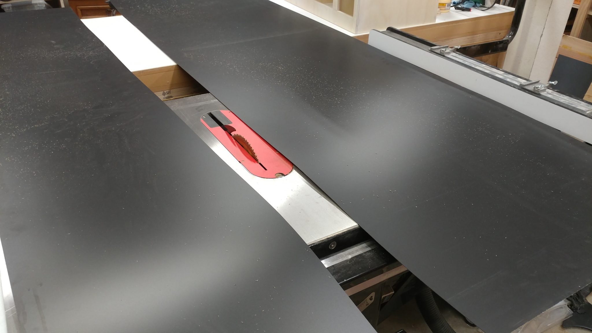
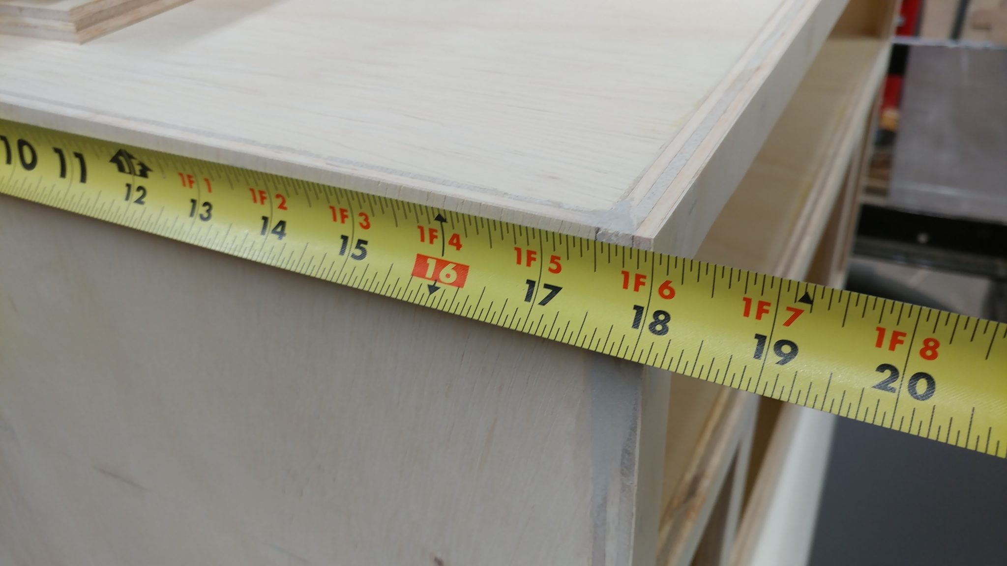
I’m going to start by ripping the laminate to the widest width that I’ll need, which is 28-1/4″. I actually ripped it to 29″ so I would have a little overhang.
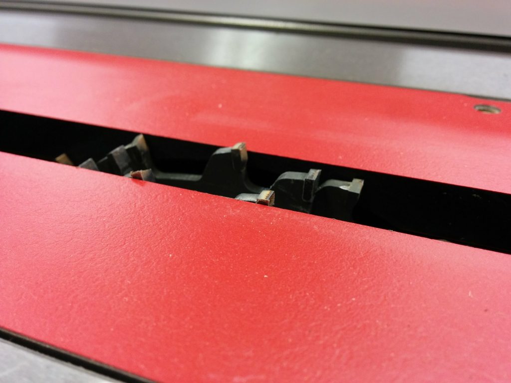
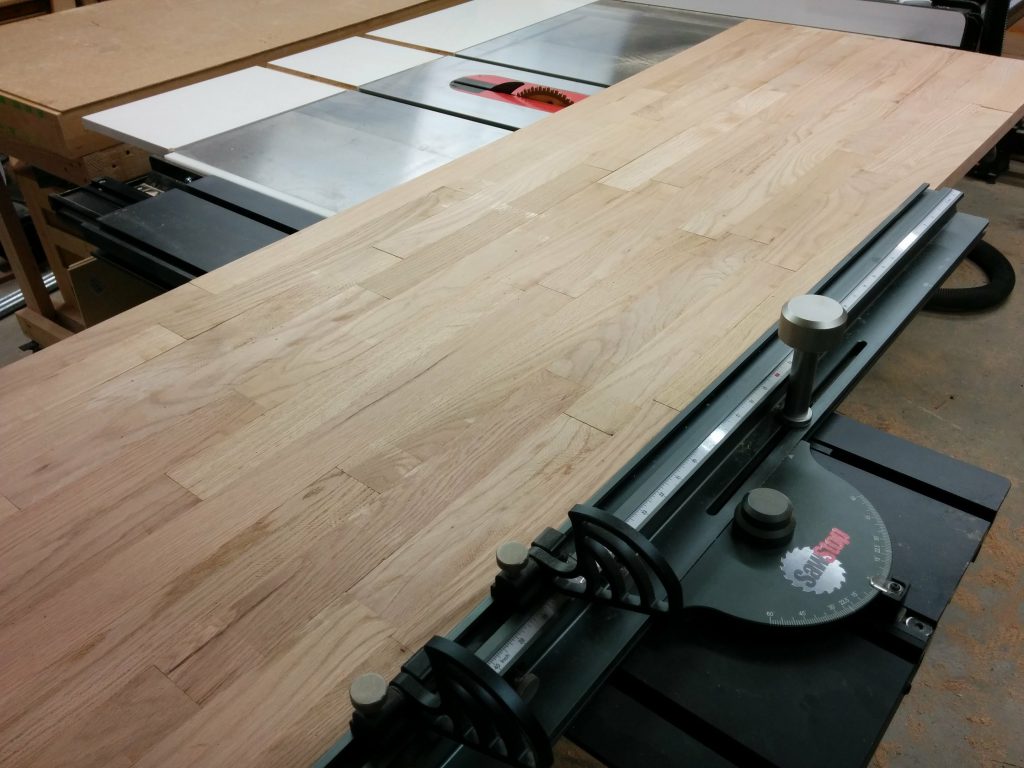
When cutting laminate, I like to use a SawStop 80-tooth Titanium blade. It gives a really smooth edge. Also, when cutting something as thin as laminate, I like to have the blade raised up above the material quite a bit more than usual since the material will try to climb up the blade otherwise.
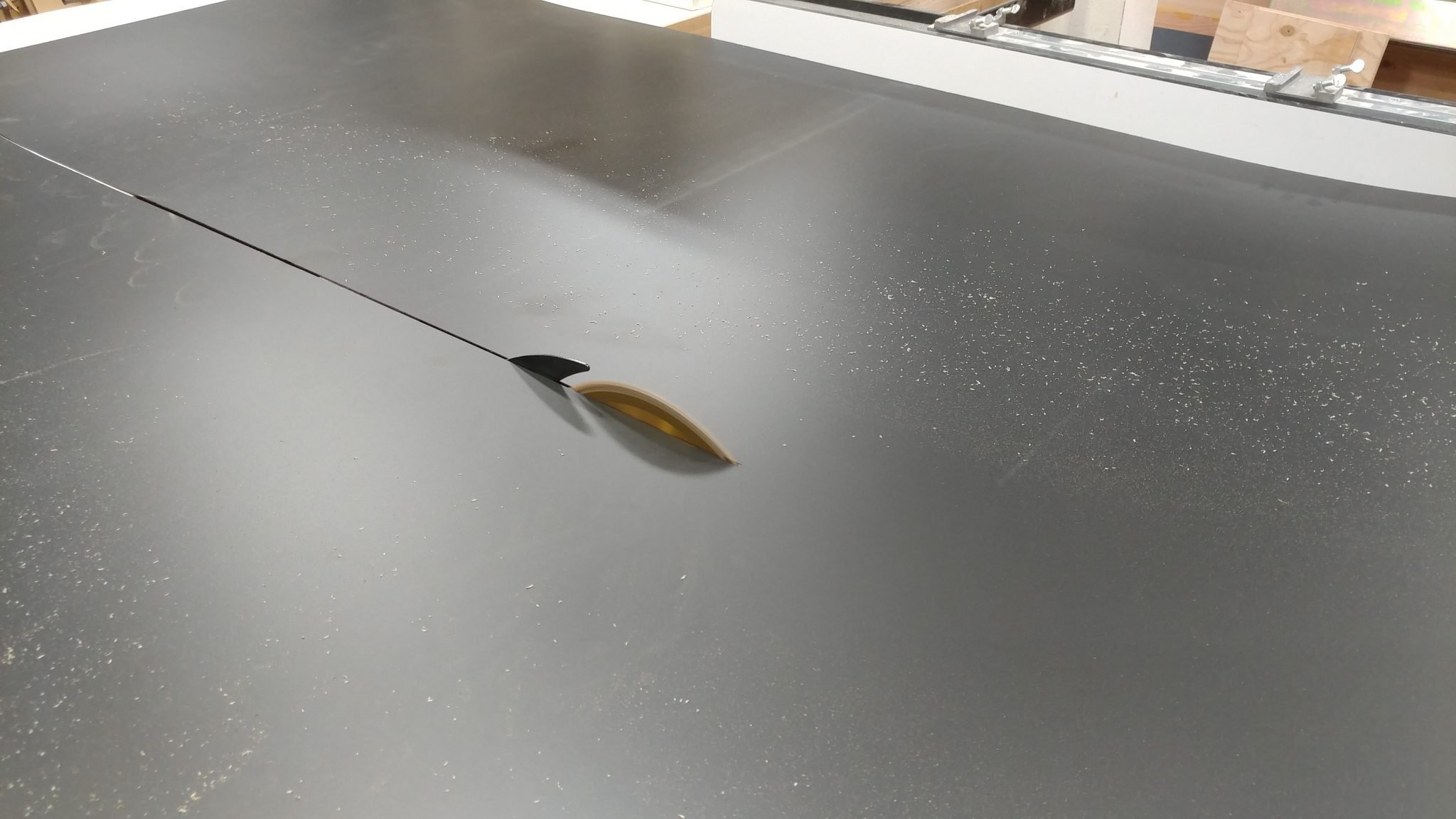
This was the most awkward cut.
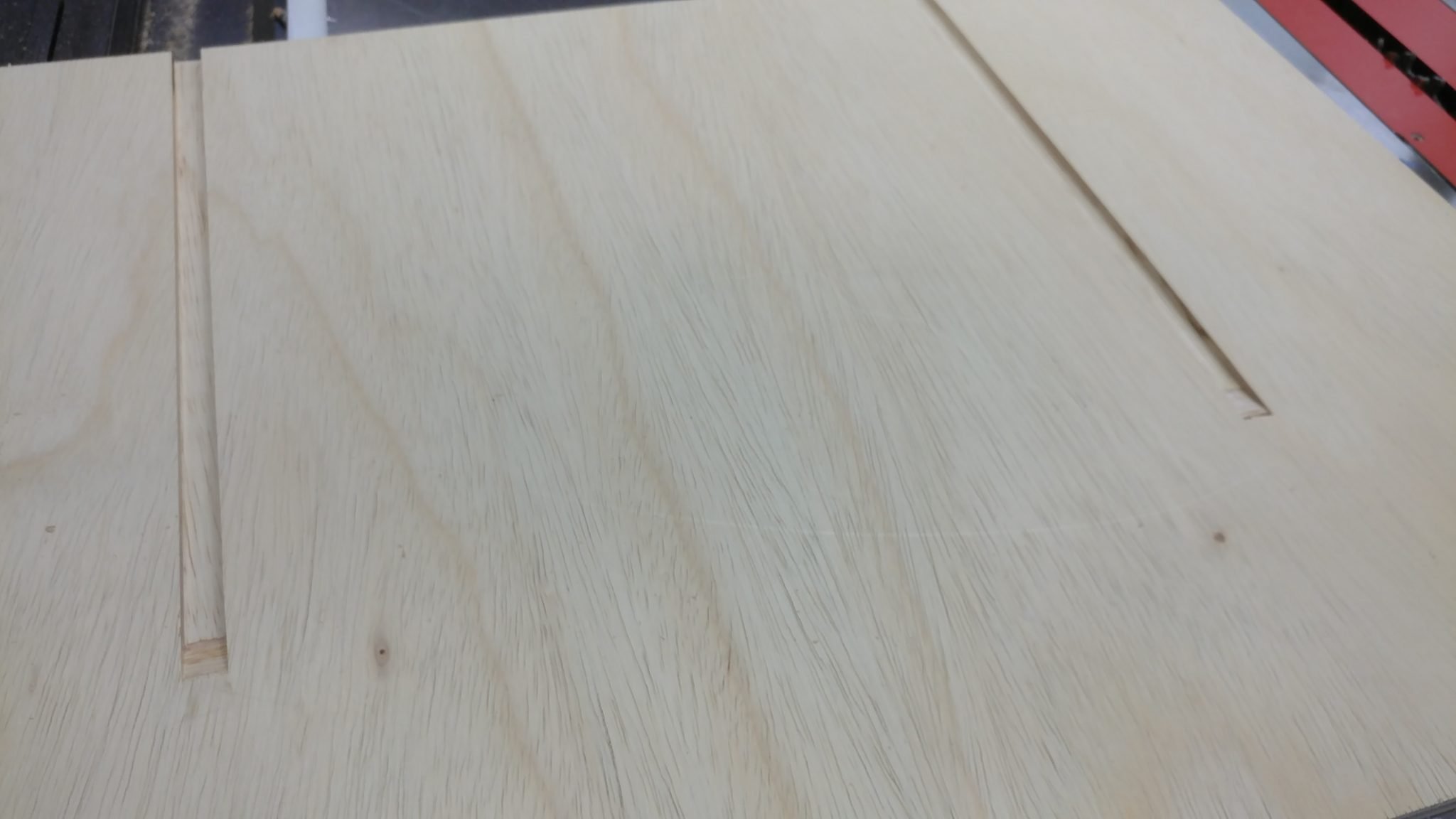
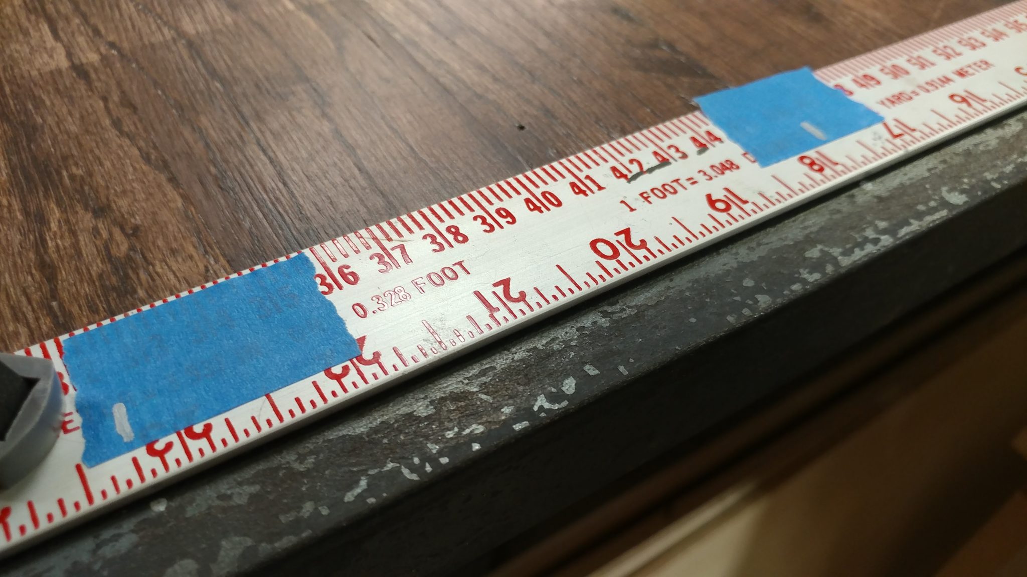
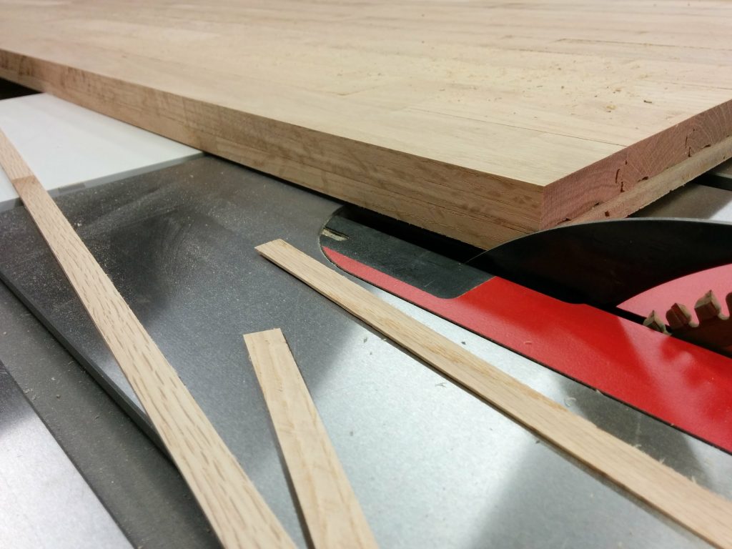
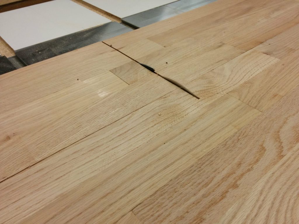
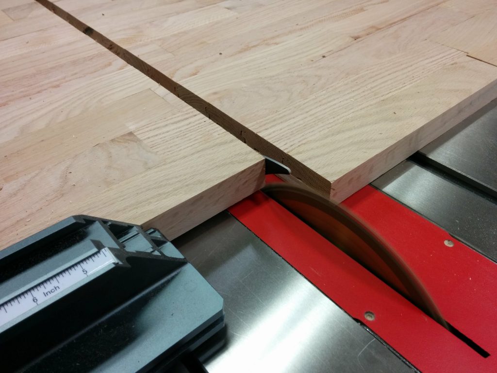
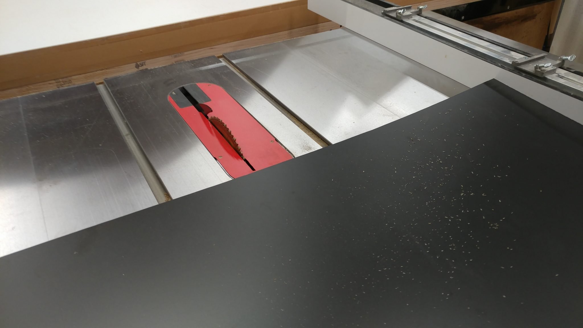
Then I cut two pieces that will cover the front and back, which are 19″ high. I decided to cut the pieces down to 20″ each.
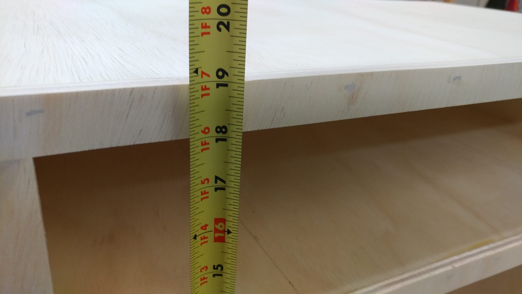
This can be a bit awkward too but it was still easier than wrestling with the full sheet of laminate.
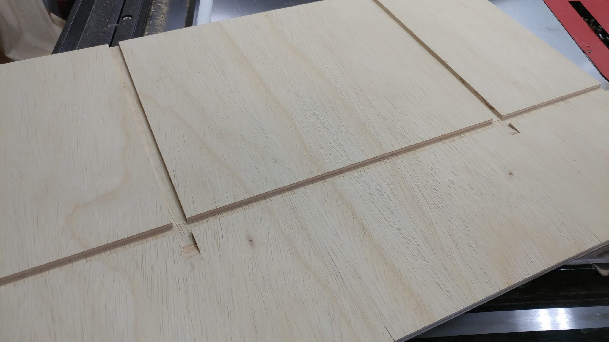
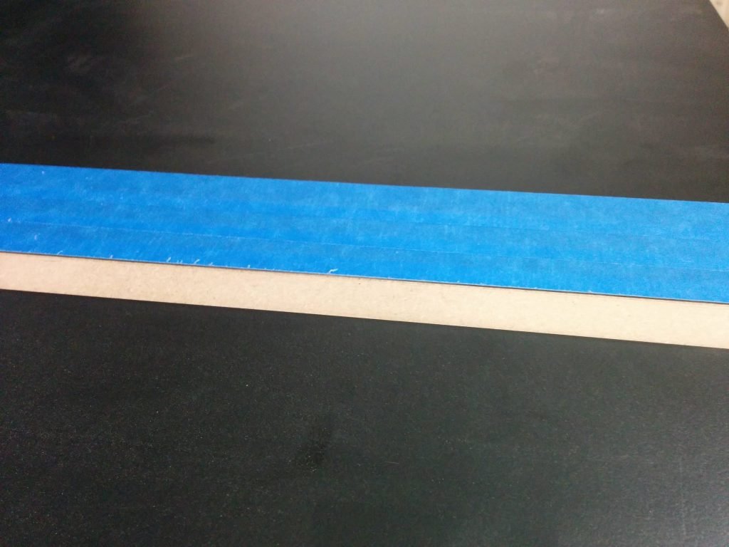
The two pieces of laminate are cut down.
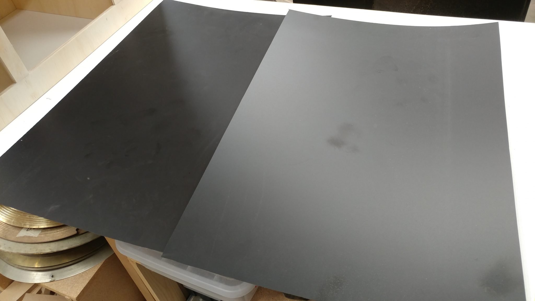
I then measured the sides and cut pieces for them.
Applying the laminate
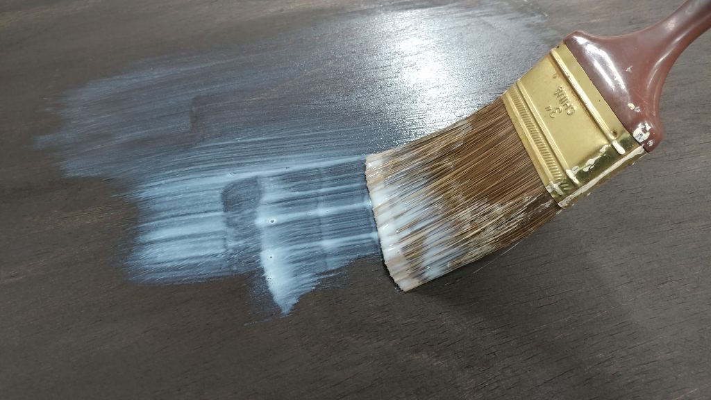
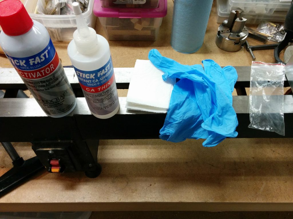
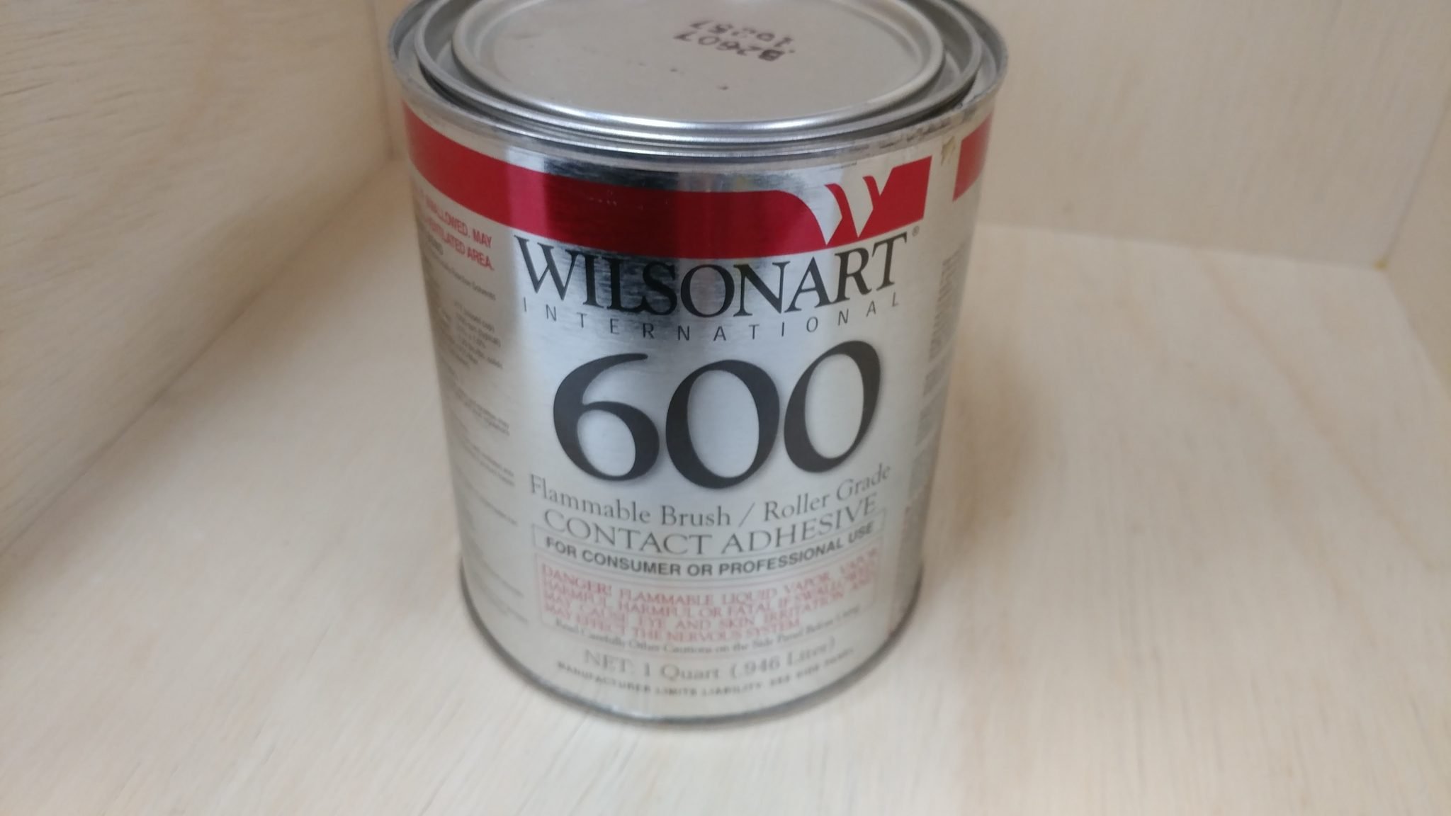
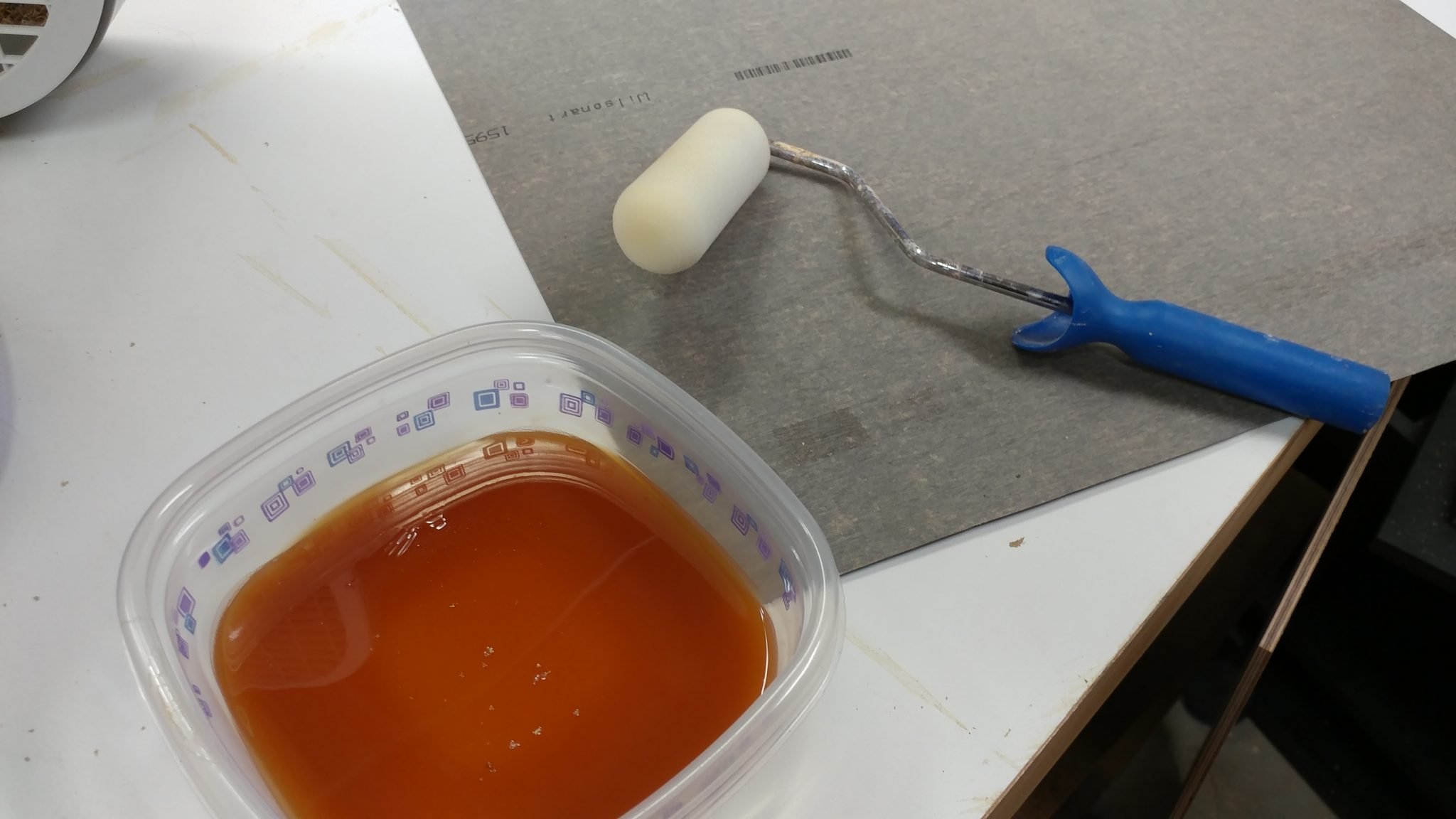
I’m using Wilsonart International 600 contact adhesive.
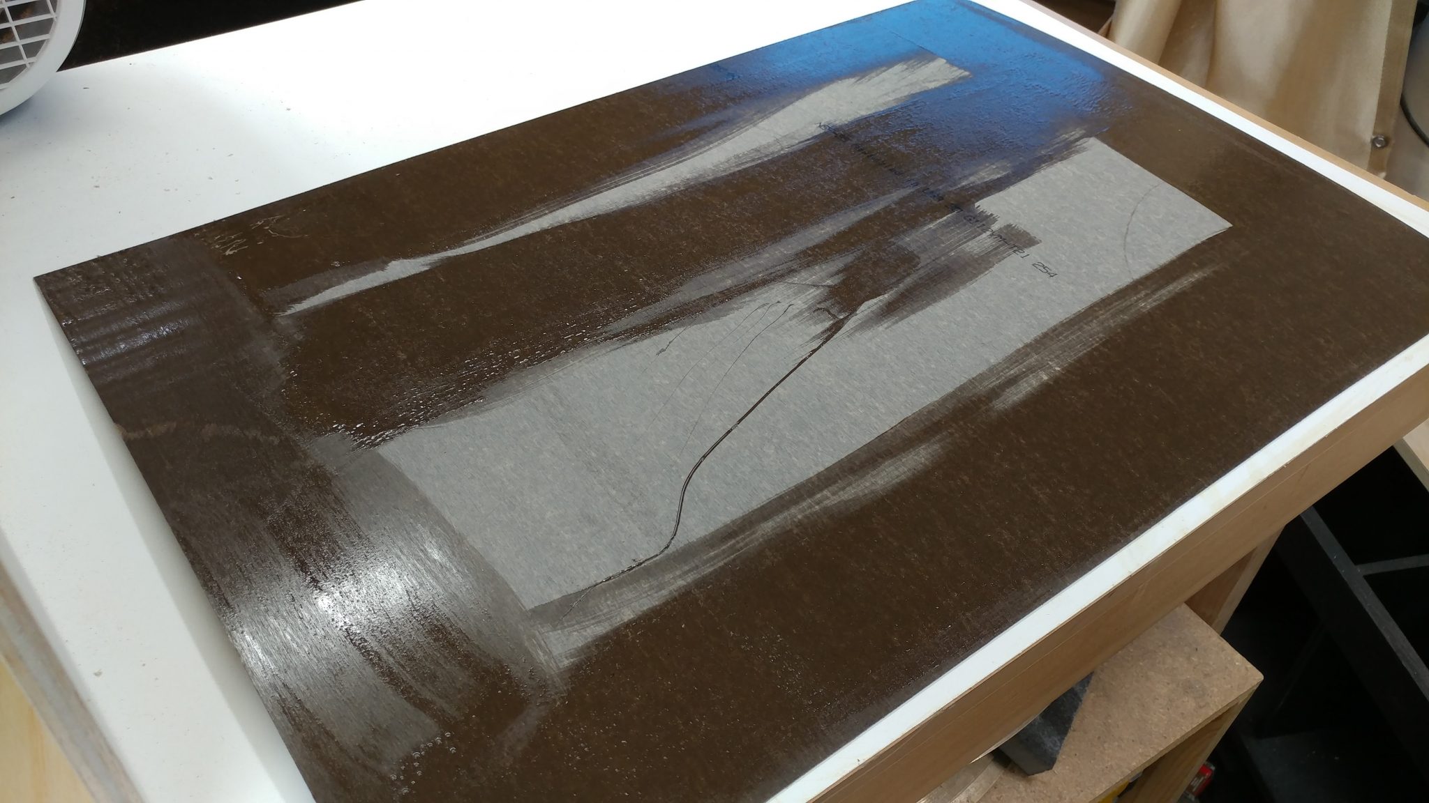
I used a foam roller to apply a coat of contact cement to the front surface of the carcase.
I then applied contact cement to the back of the laminate. Here I am applying to just the areas that will be contacting the wood. Right after I took this photo I realised that I forgot to apply some where the laminate will touch the two vertical walls so I added some there.
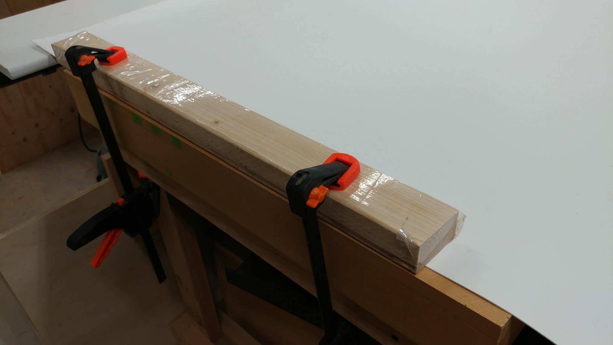
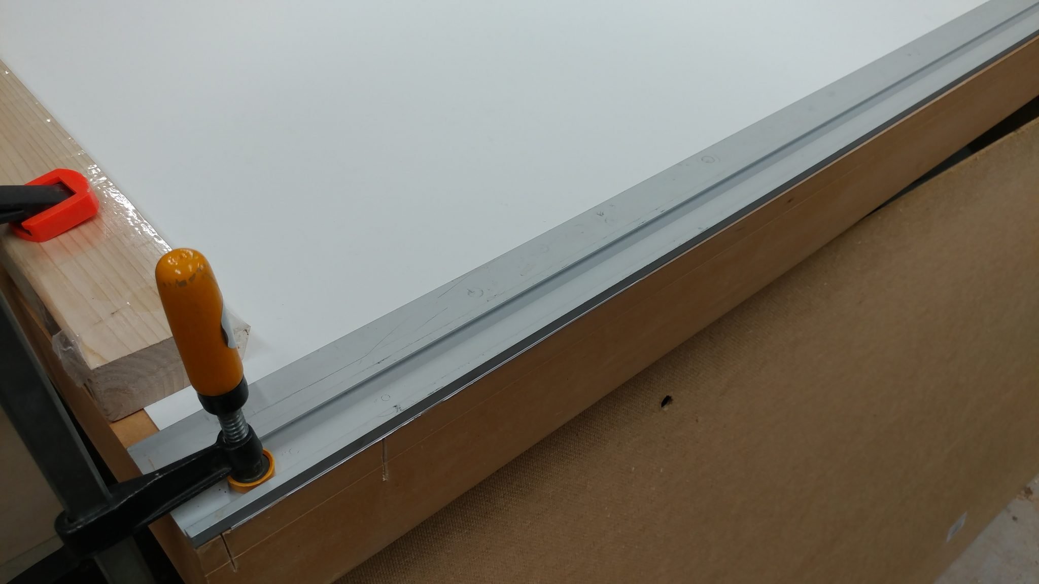
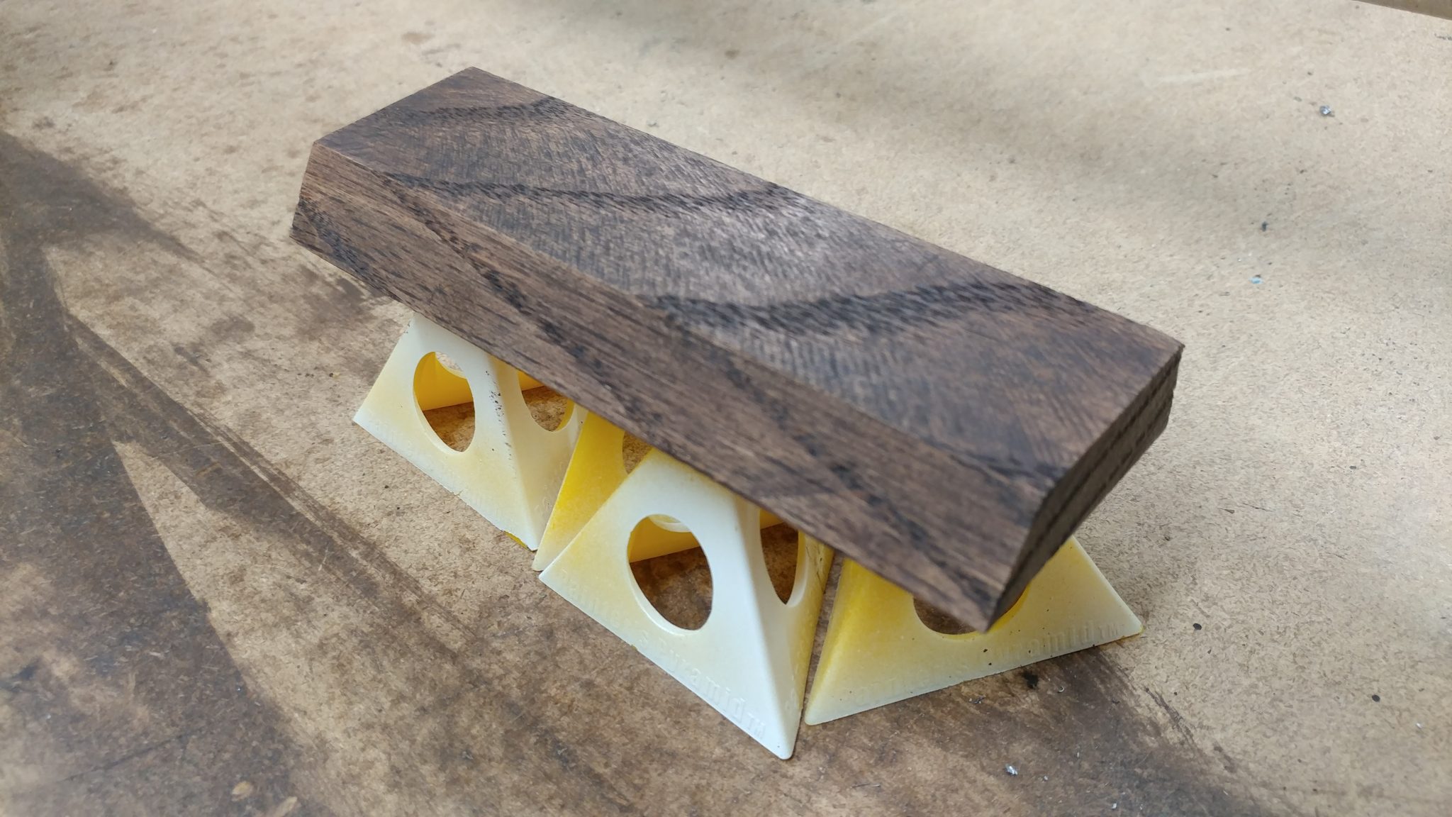
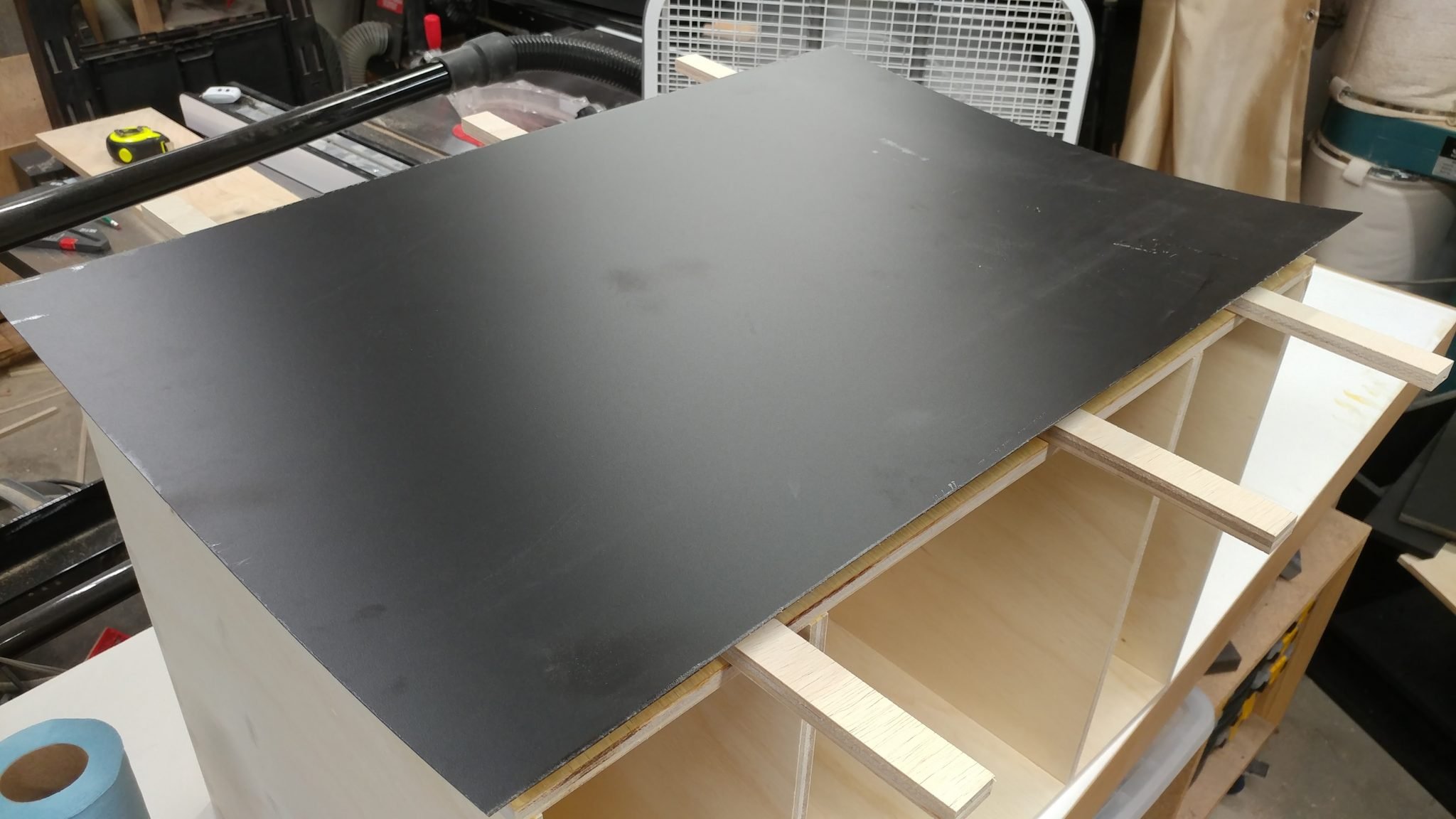
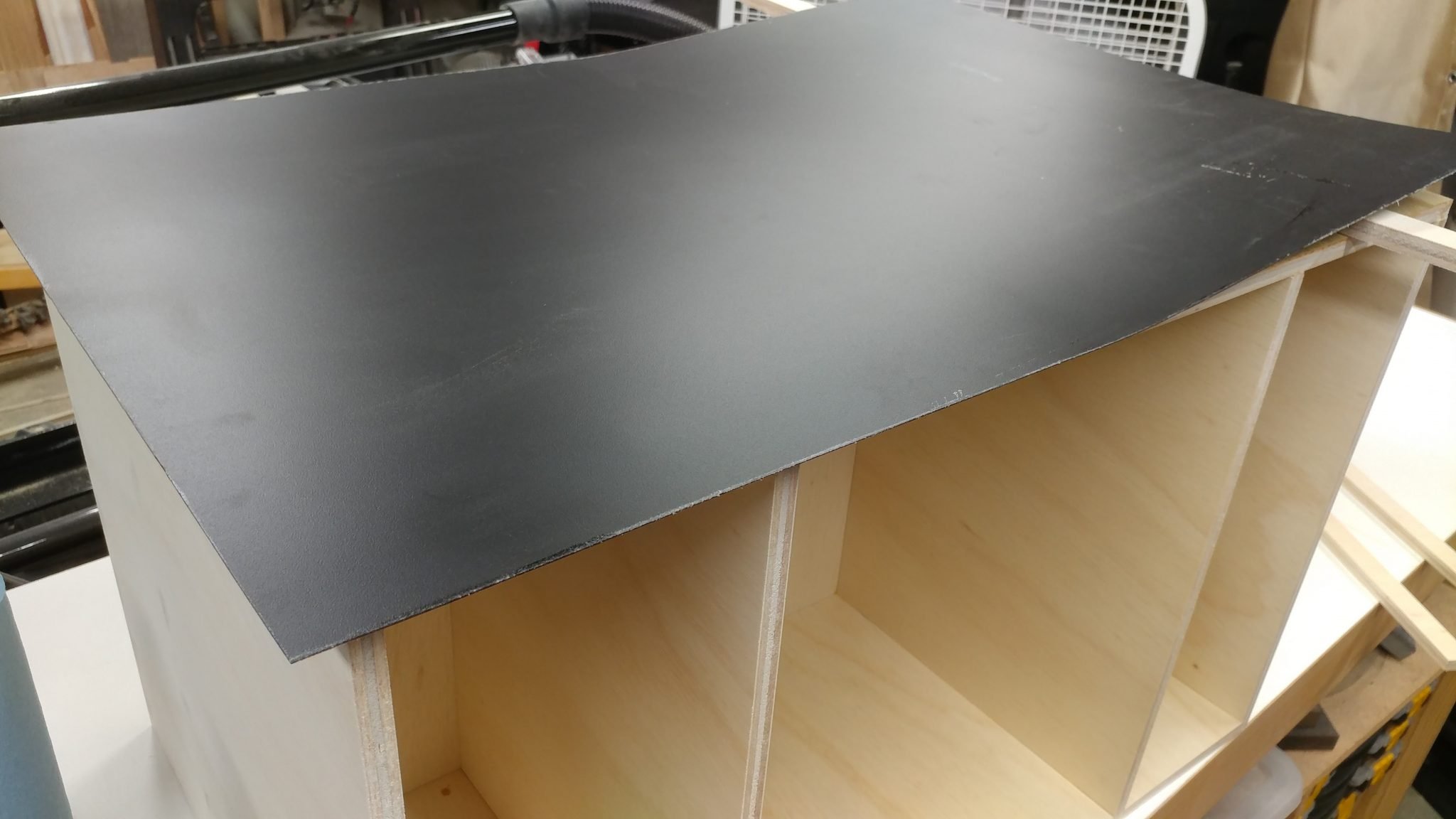
The contact cement sets up pretty quickly. You want to wait till it isn’t really sticky anymore. The surface should be just a bit tacky. Once the two pieces touch each other, they’re pretty much staying like that. In order to attach the laminate correctly, lay some scrap strips of wood on the work surface…
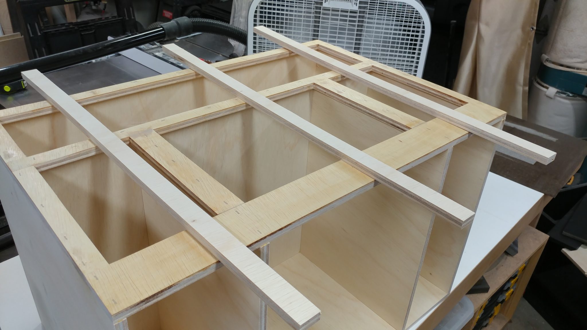
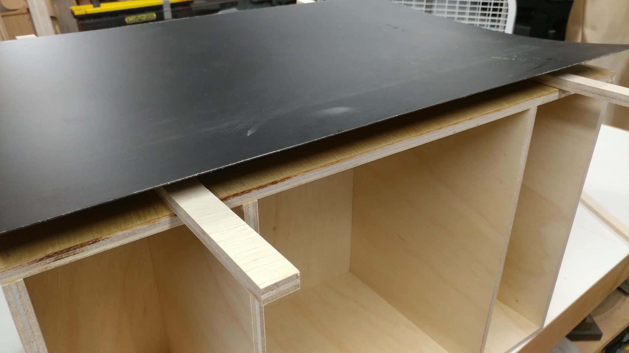
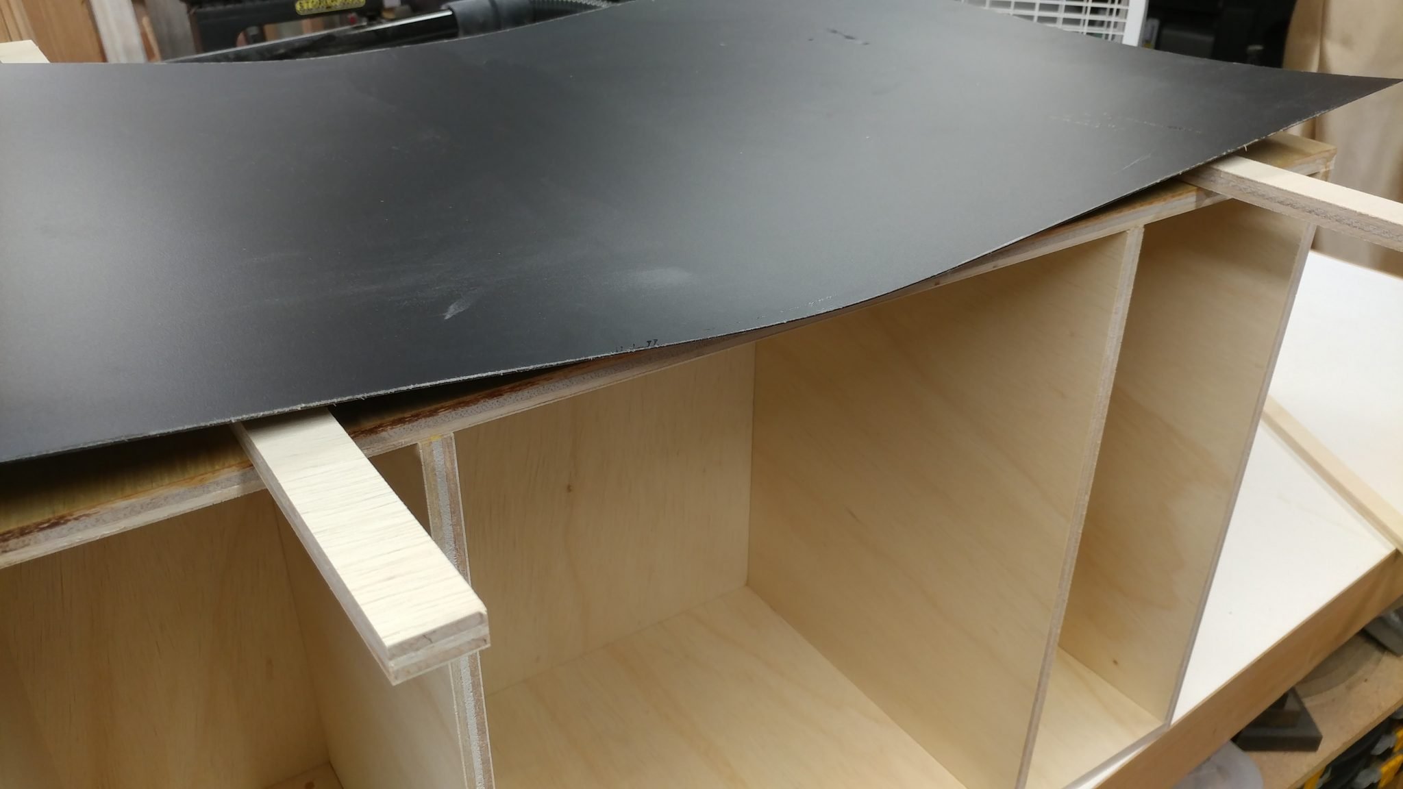
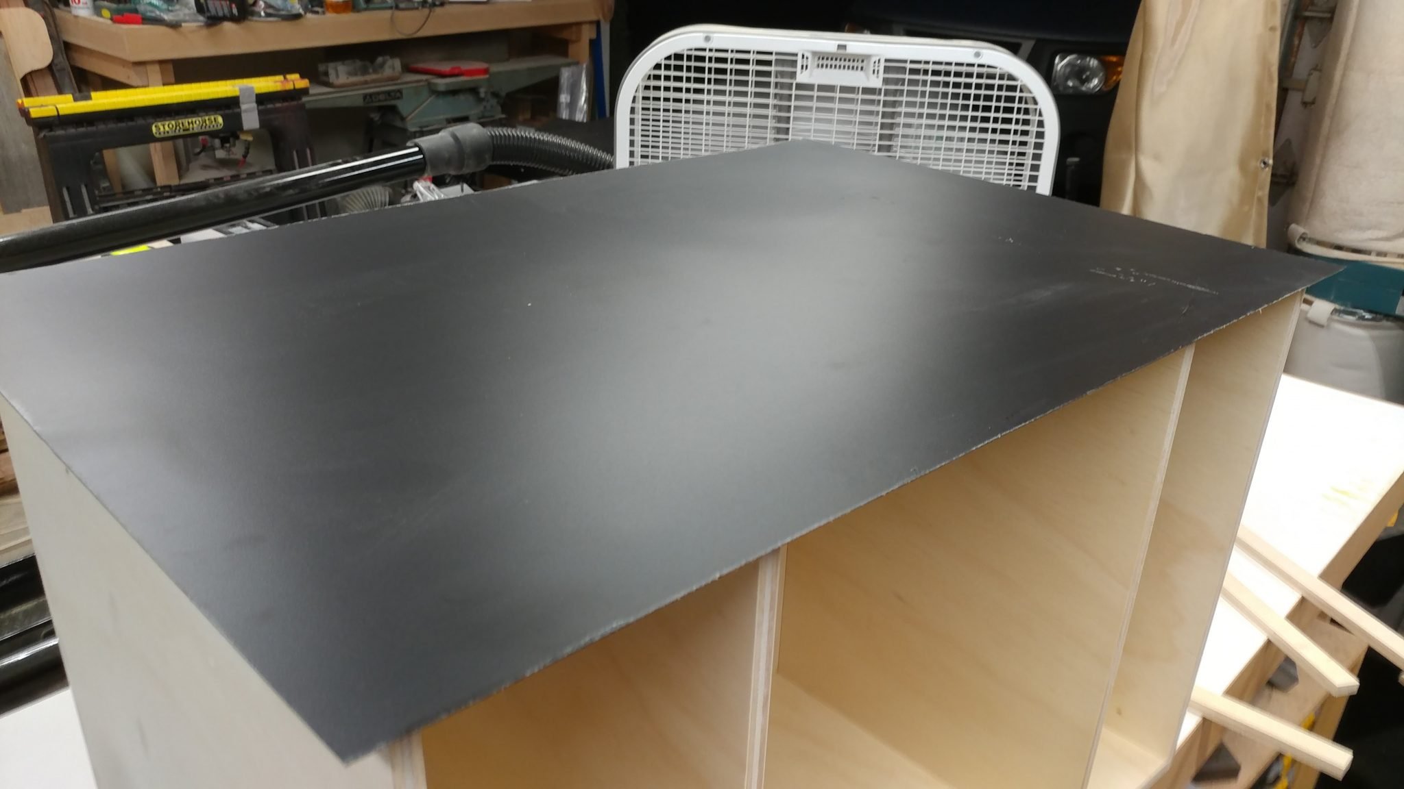
…then lay the laminate, sticky-side-down, on top of the strips of wood. Use this opportunity to position it correctly.
I like to work from the center-out so I first remove the inner-most wood strip(s).
Press down firmly right in the center and work your way to the front and back edges.
Then remove one of the adjacent strips and press the laminate down working your way from the middle to the outside edge.
Then do the same thing for the opposite end of the laminate.
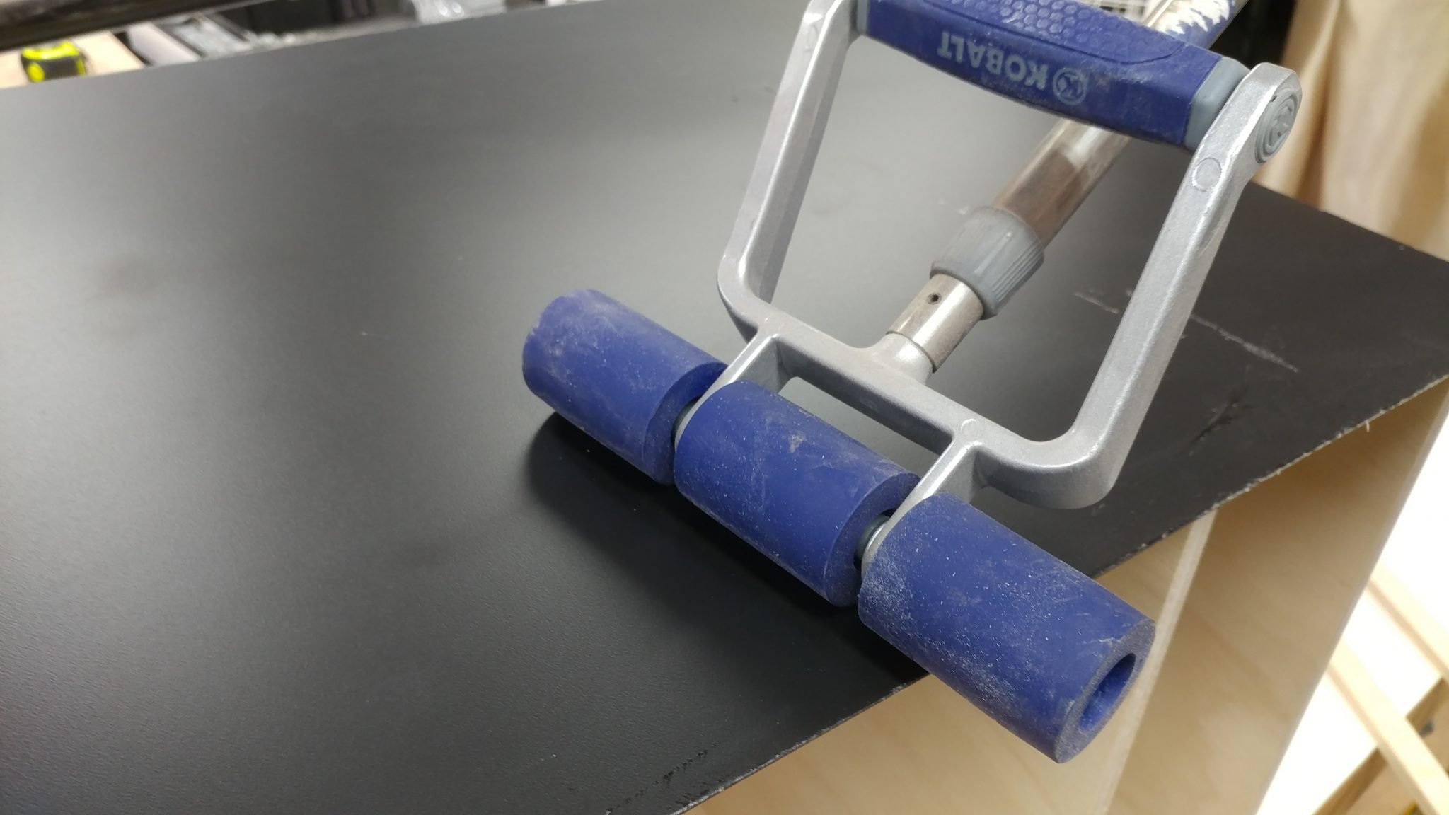
You can use a laminate roller to make sure that there aren’t any air bubbles. Again, work your way from the center to the edges.
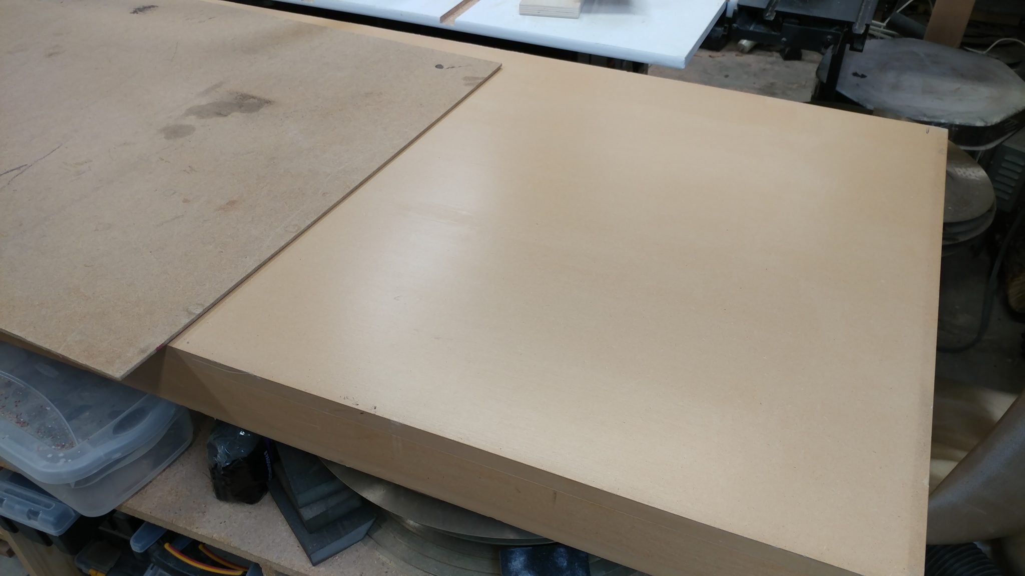
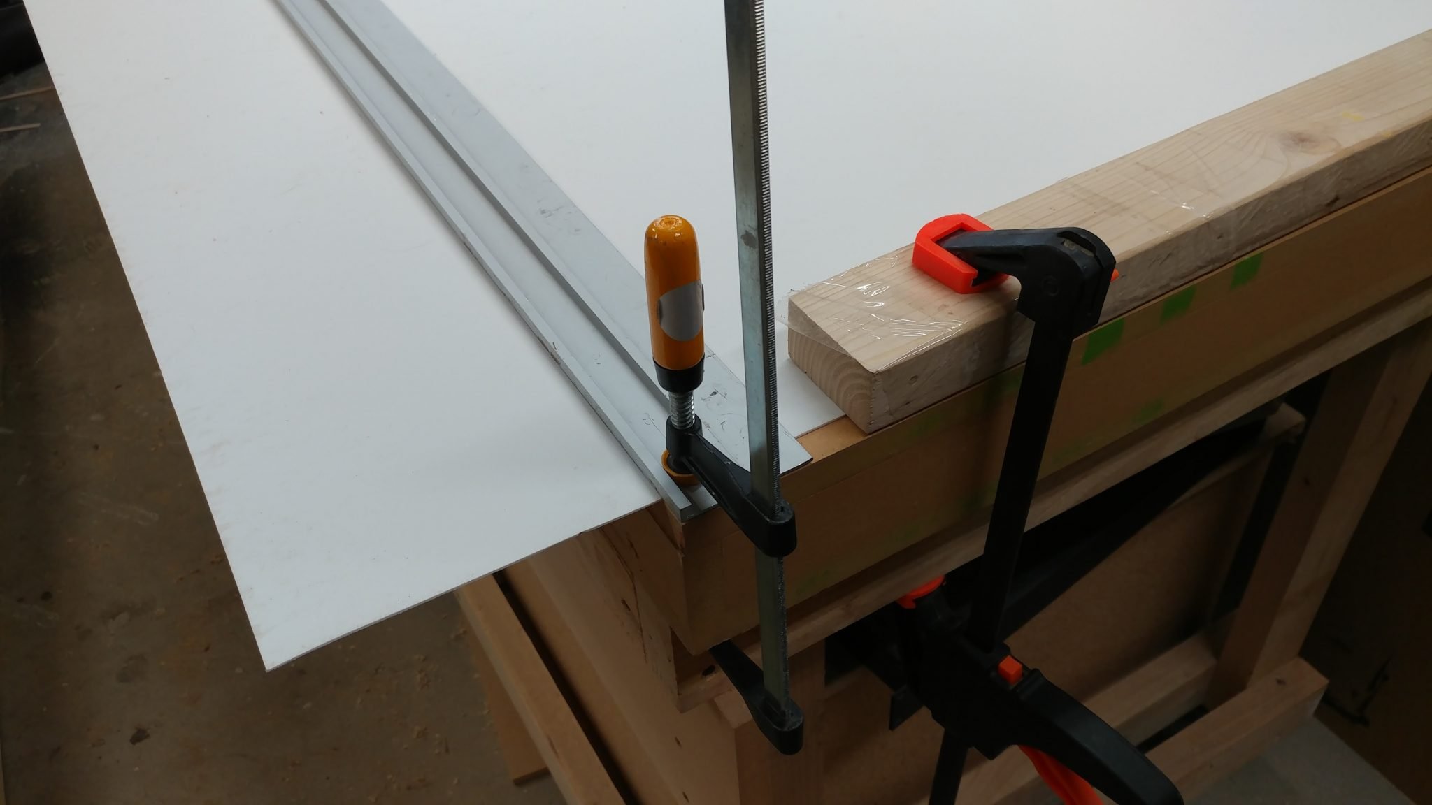
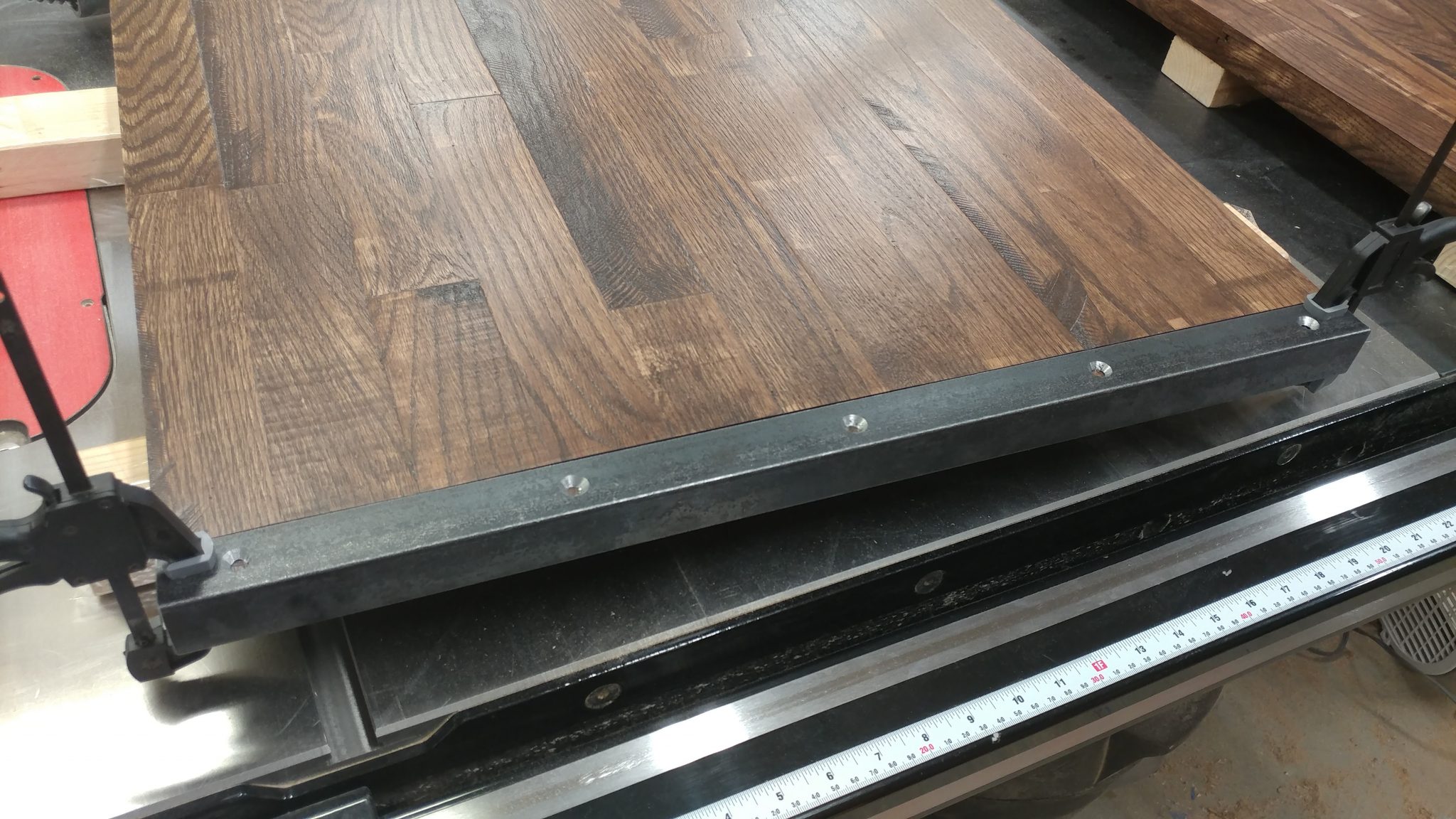
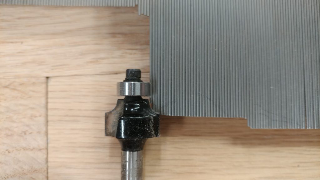
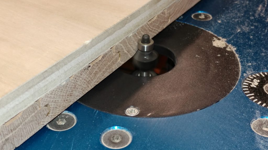
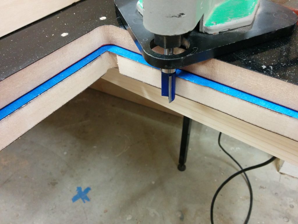
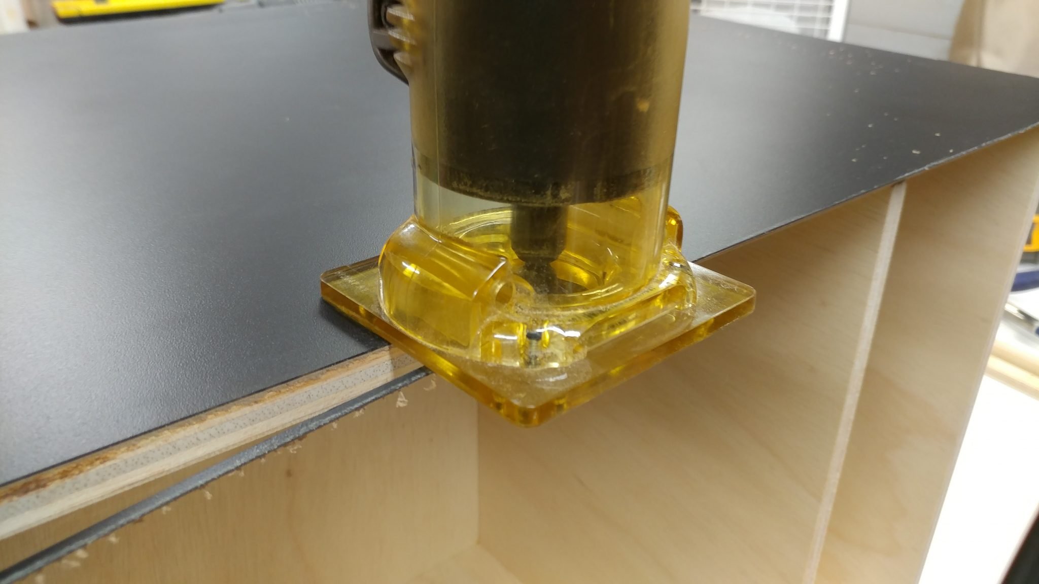
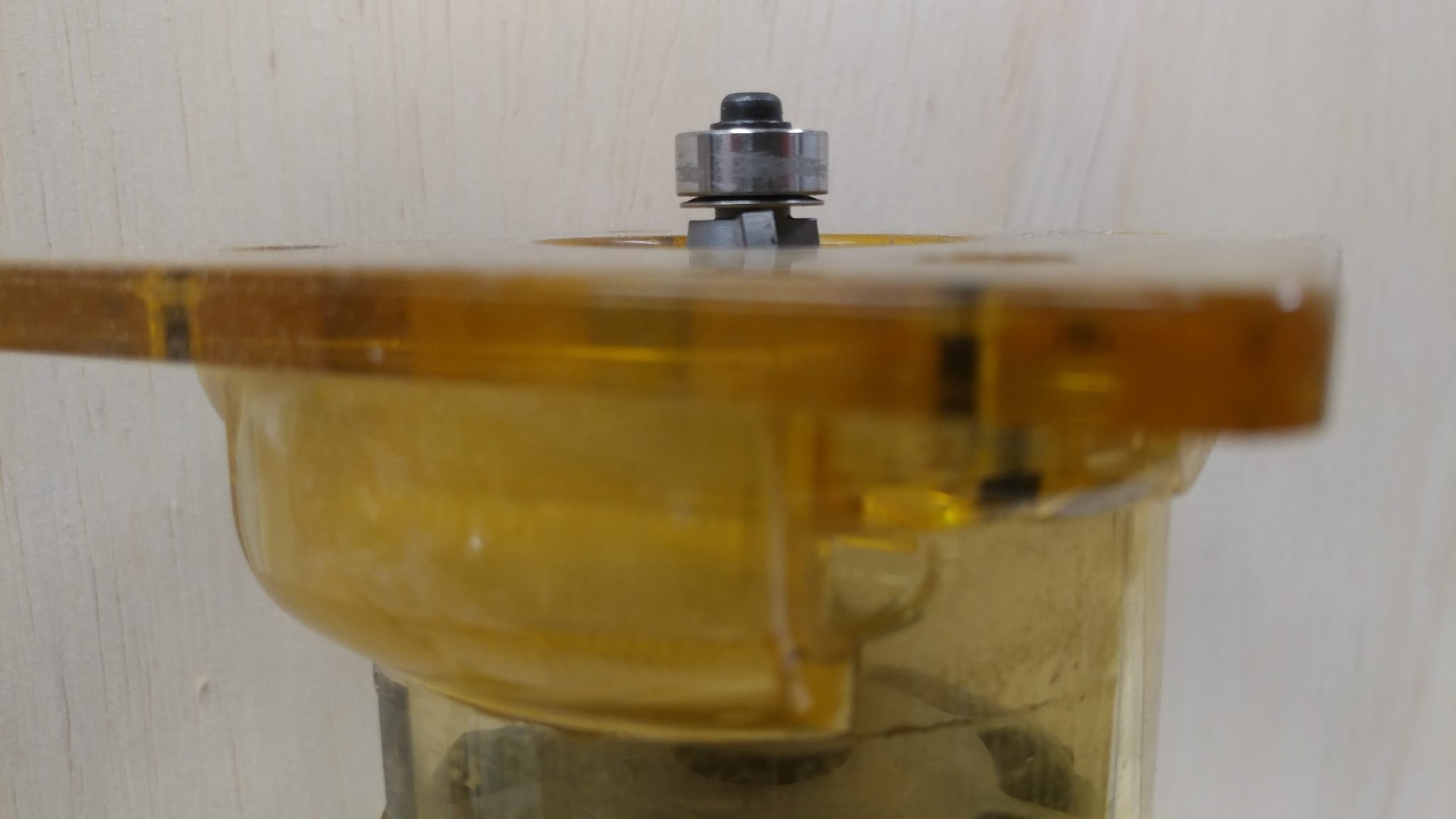
To trim the laminate flush with the cabinet, use a router with a straight pattern bit.
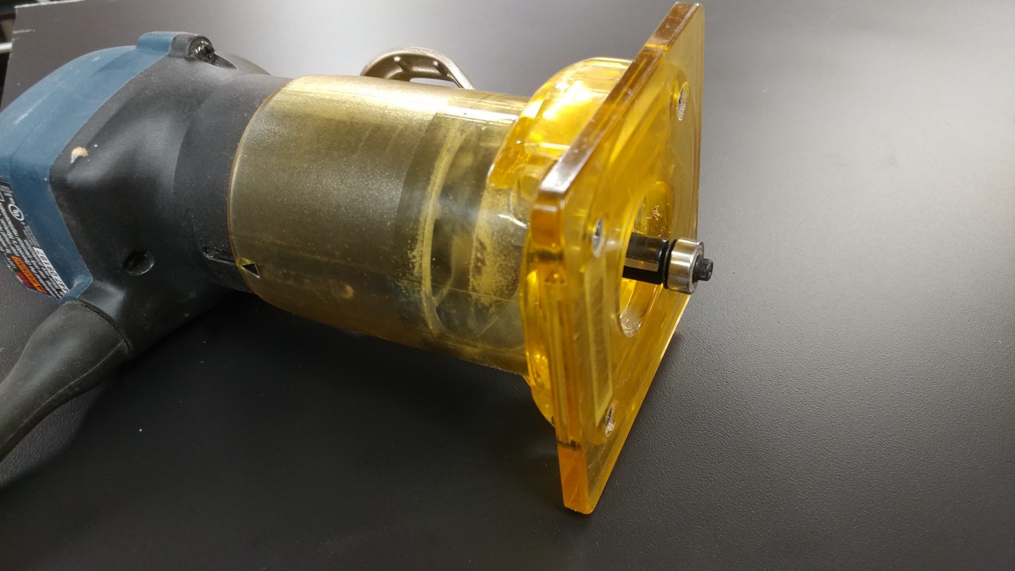
Position the router bit so the bearing will ride along the edge of the work surface.
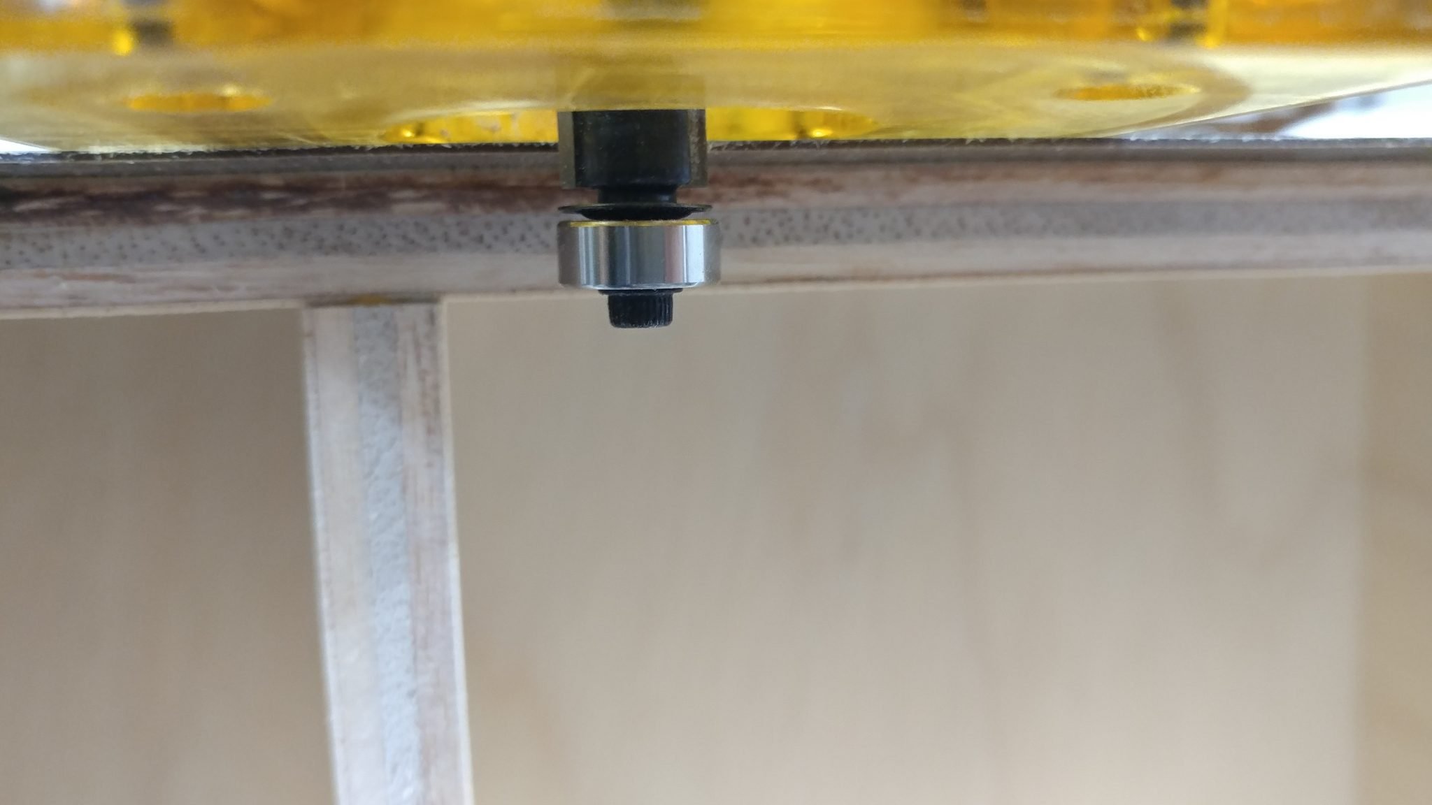
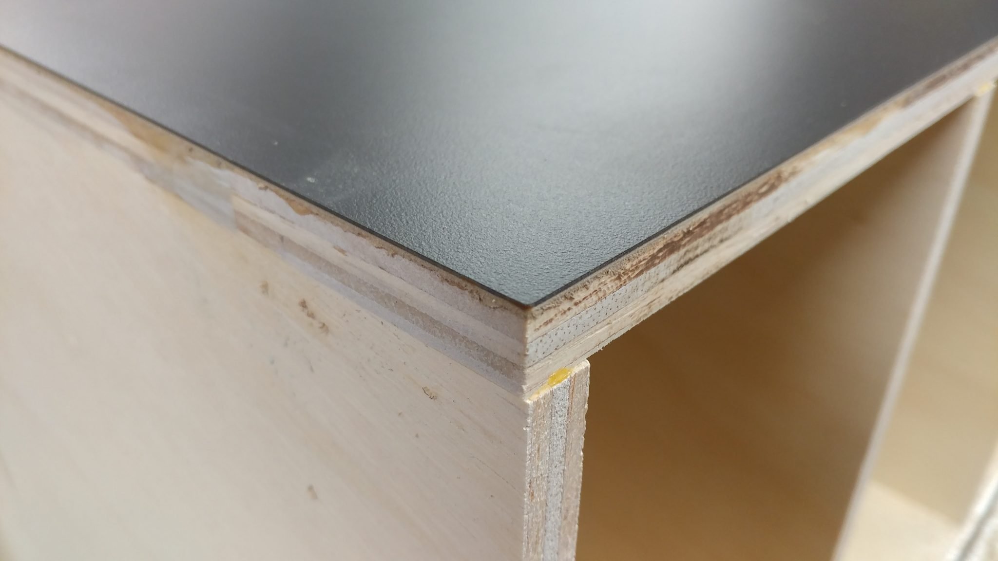
Route the edge.
The edge should be pretty smooth. One problem you may run into is that the contact adhesive will build up on the edges of the wood. This can get gummed up in the bearing on your bit or even make a bump that the bearing will roll over, causing you to have an uneven edge.
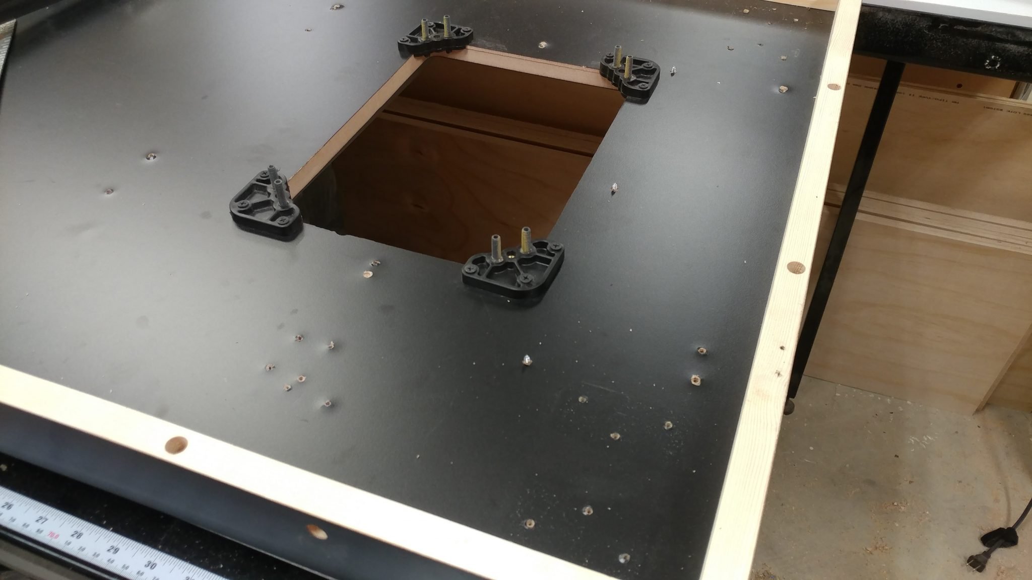
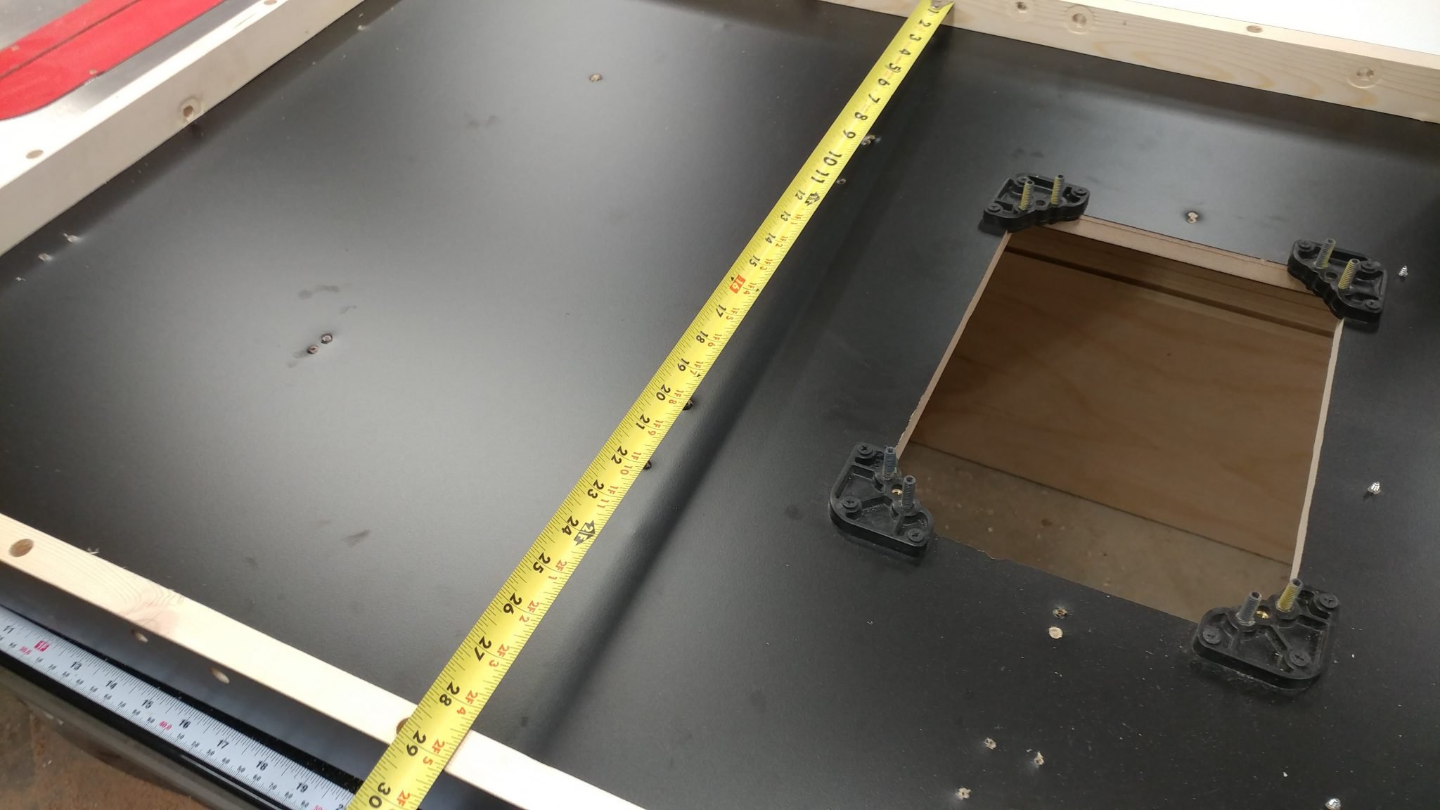
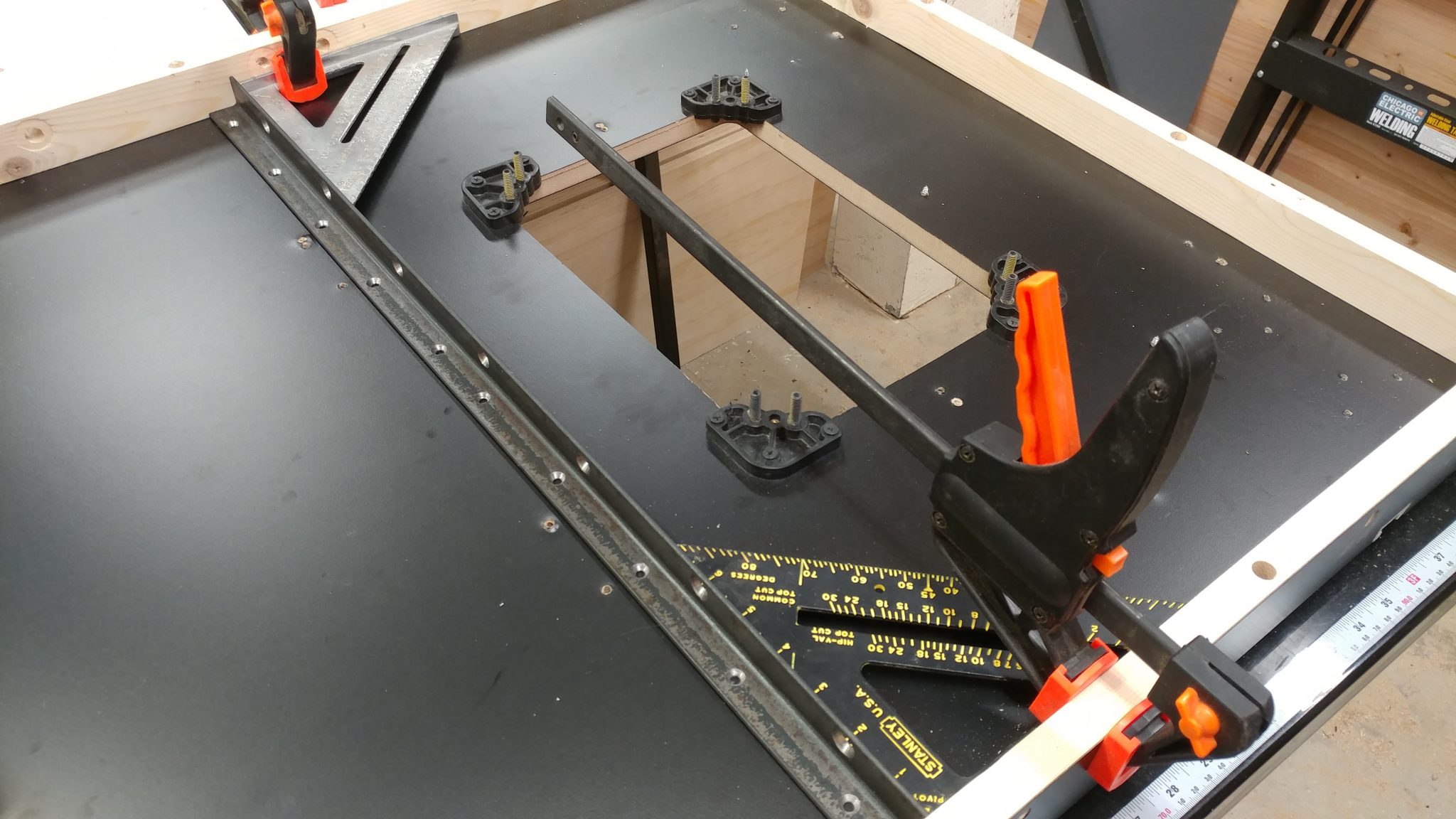
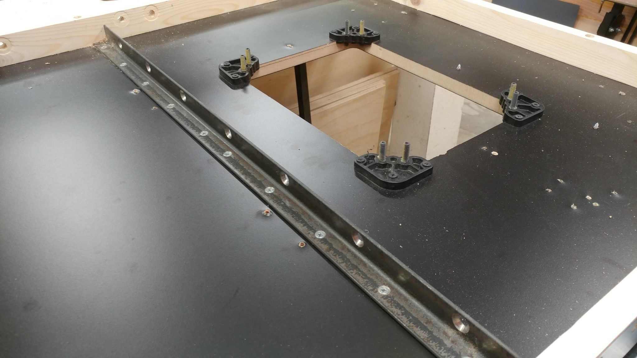
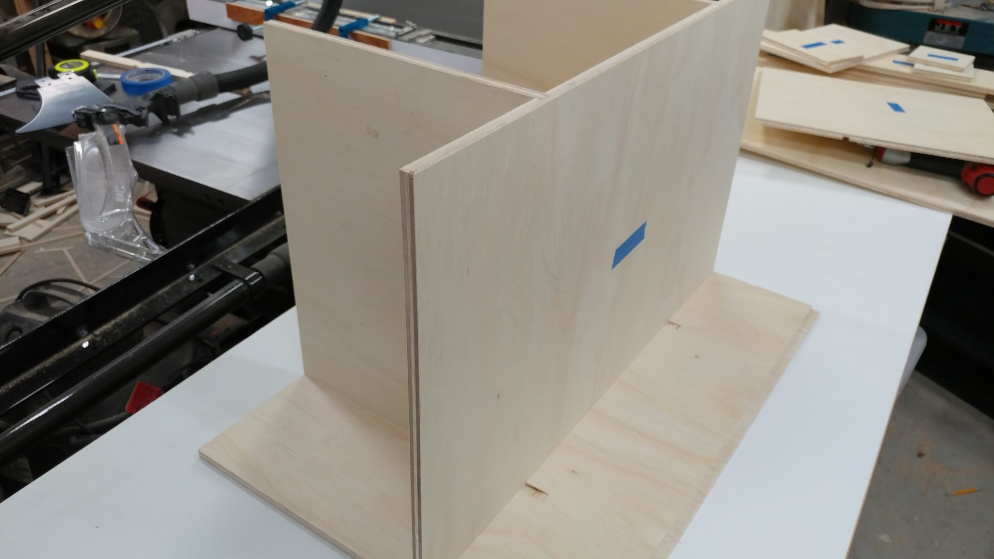
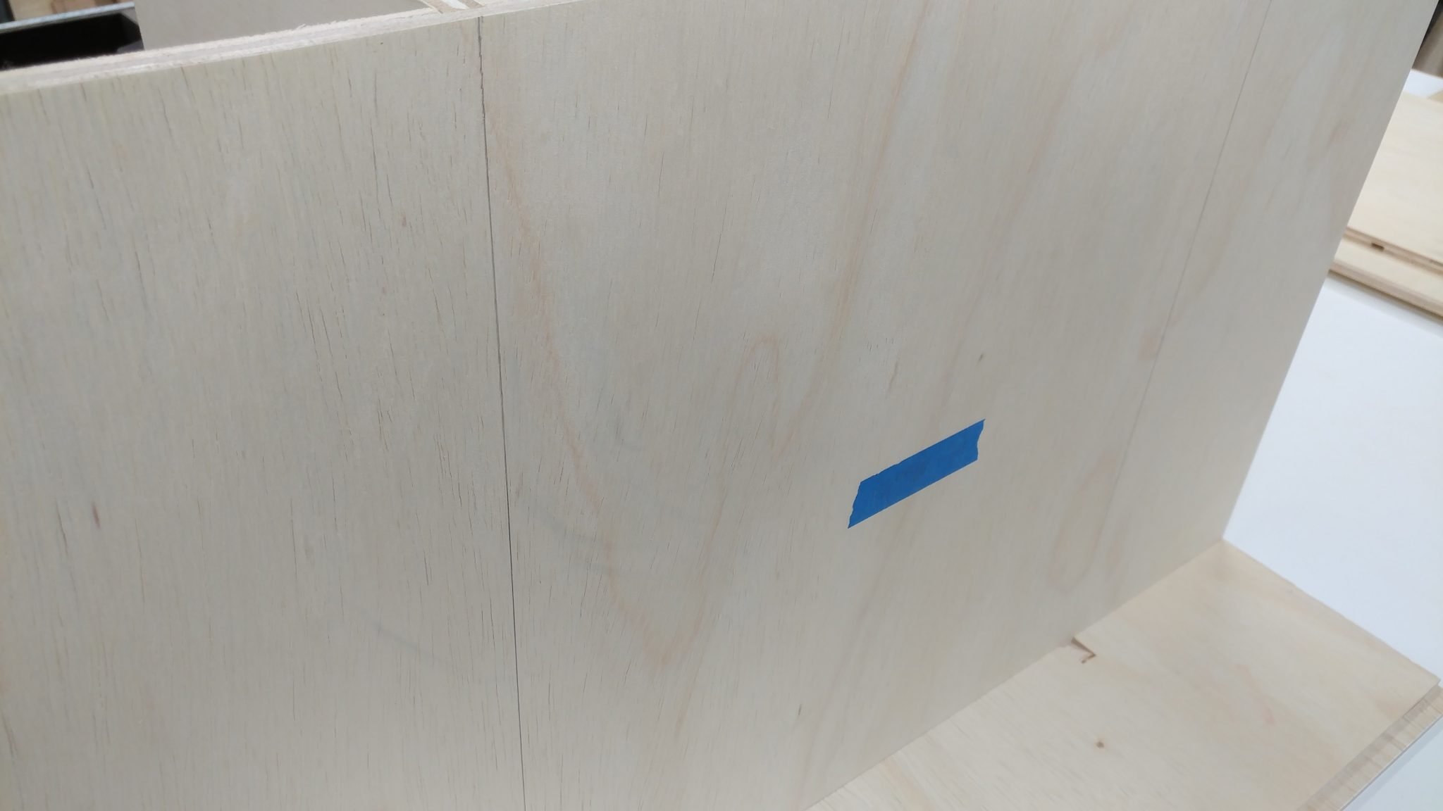
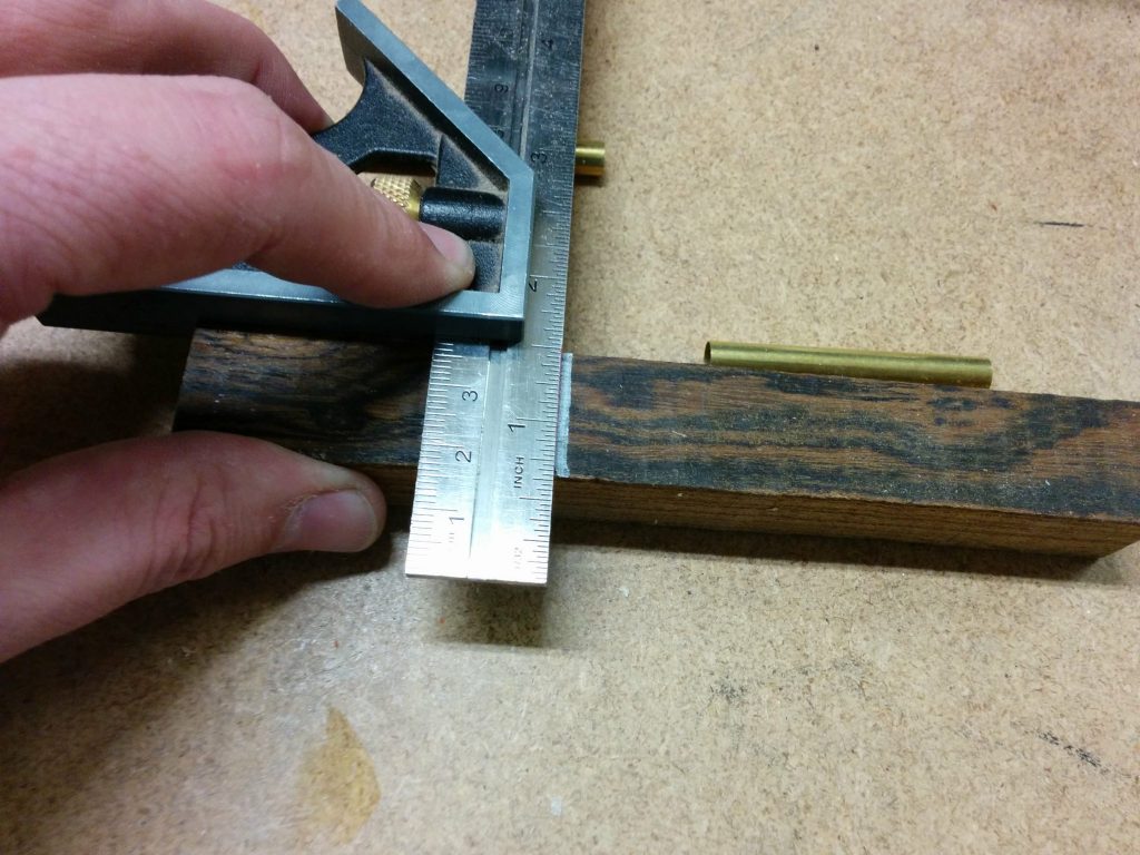
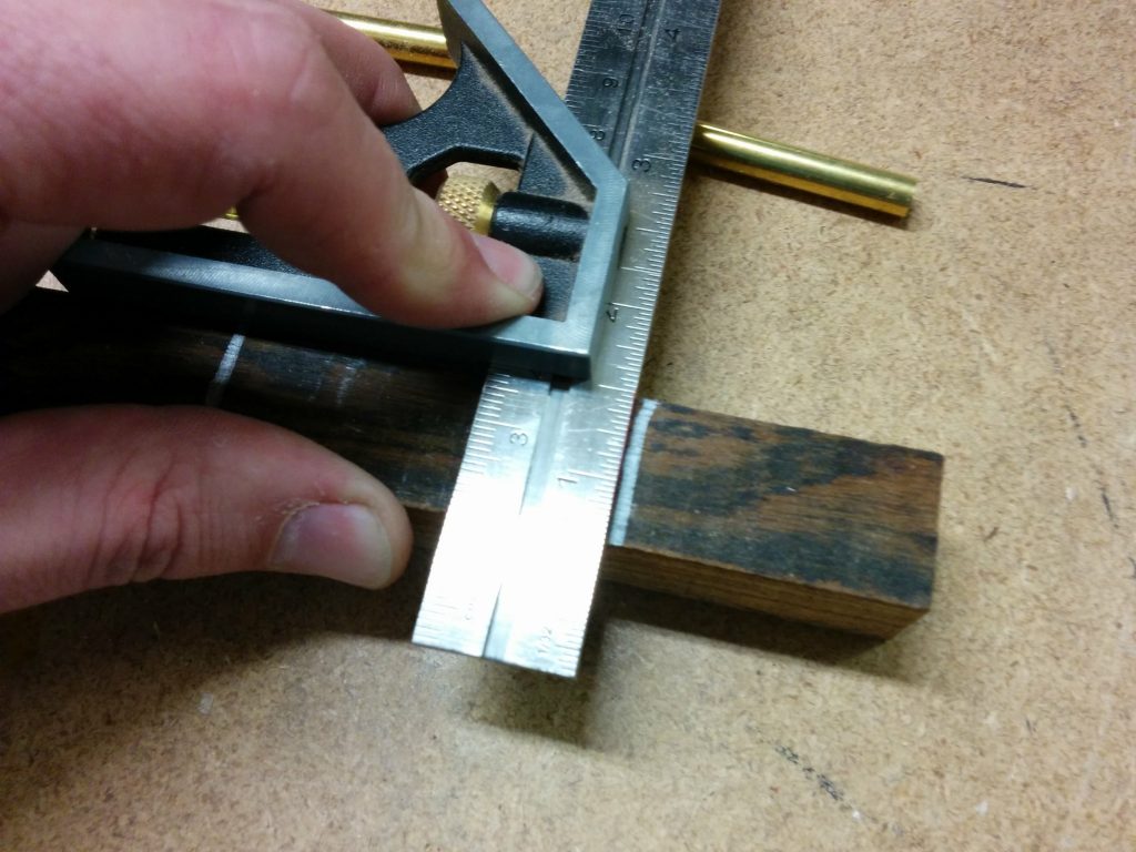
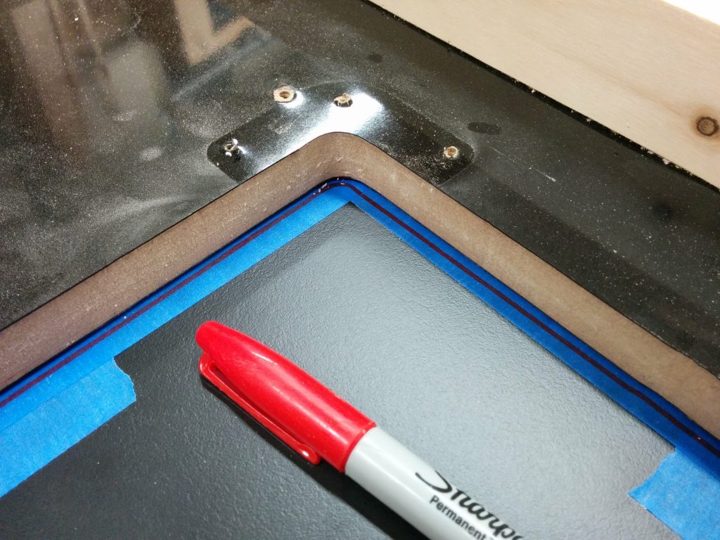
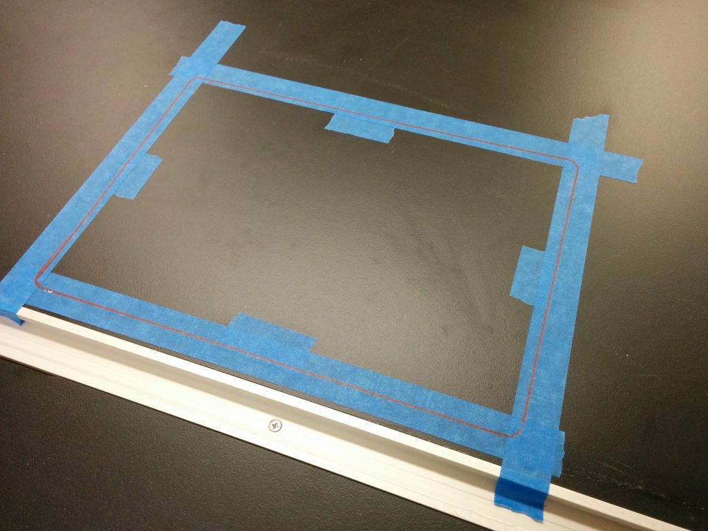
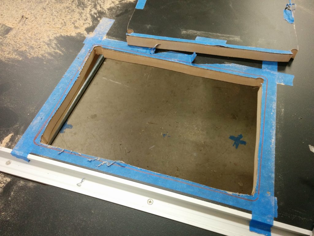
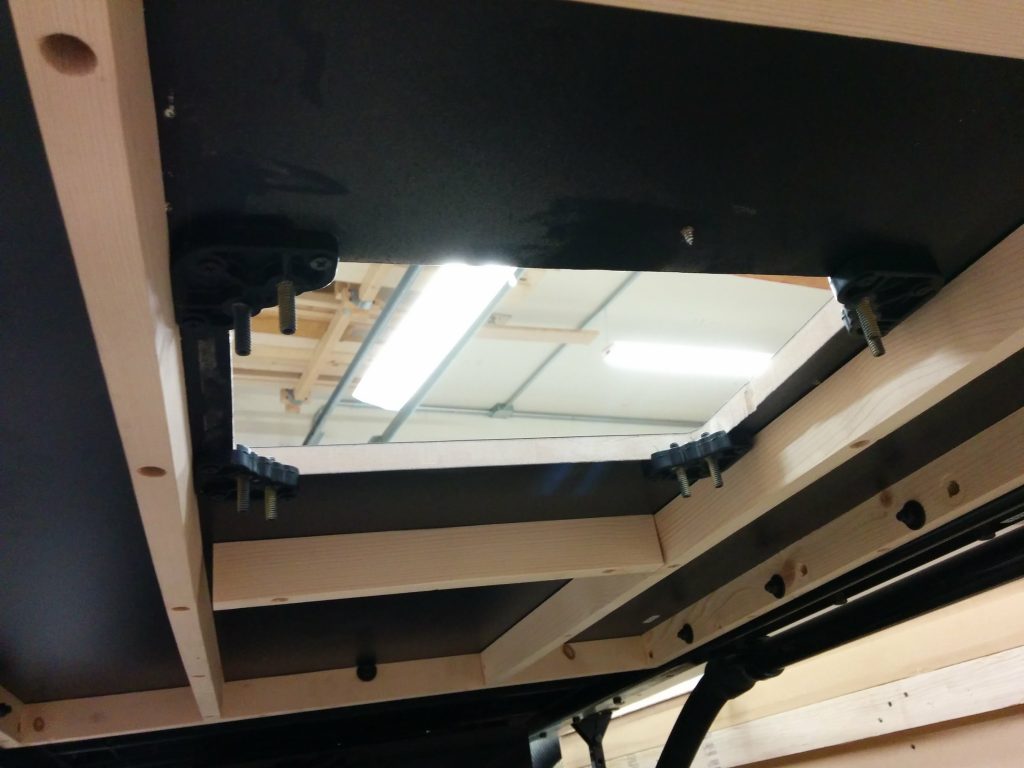
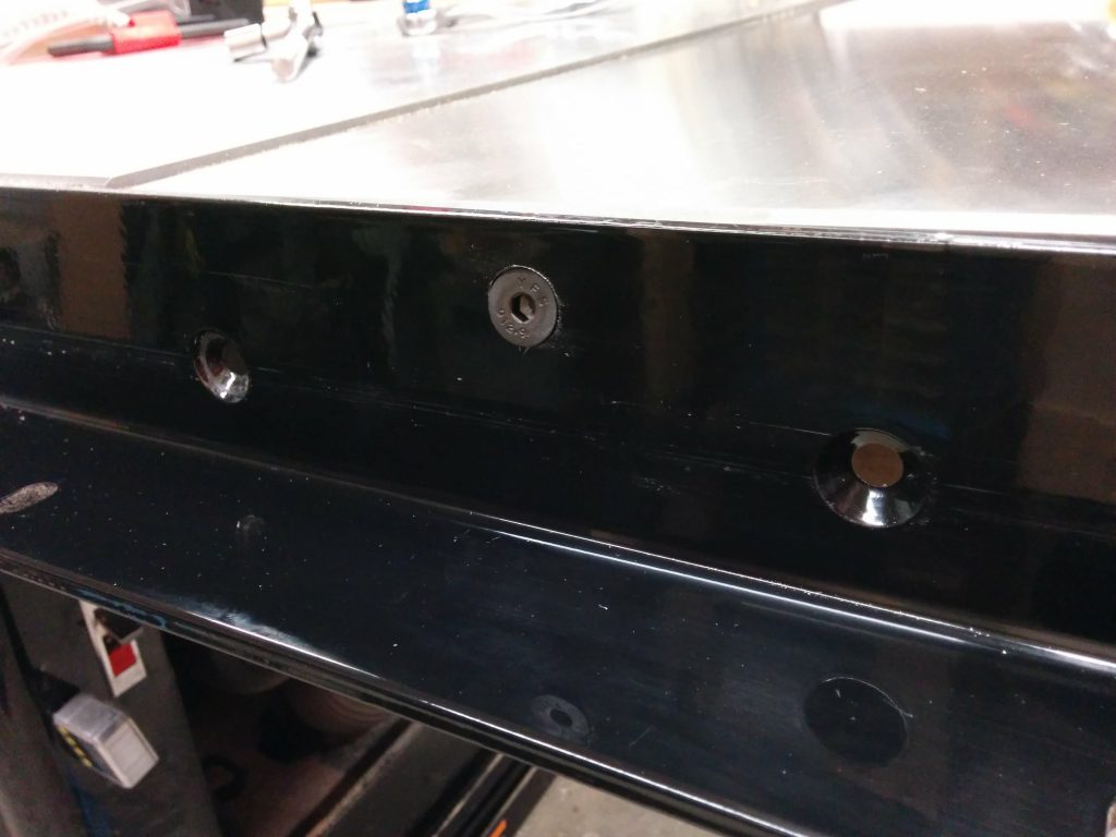
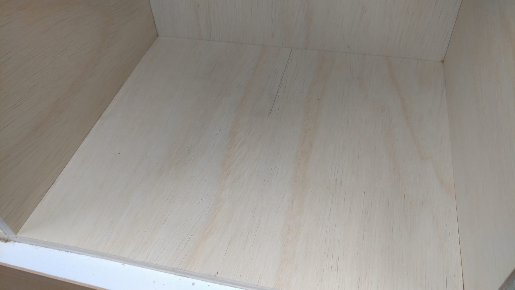
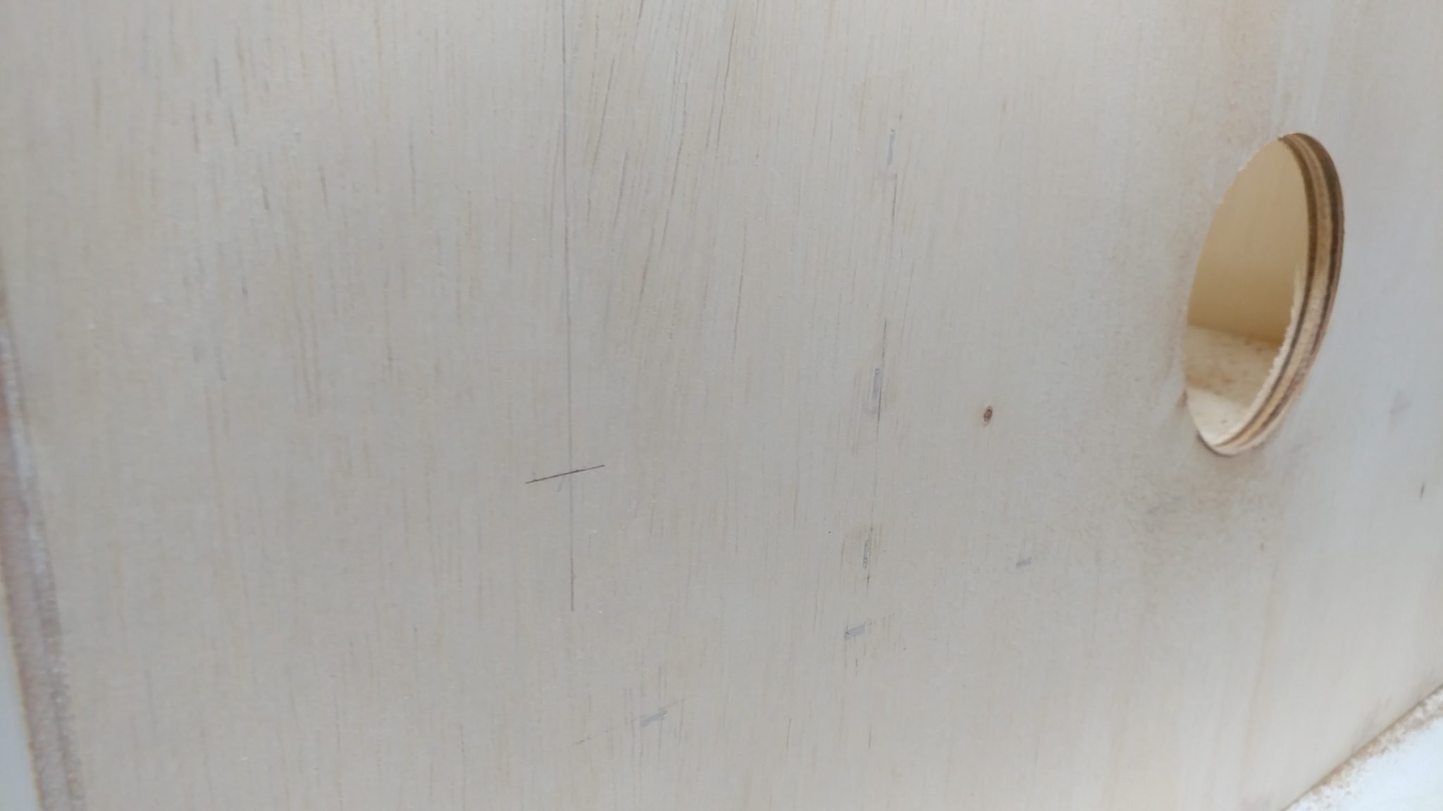
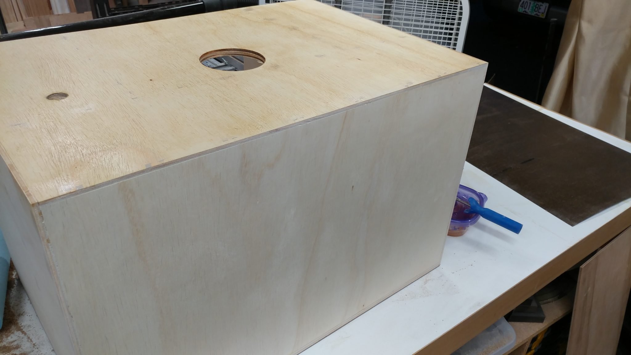
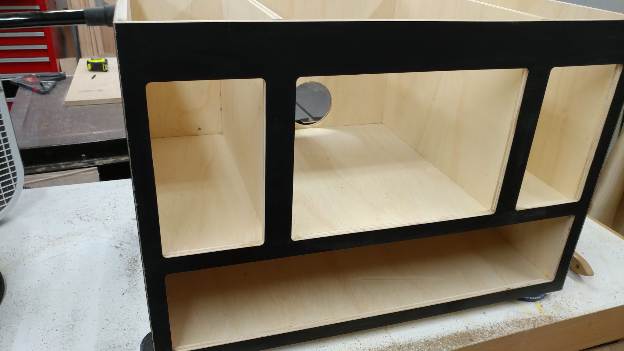
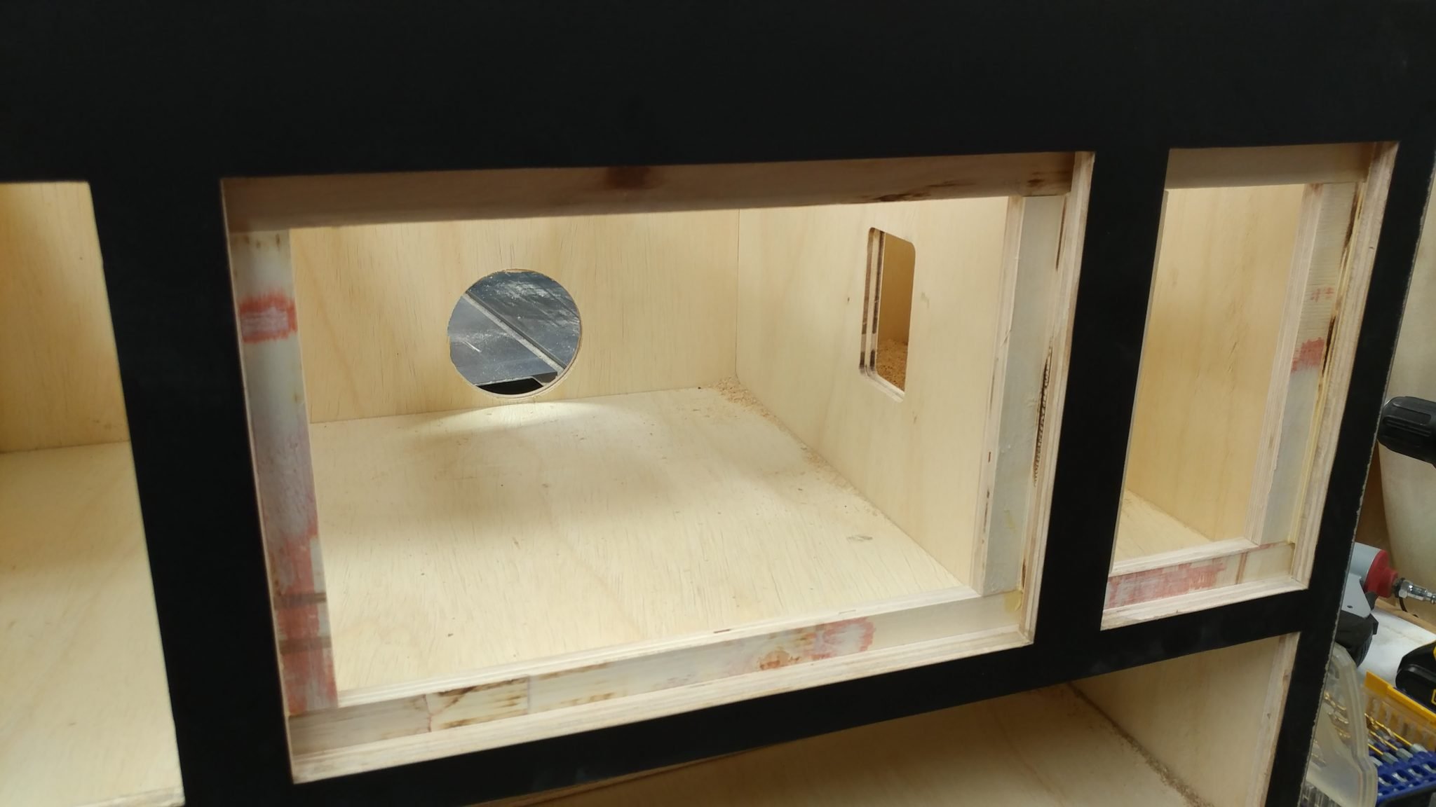
Before attaching the laminate to the back of the cabinet, I decided to drill the holes for the dust collection port and the wiring. I started by marking line on the center of the back wall. This view shows the cabinet sitting on it’s back so the surface we are looking at is the inside of the back wall.
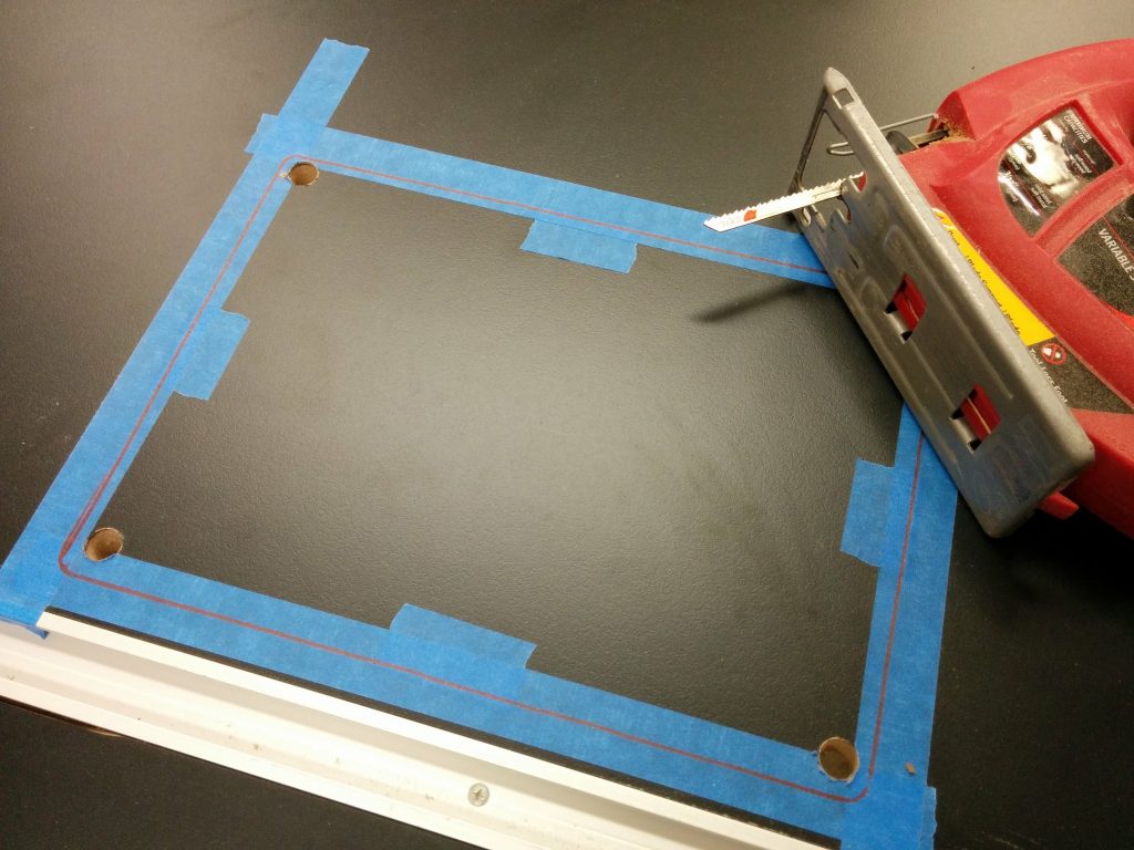
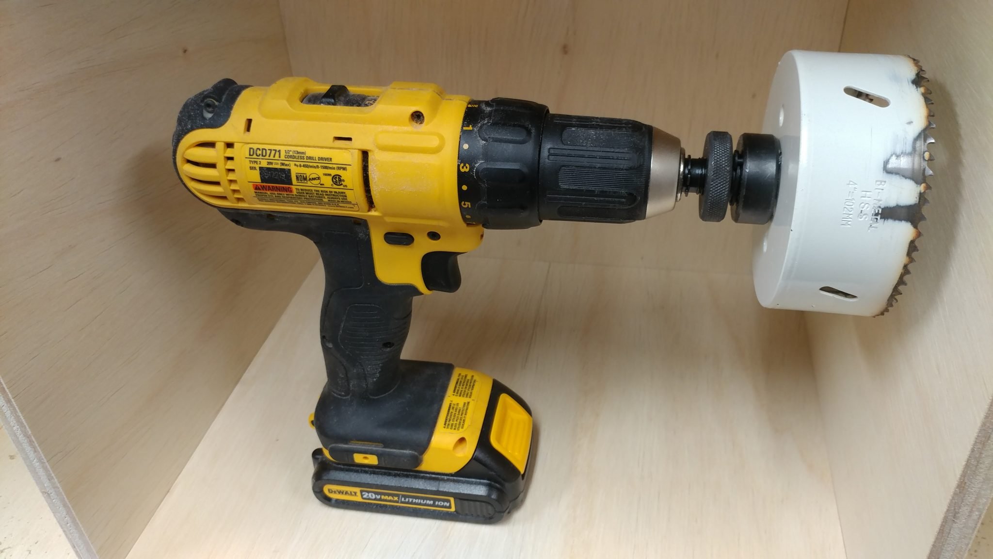
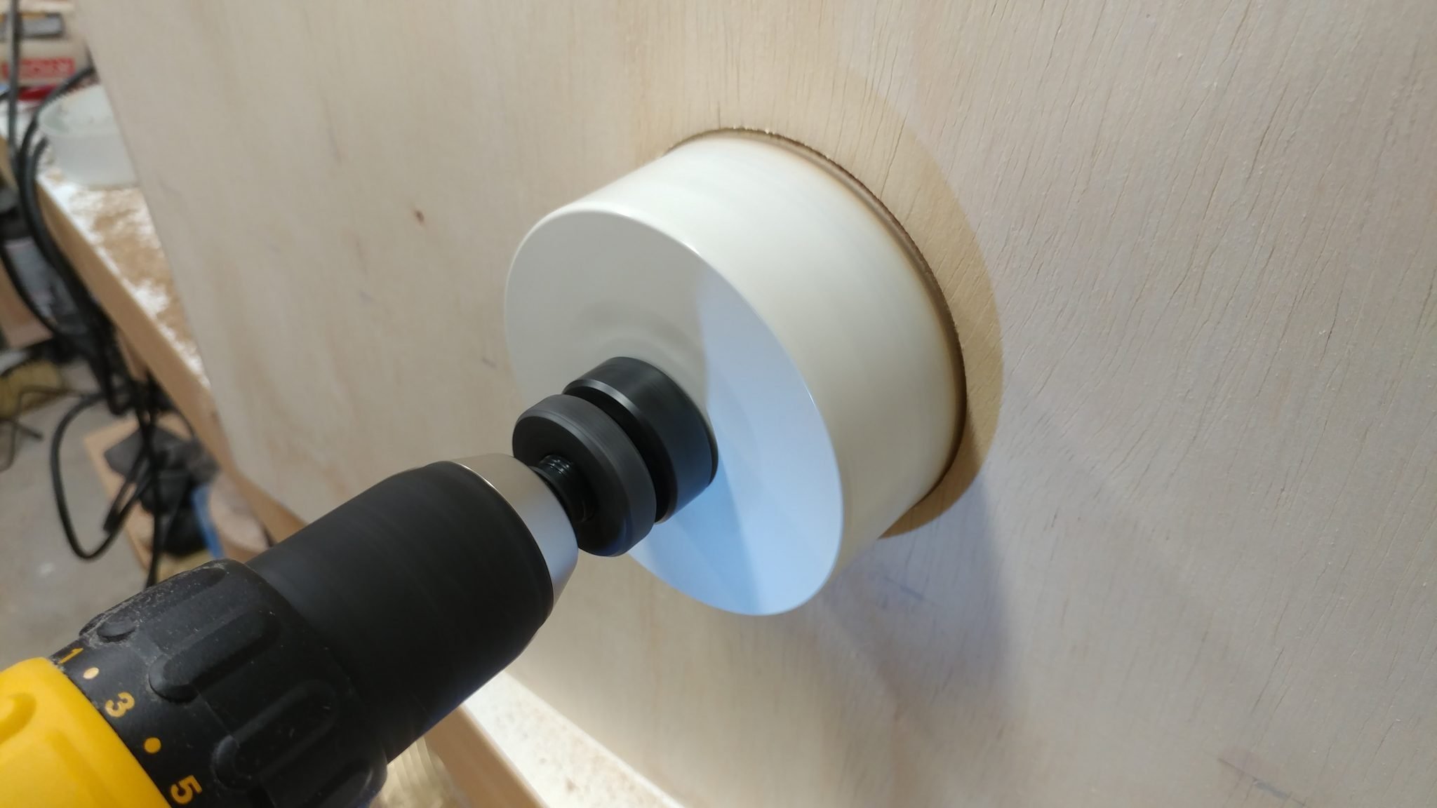
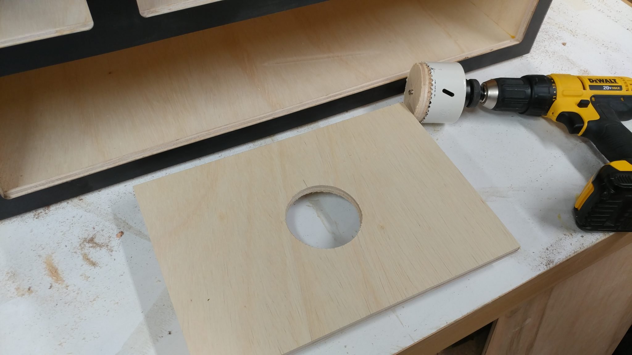
To cut the hole, I used a 4″ hole saw on my cordless drill.
I started from the inside and cut it about halfway through.
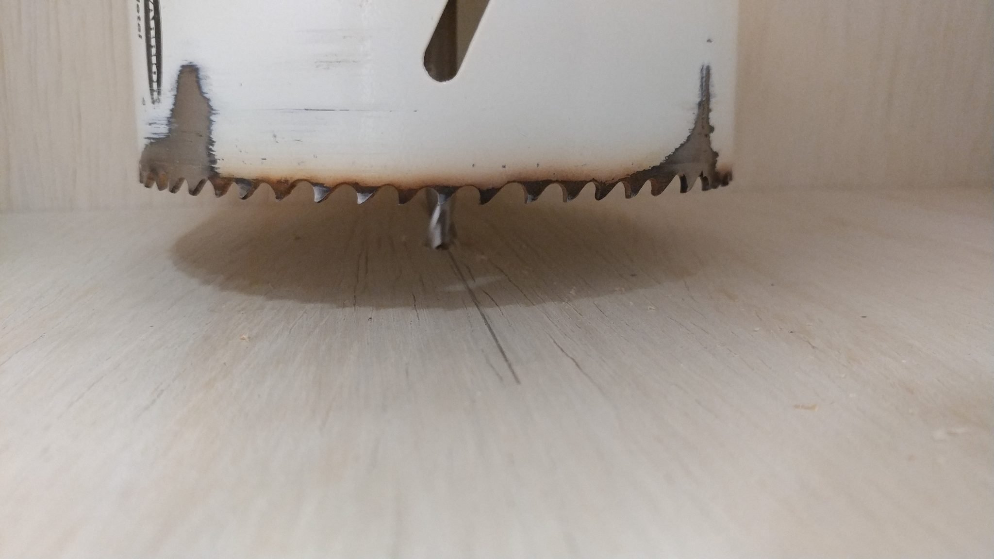
Then I switched to the outside, inserting the pilot bit into the hole that I made from the inside. Cutting halfway through from each edge helps prevent tearout.
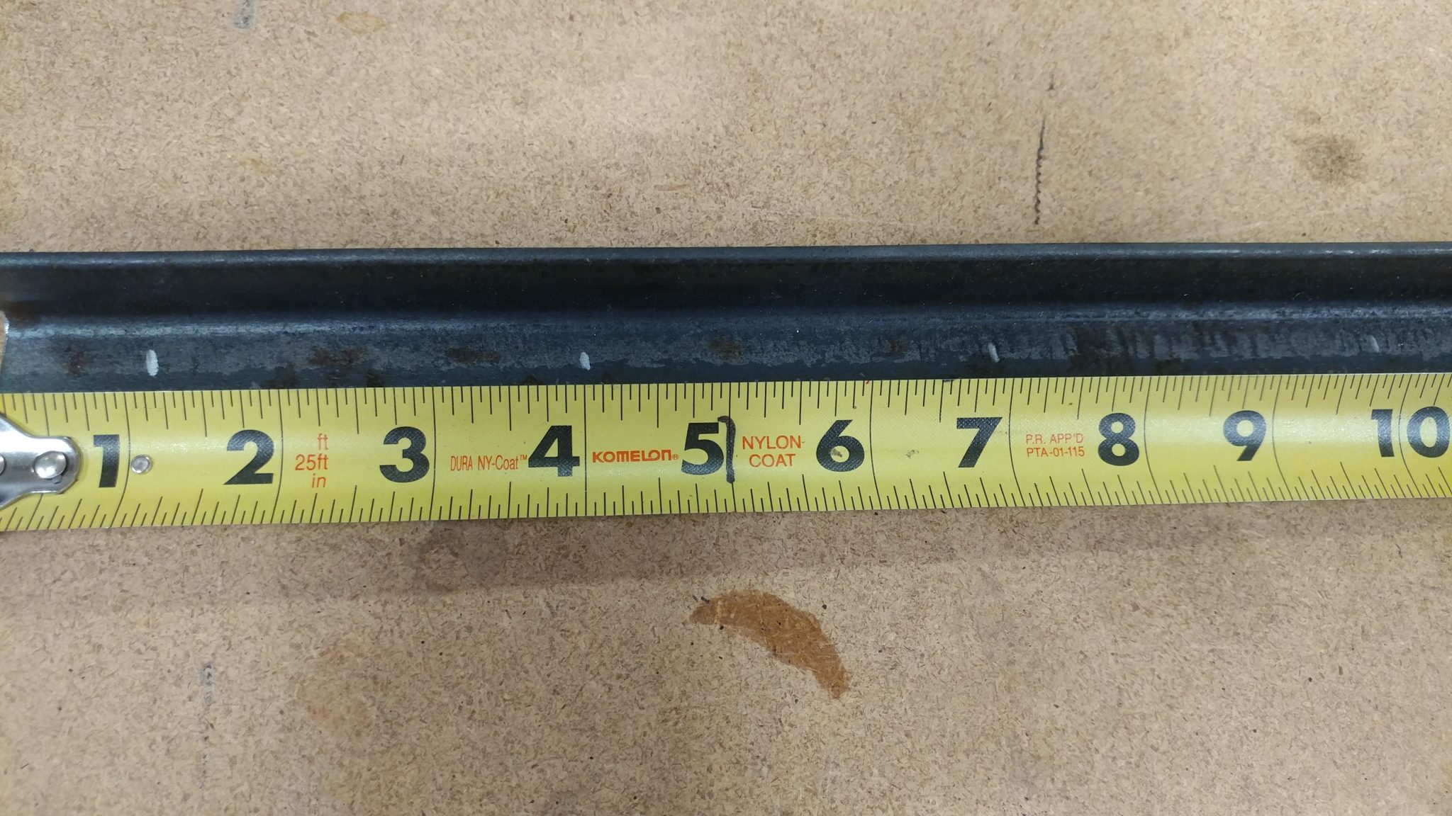
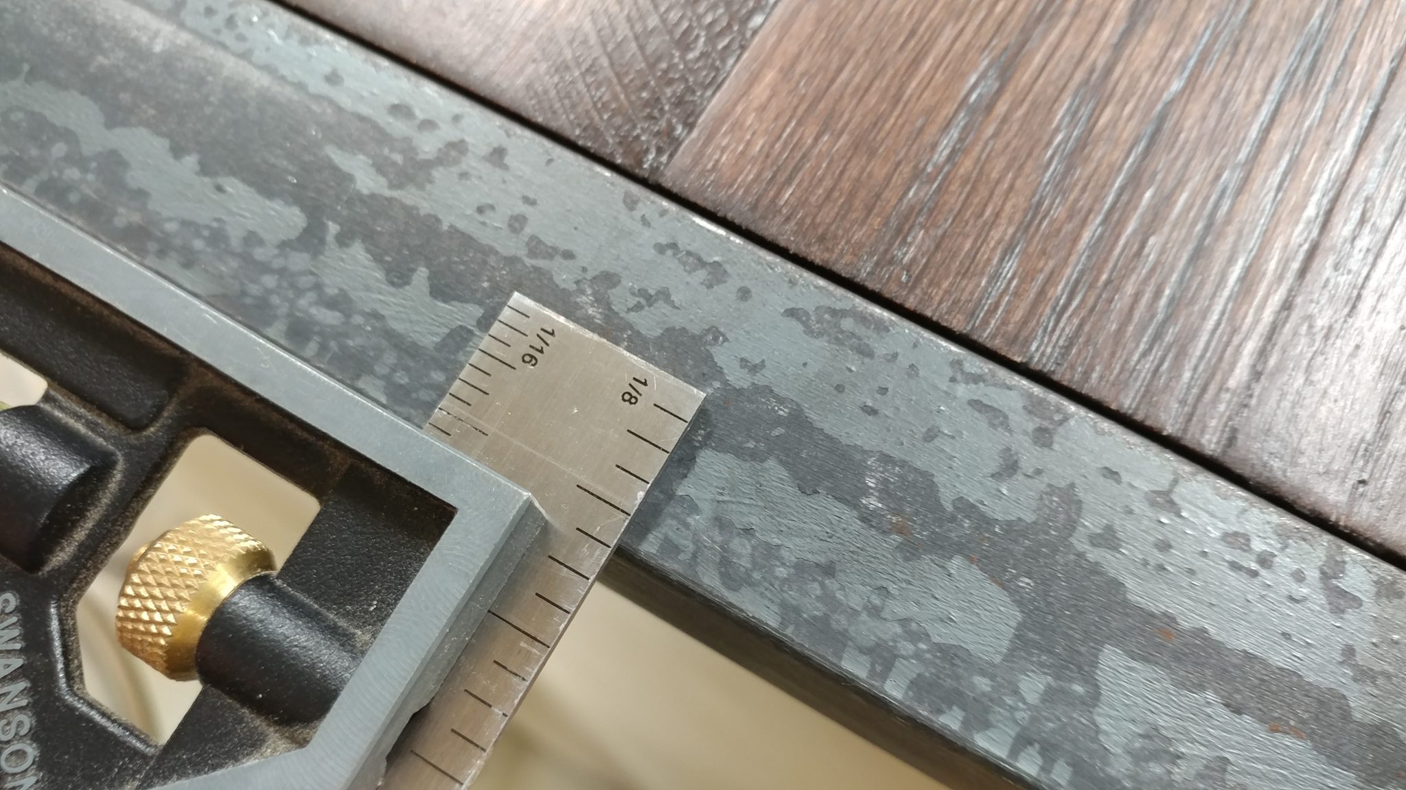
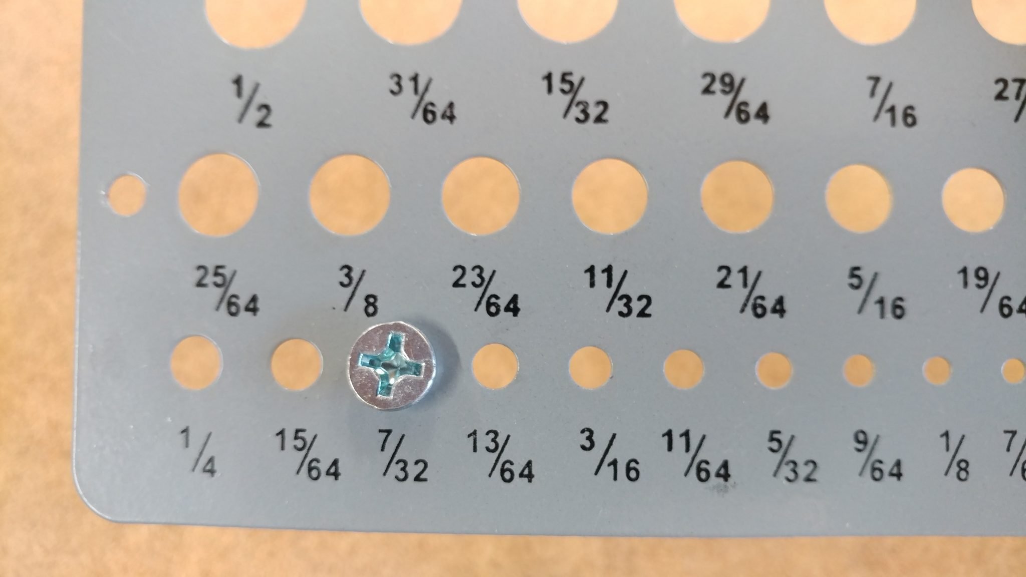
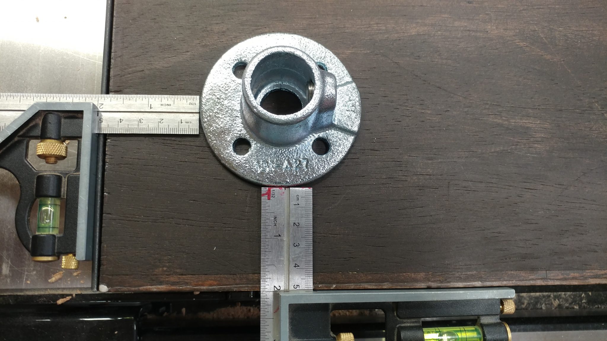
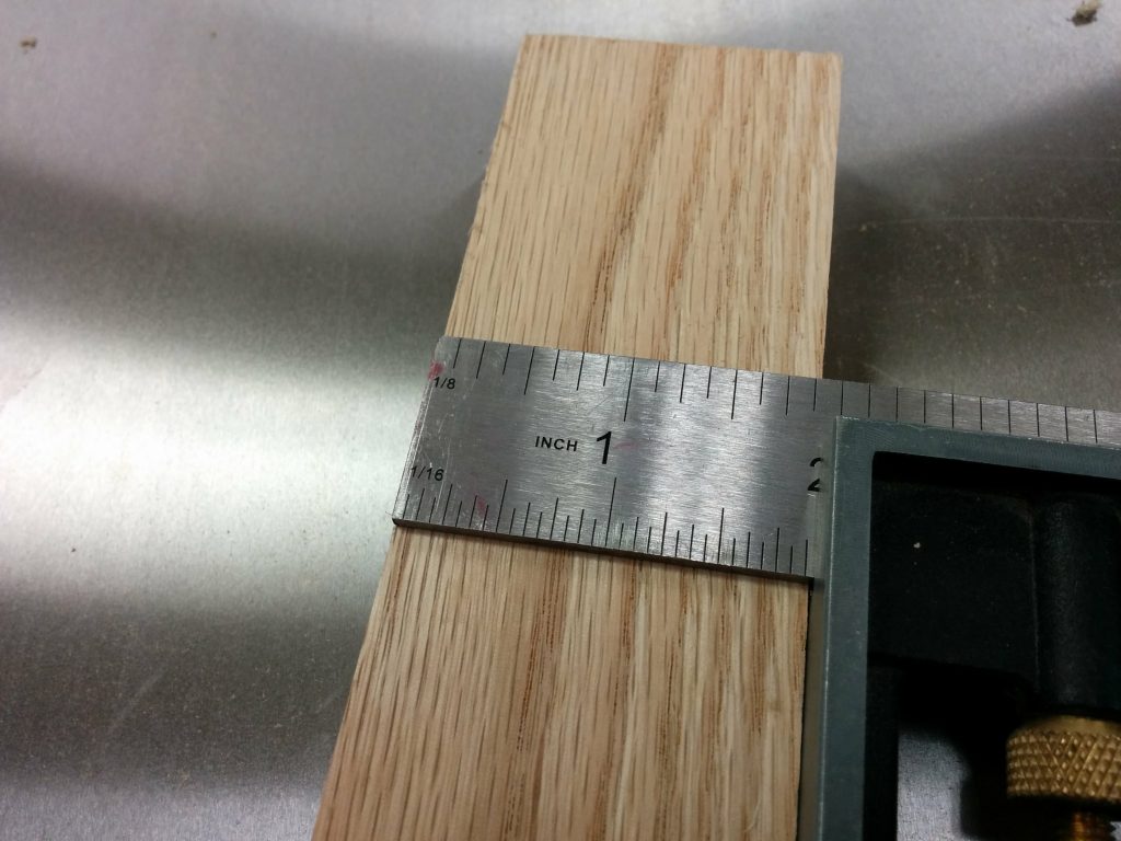
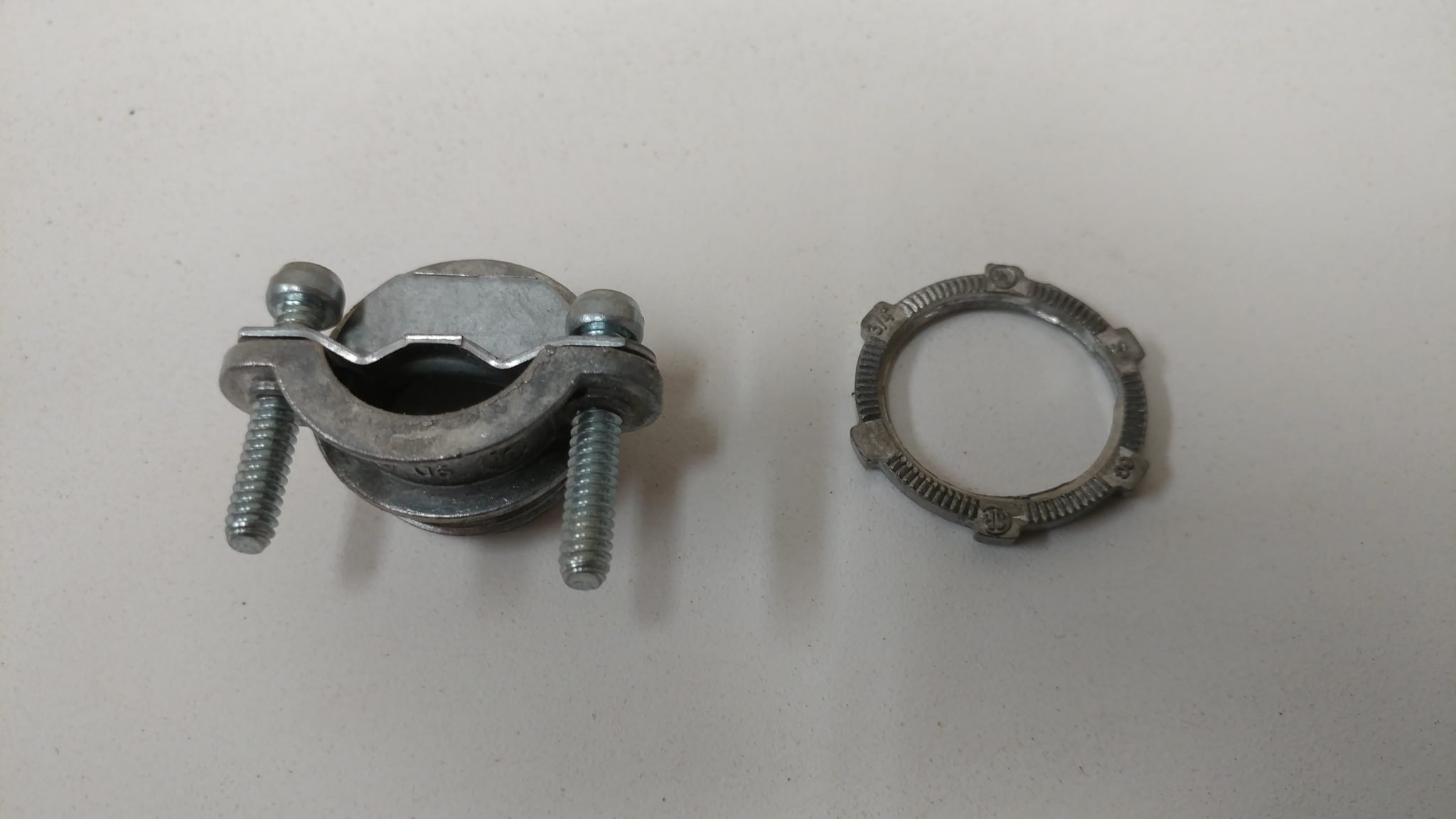
I’m using a strain relief that you would normally using when putting in a junction box. It measures almost 1″ in diameter on the threaded end. I won’t be using the threaded ring so I take that off.
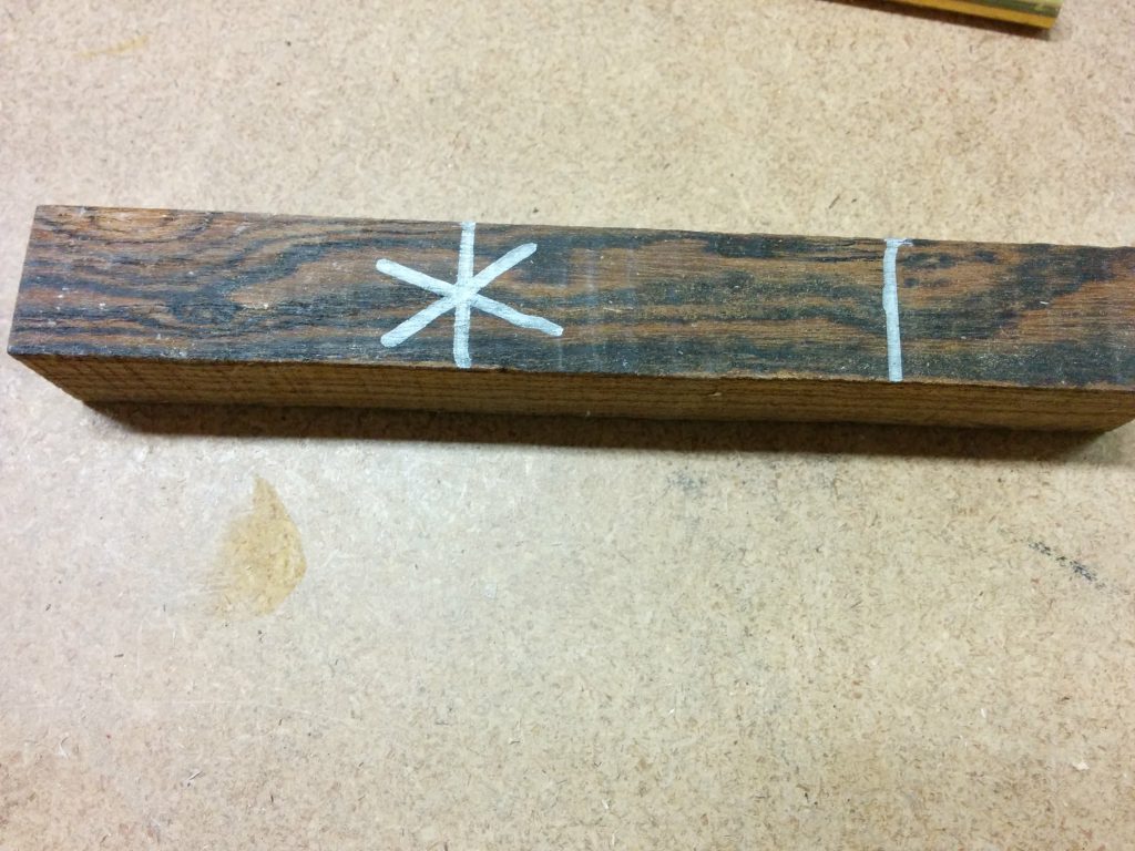
I marked where it would look best to drill the hole.
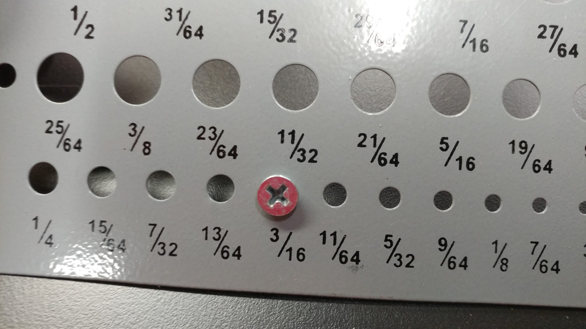
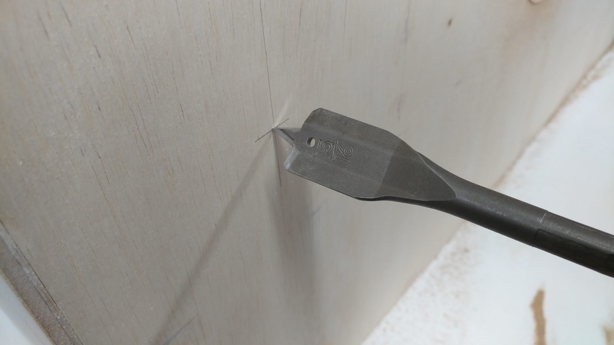
I decided to try using a 15/16″ spade bit. I should have just used a 1″ bit.
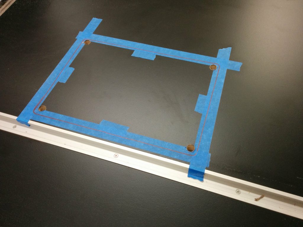
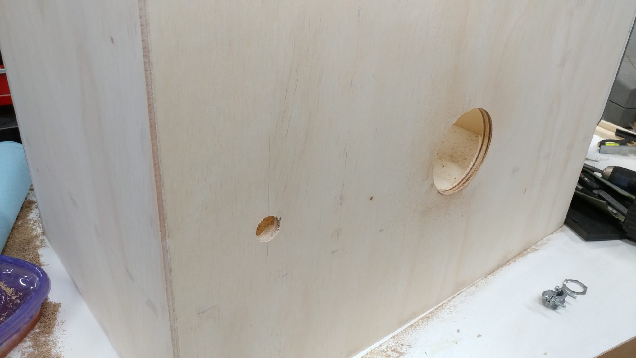
Both the holes have been cut out.
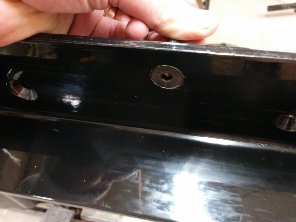
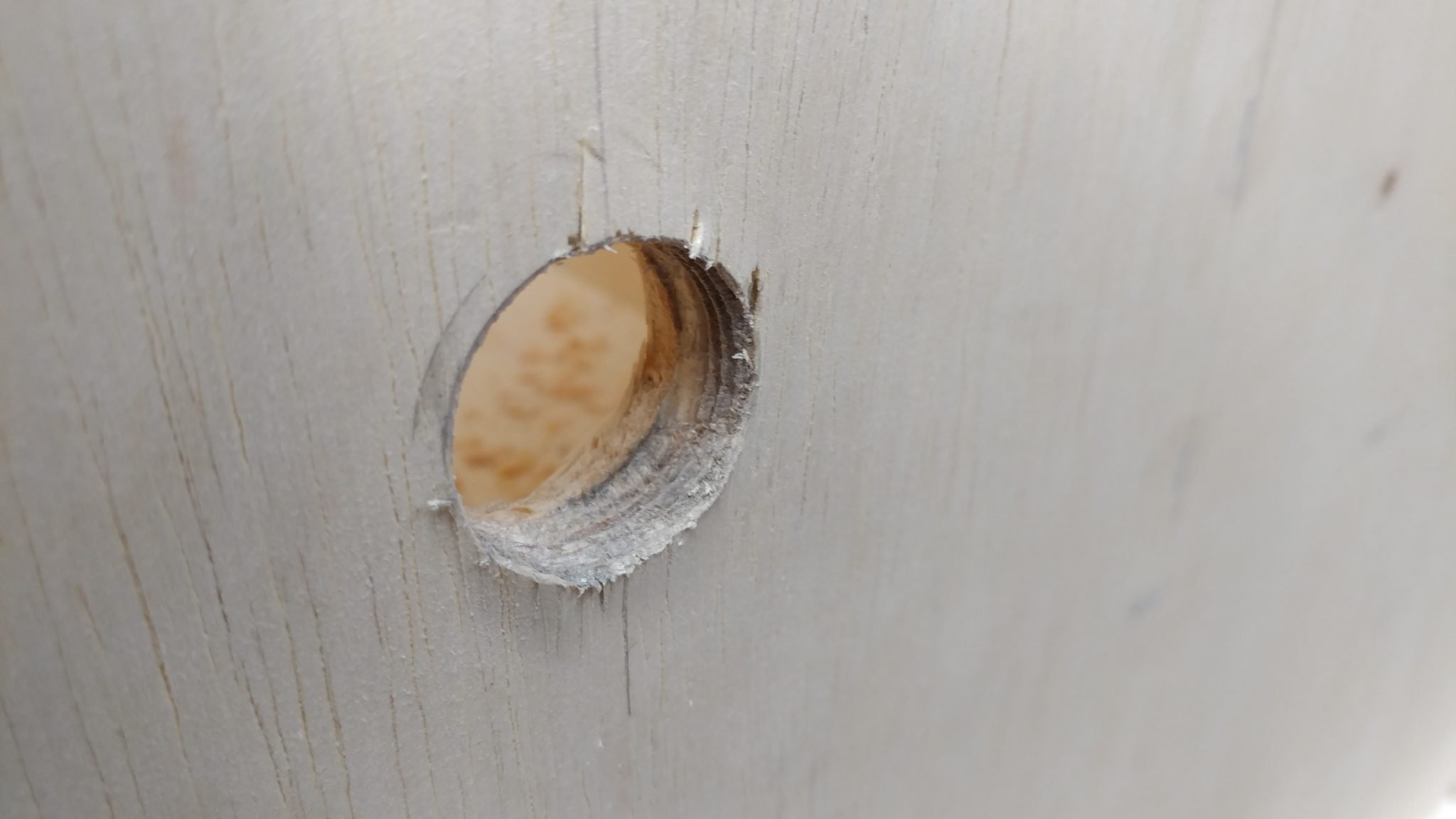
I inserted the strain relief in order to cut some threads in the hole. I wanted to do this now rather than after I got the laminate in place so it wouldn’t get all scratched up.
I apply the contact cement to the back laminate piece…
…and to the back of the cabinet.
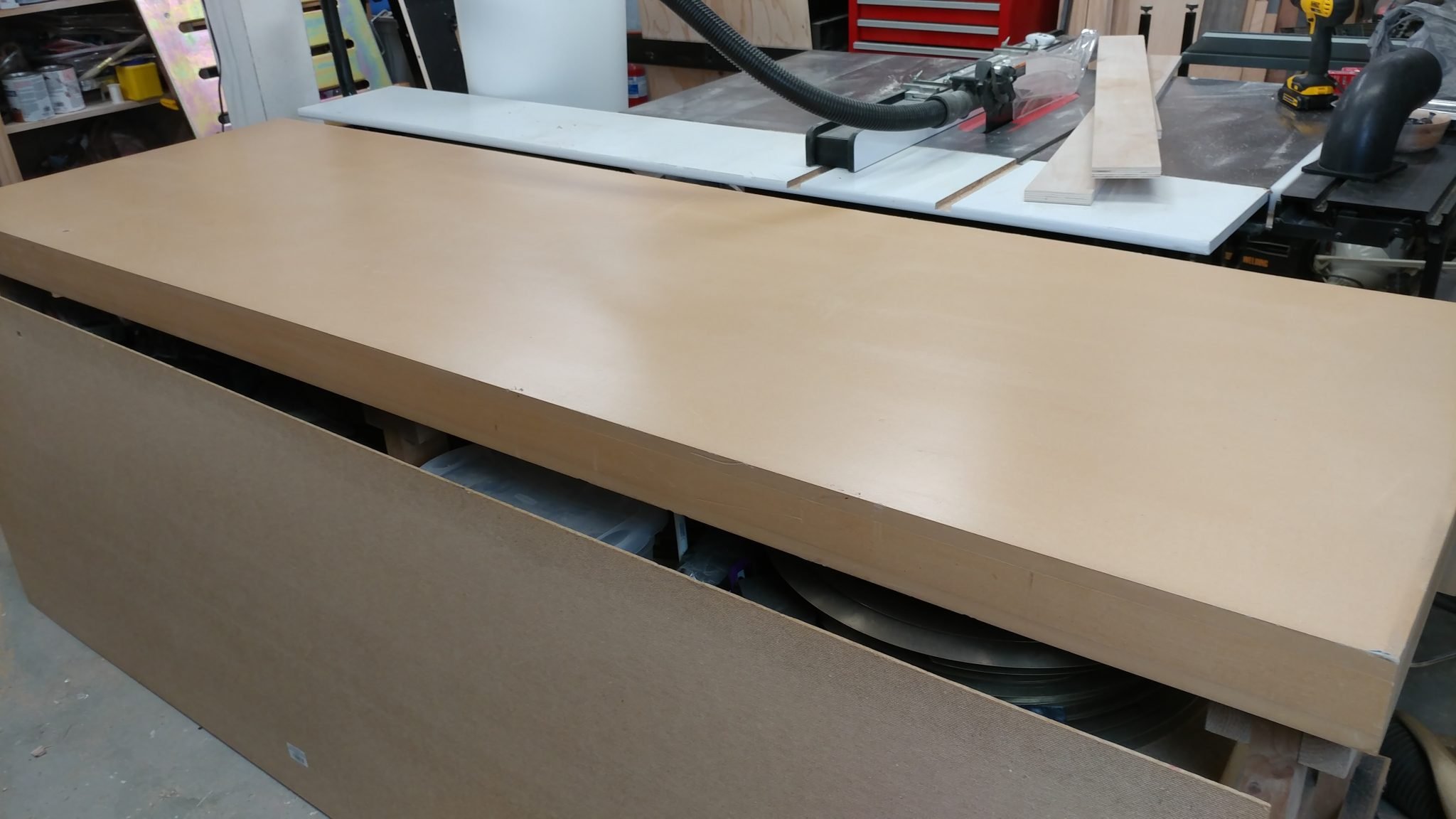
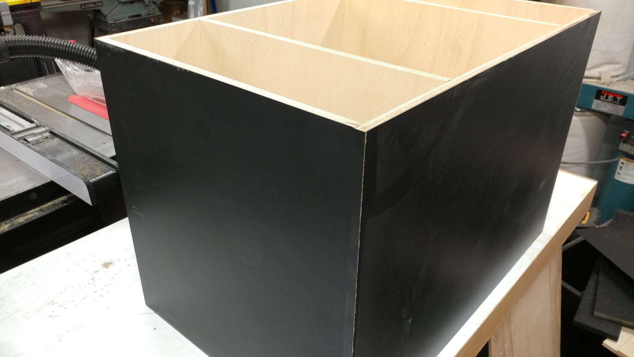
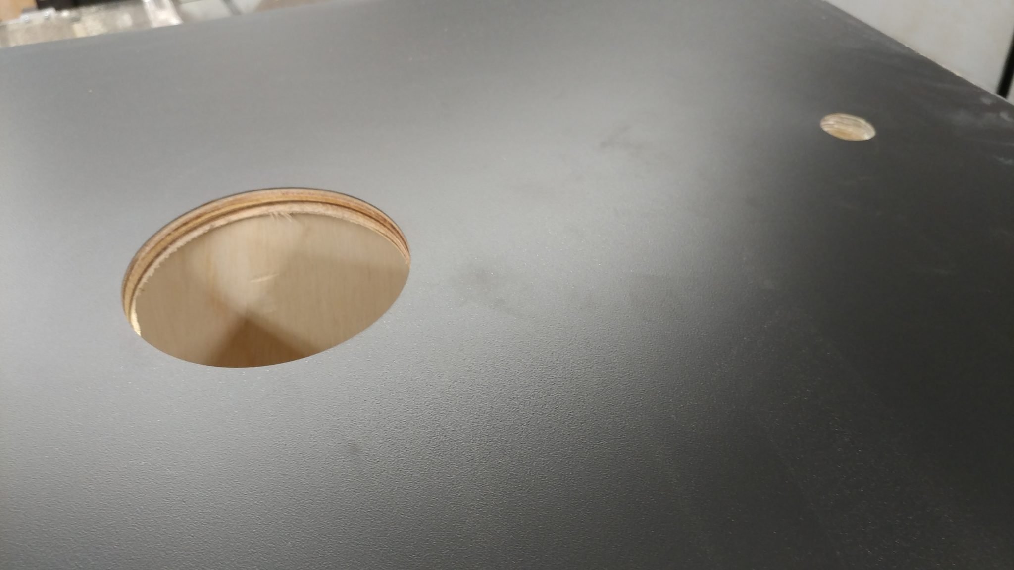
Then I applied the laminate and trimmed it like I did the front. Notice that the holes are covered with the laminate. I’ll cut them out later.
I then applied the laminate to both ends. I didn’t apply any to the underside since that won’t be seen.
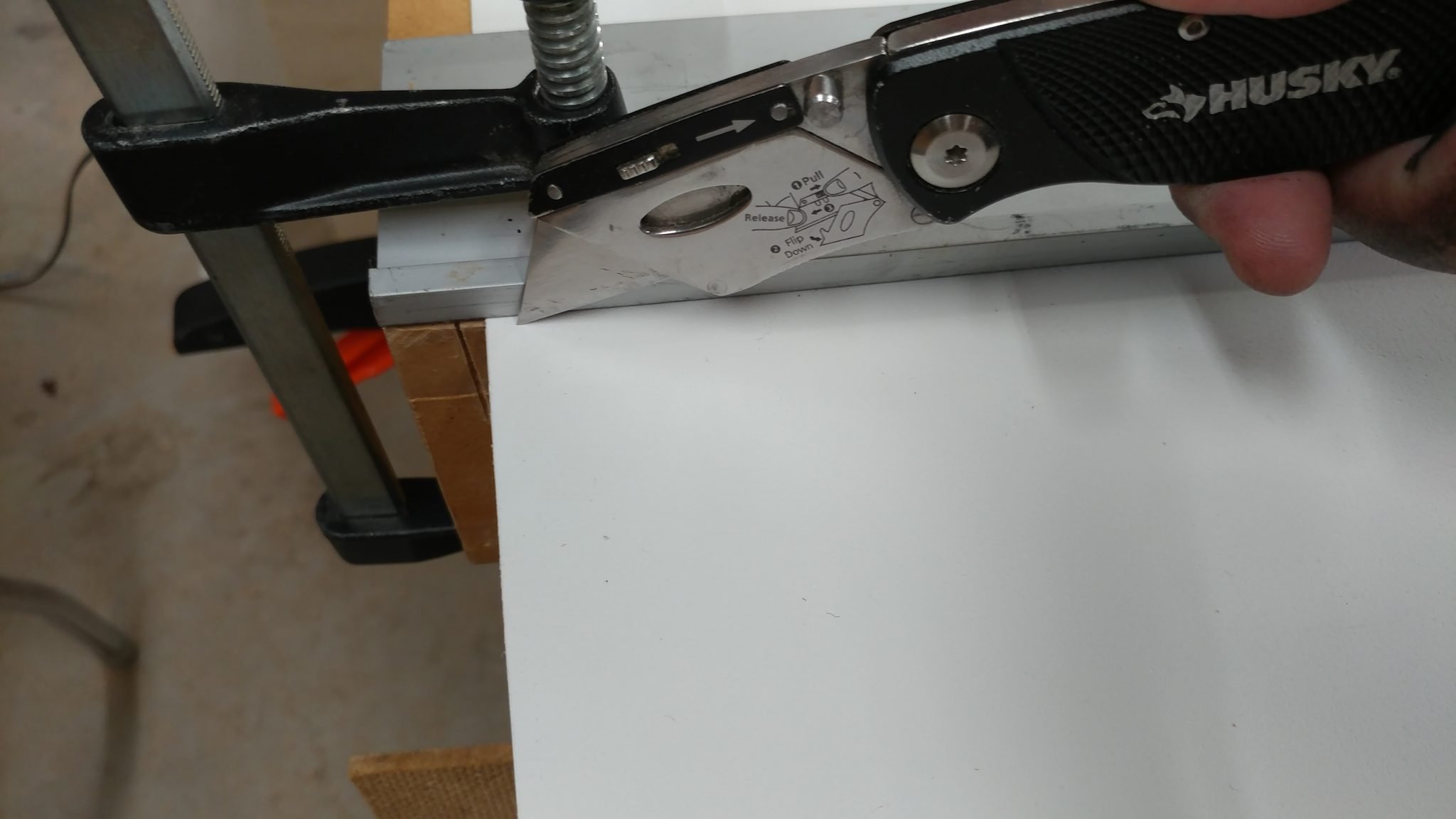
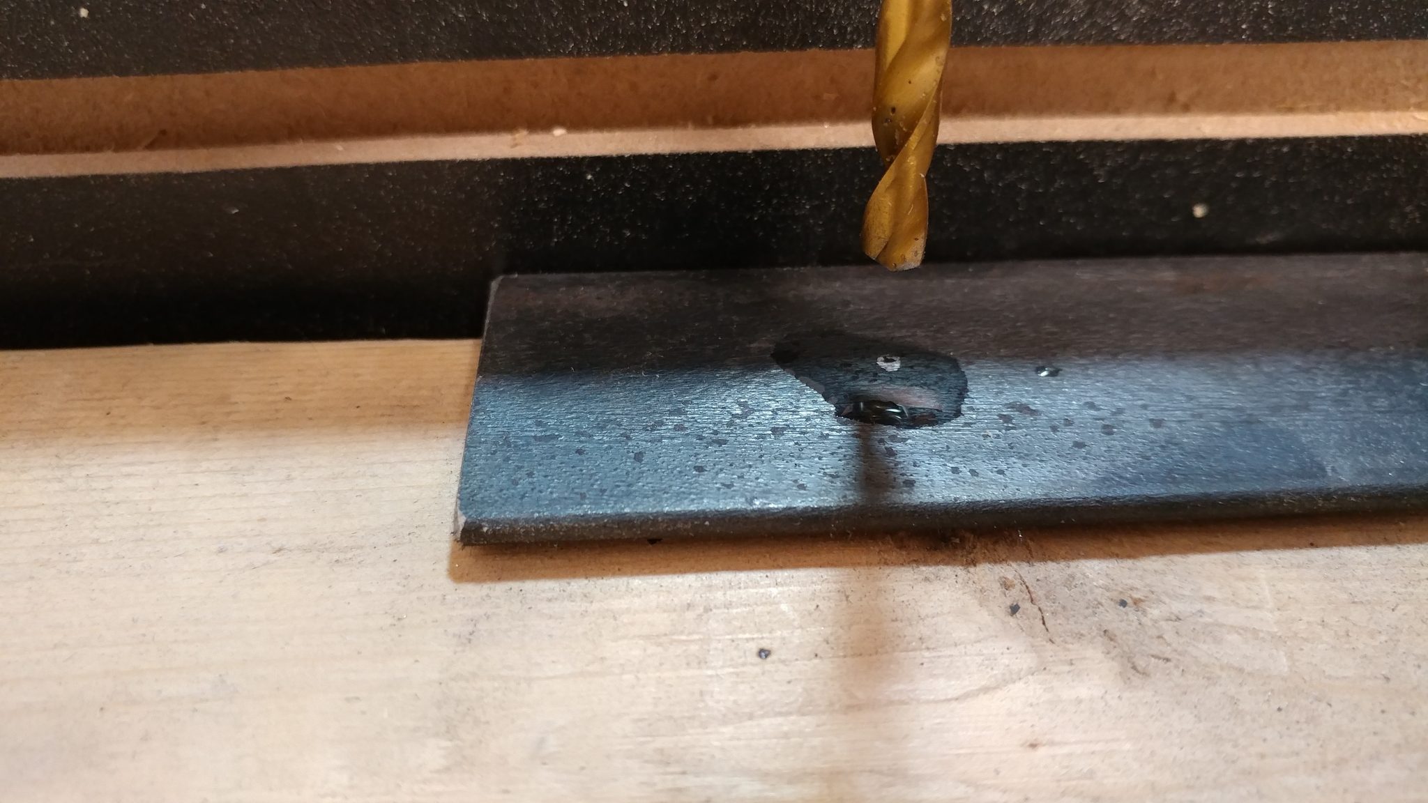
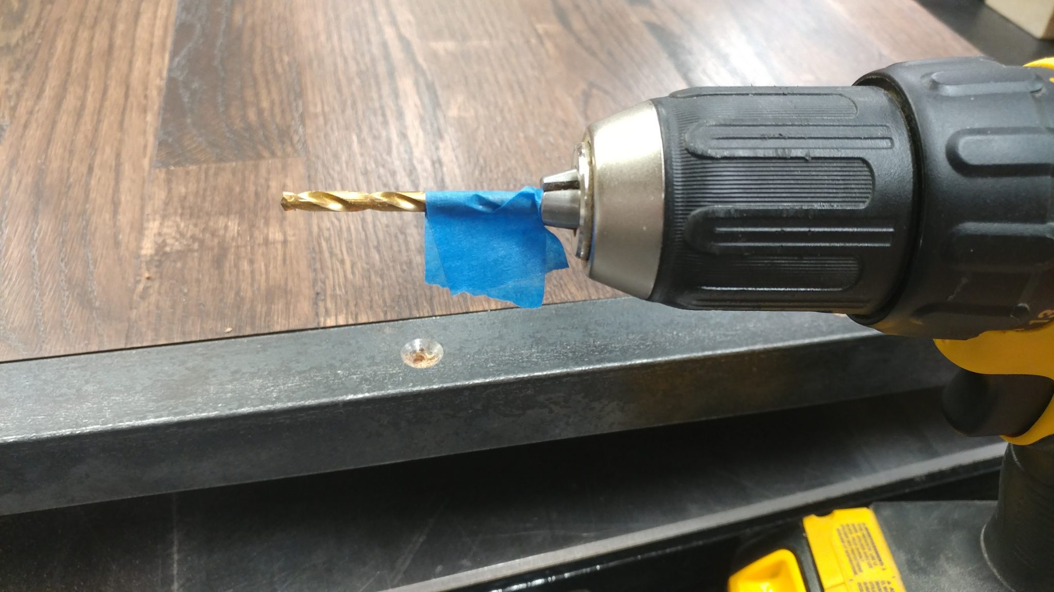
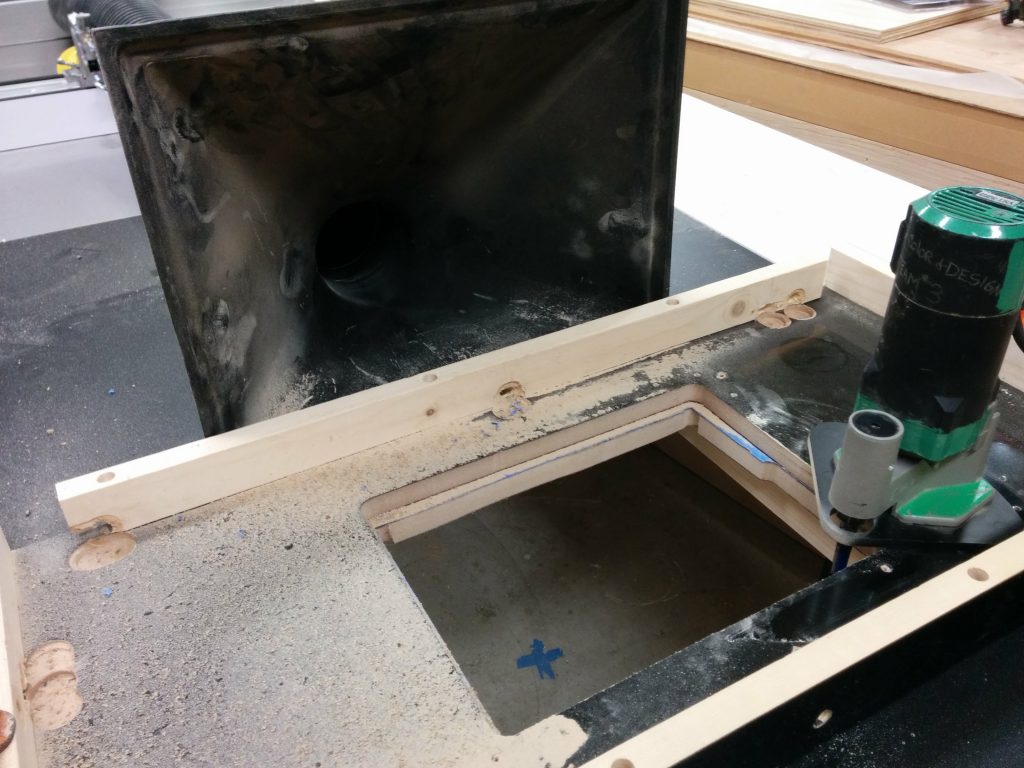
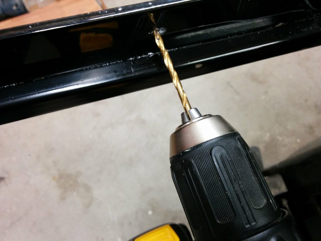
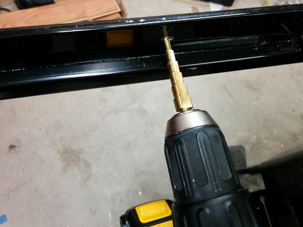
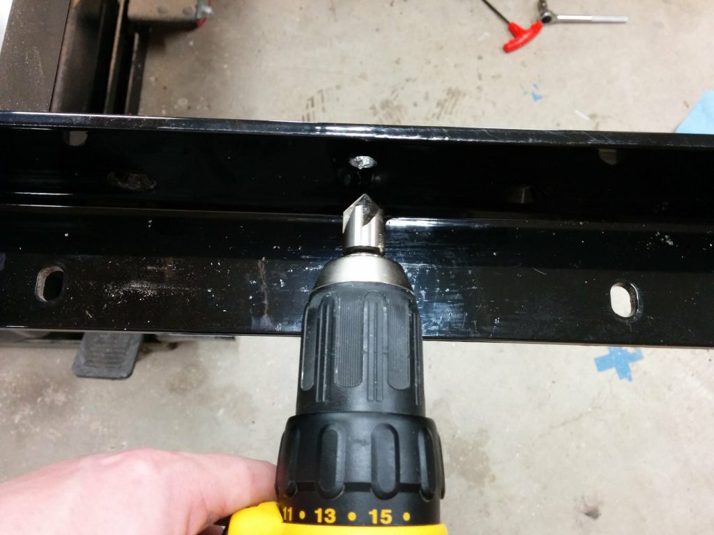
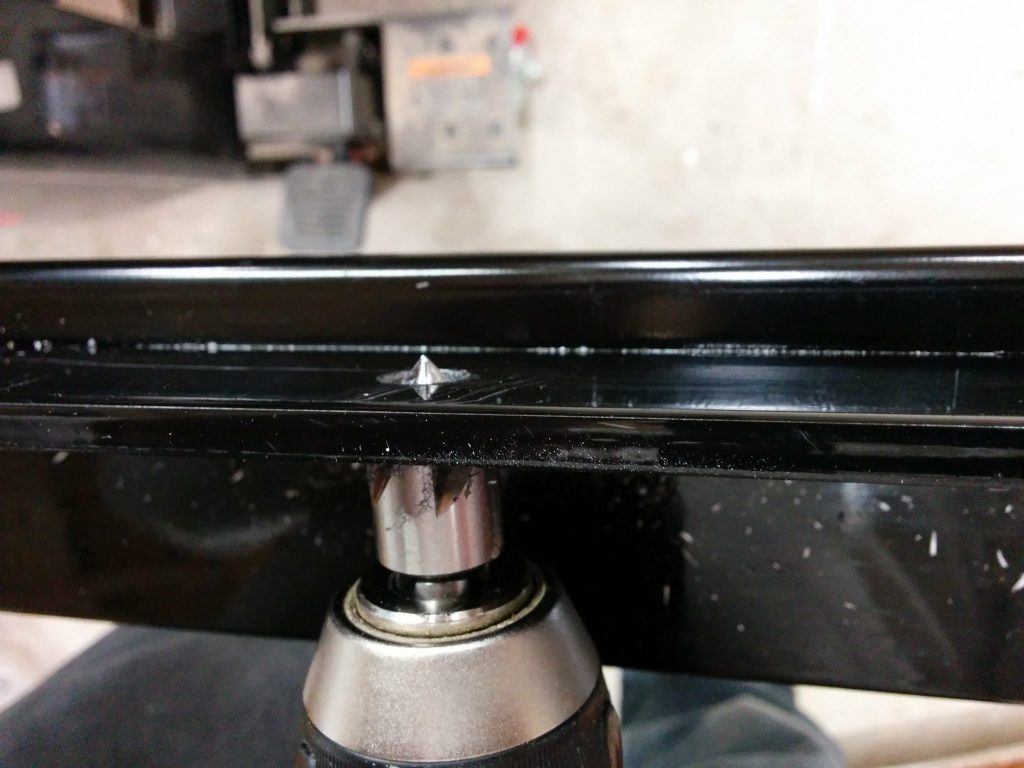
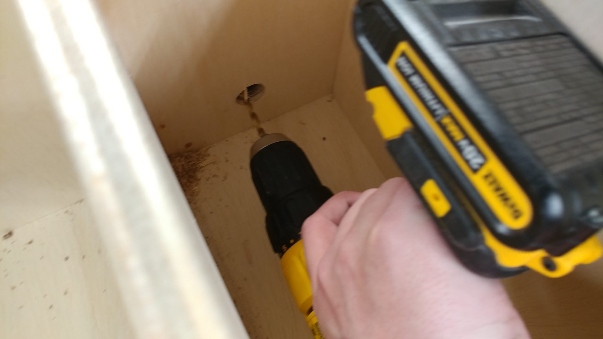
To cut out the holes, I started by drilling a pilot hole through the laminate from the inside of the cabinet.
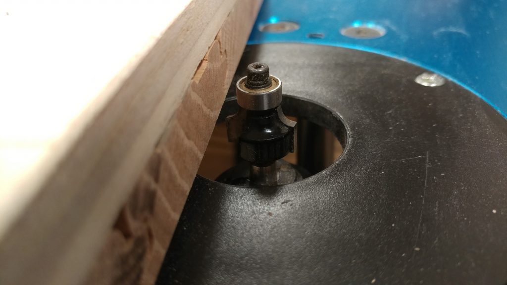
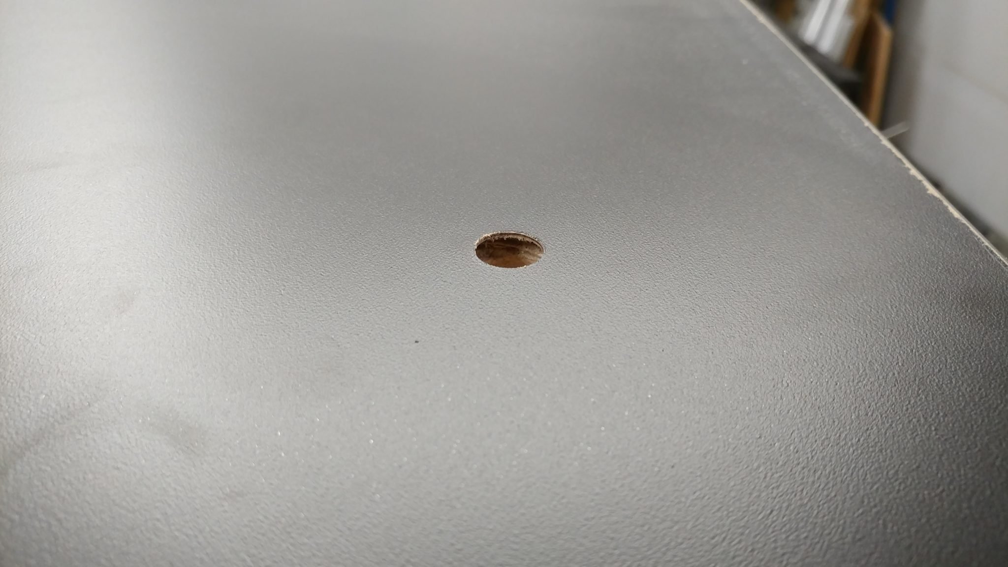
Once the pilot holes were drilled, I went to the outside and made the hole bigger using a step bit.
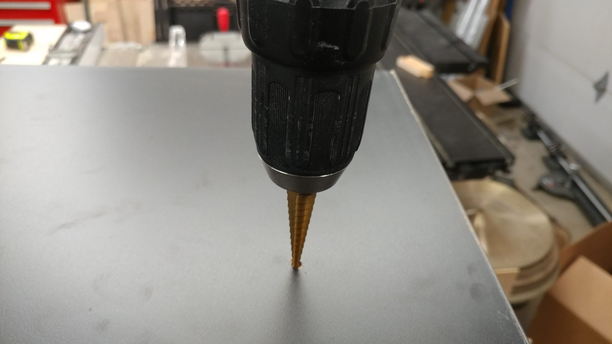
I just need the hole big enough to fit my 1/2″ pattern bit into.
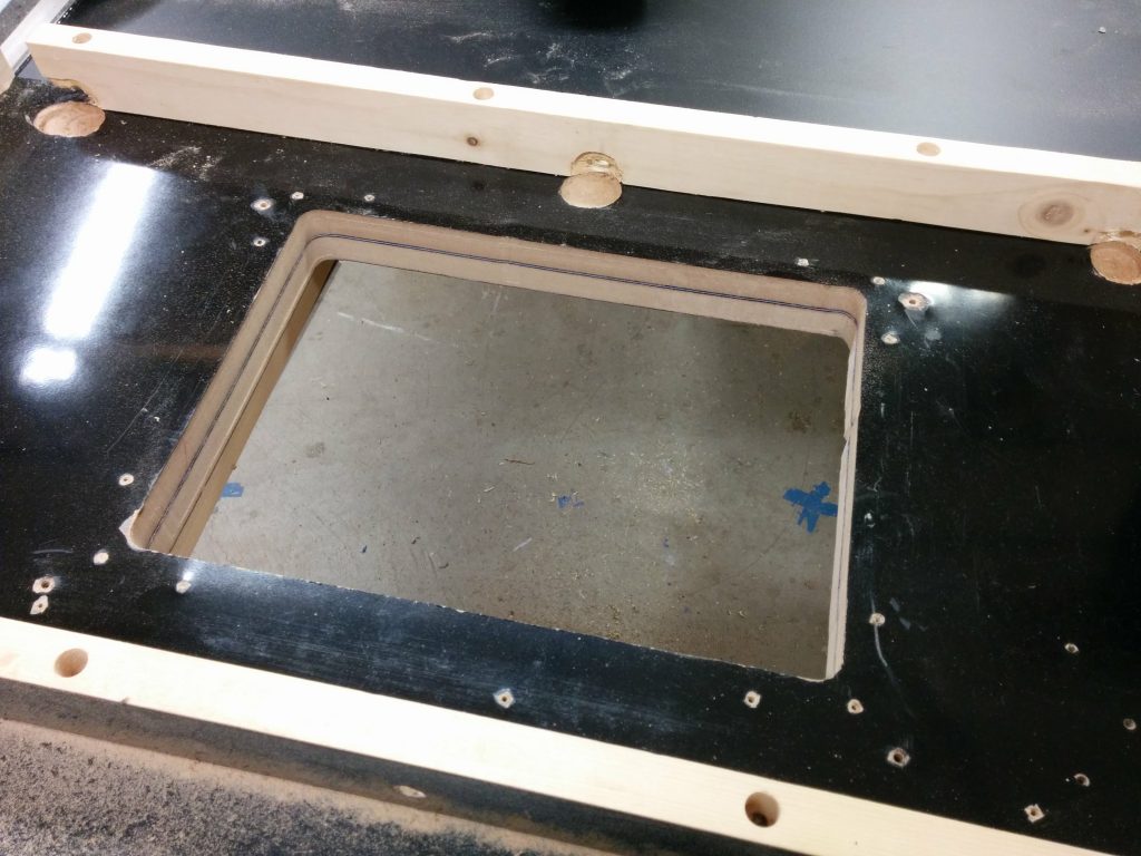
I use the same setup as I used to trim the edges of the laminate.
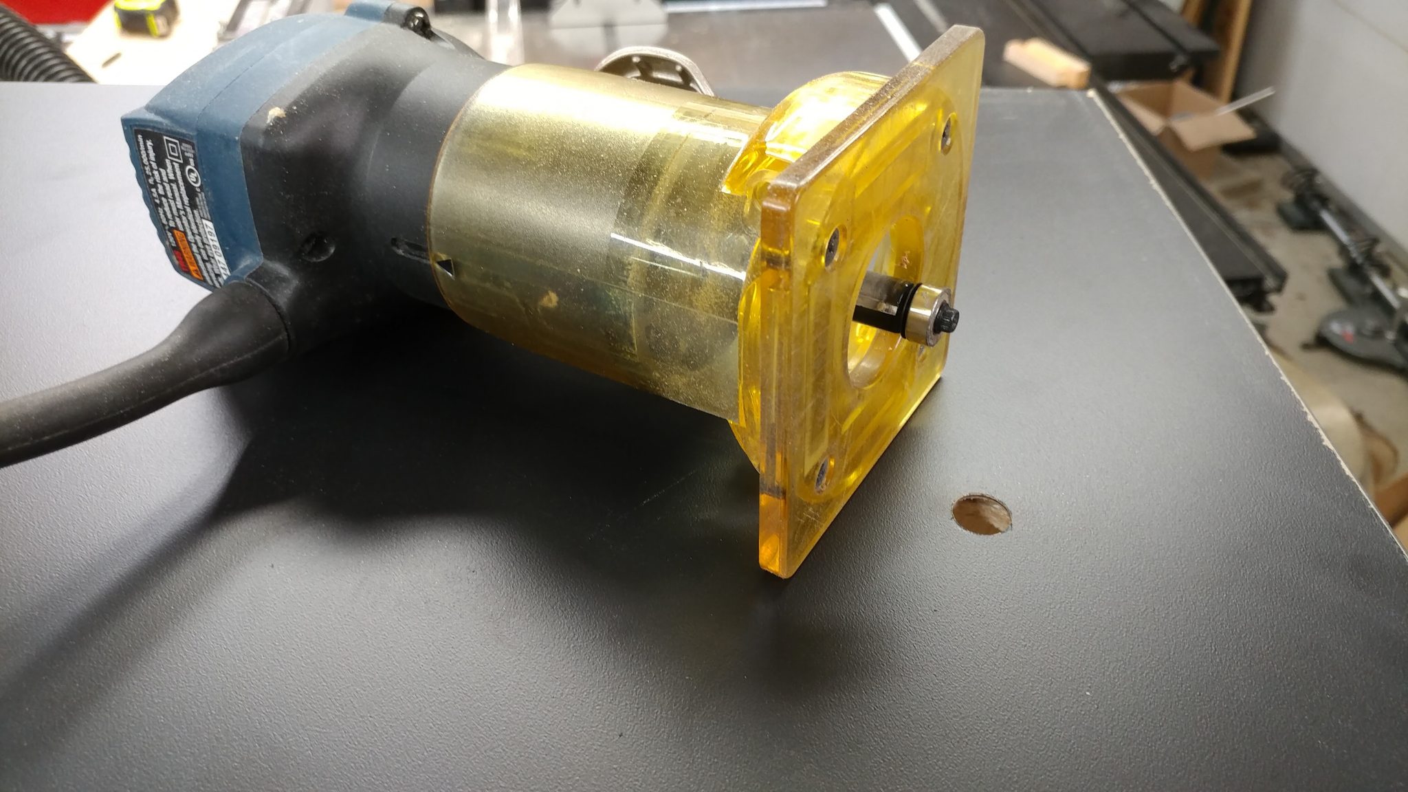
I do this for both holes.
I use the same technique to cut out the openings in the laminate on the front.
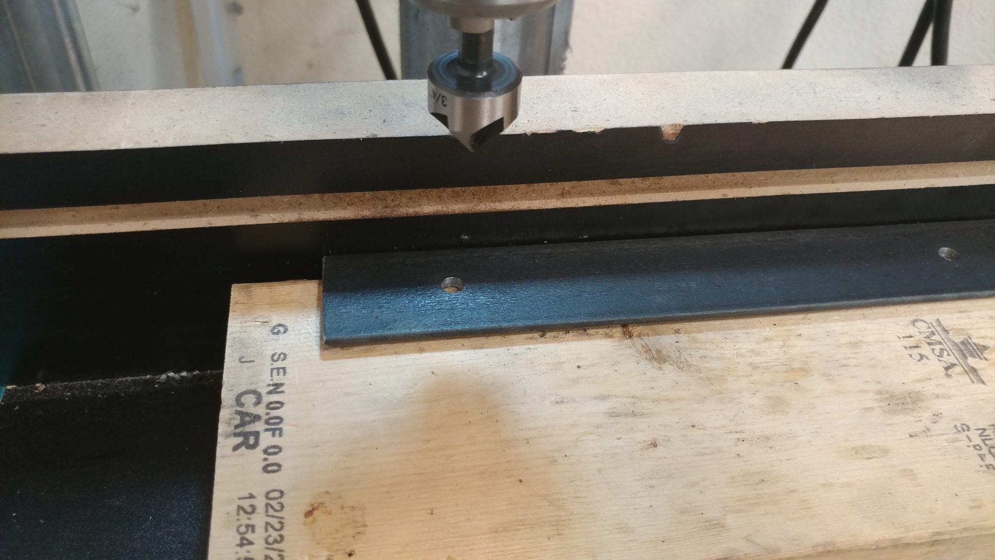
I marked the center of the main door and drilled a 3″ hole in it. This will be for the adjustable air vent.
I attached the laminate to the face of the main drawer…
…to the face of the bit storage drawers…
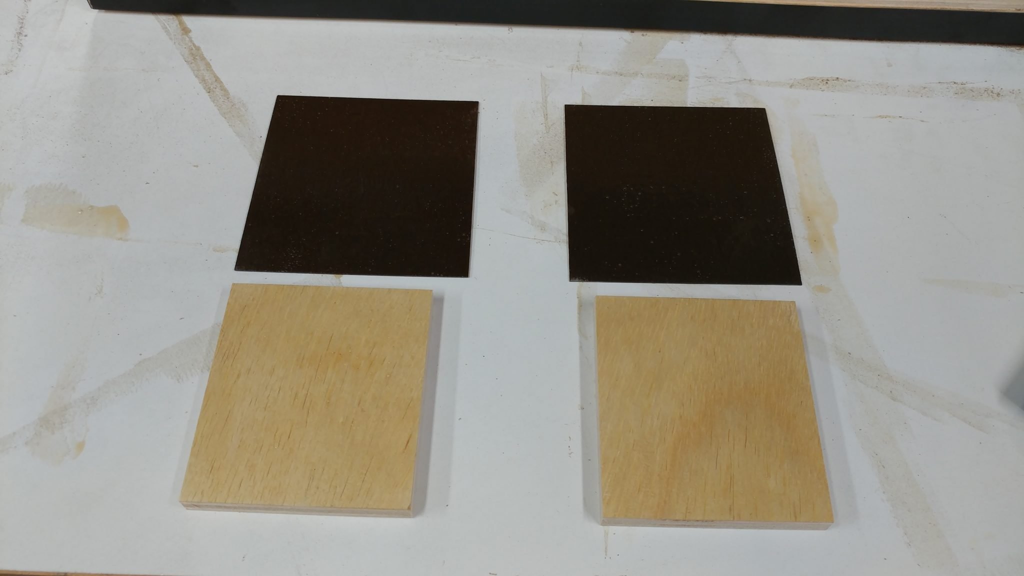
…and the main drawer.
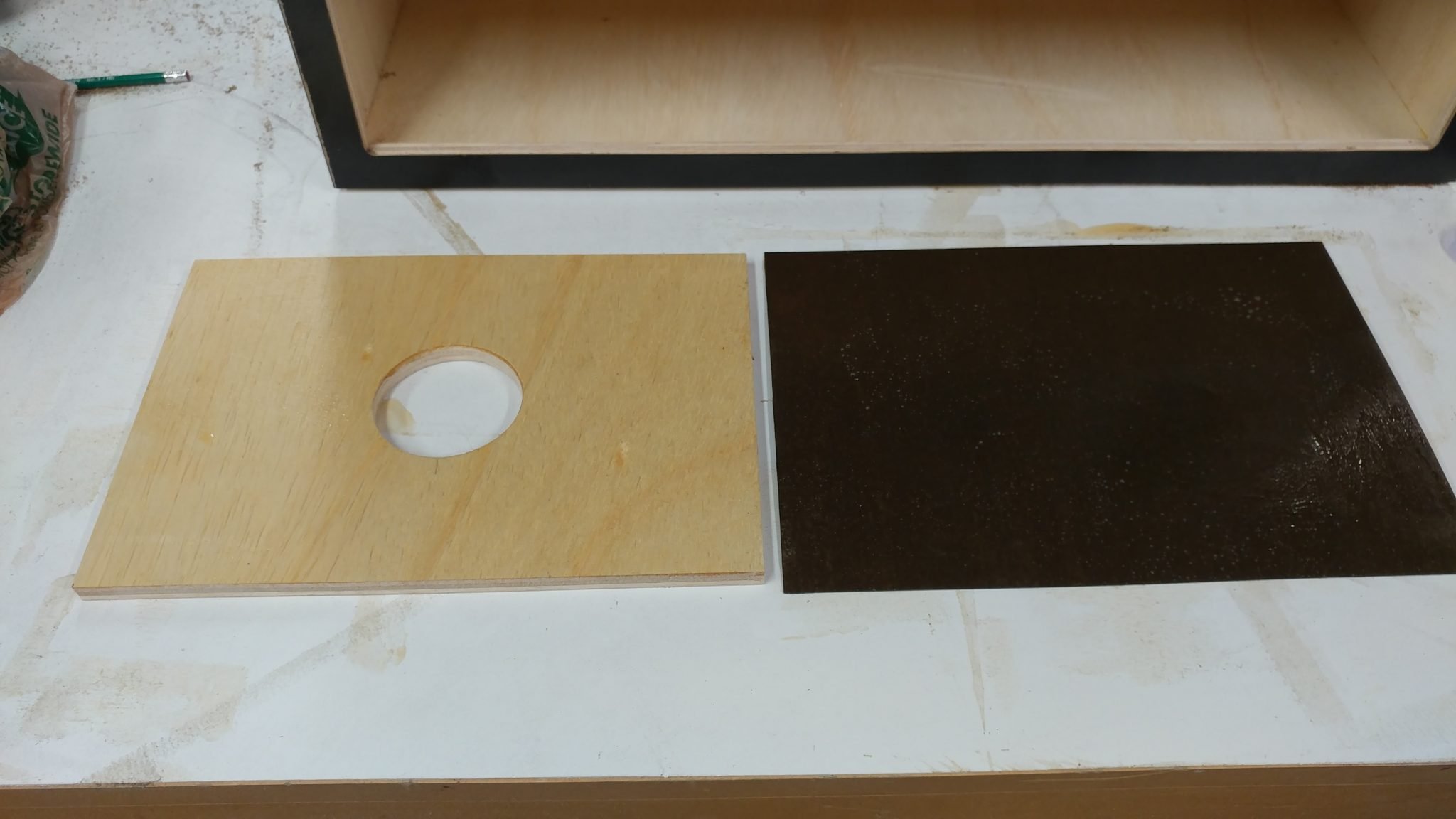
All of the pieces have had the laminate attached and the hole cut out.
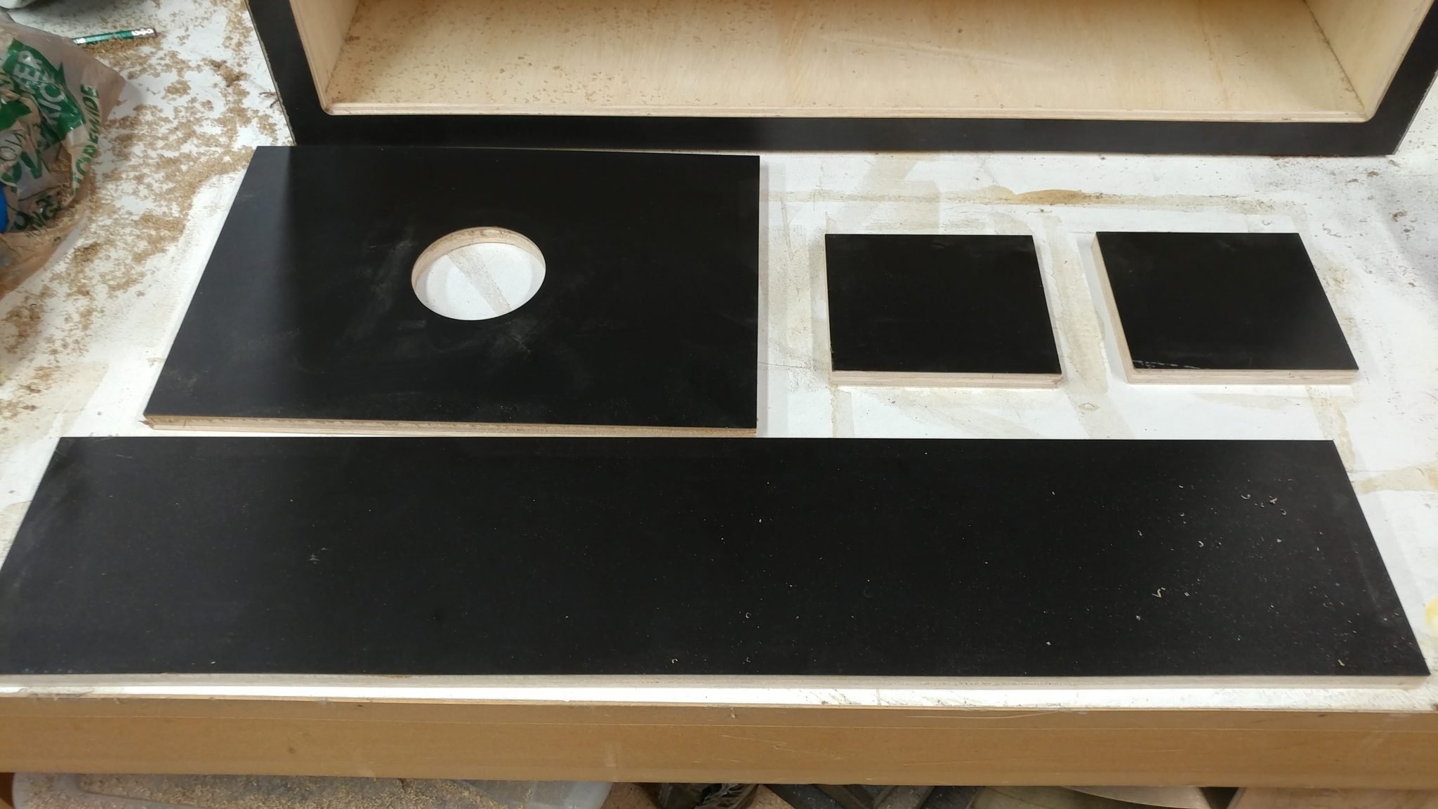
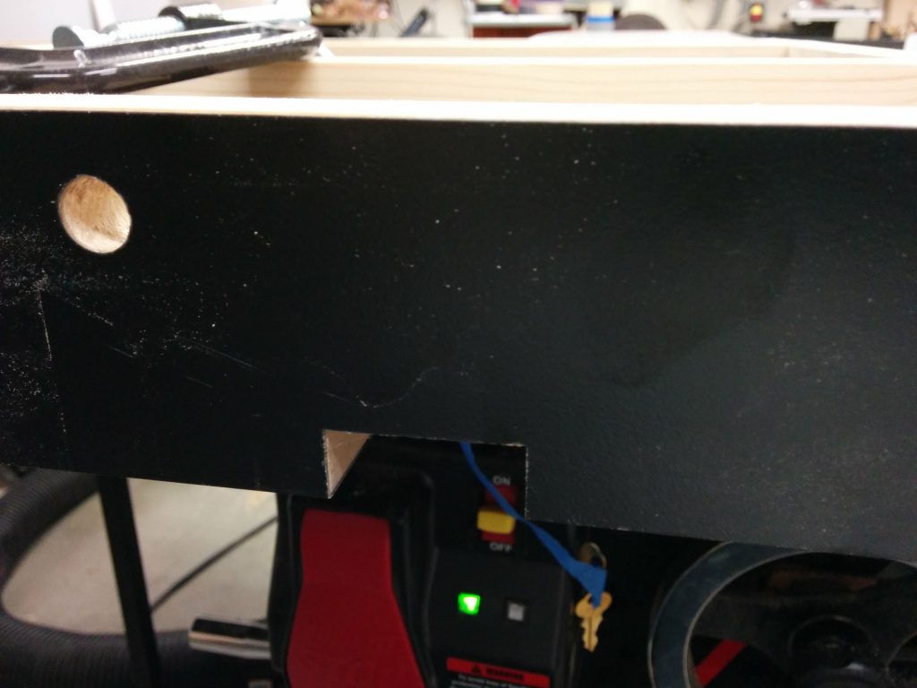
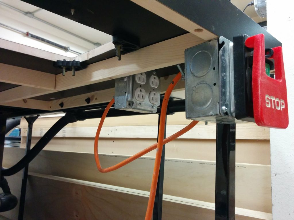
Except for one. I still need to make the door for the electrical. This is going to have the main On/Off paddle in the face of it so I’ll need to cut out the opening for that. This is the electrical box for the paddle.

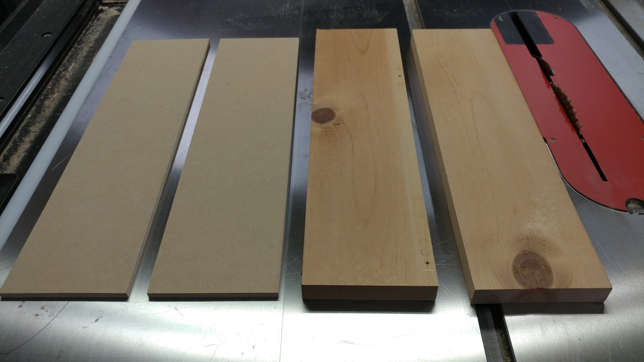
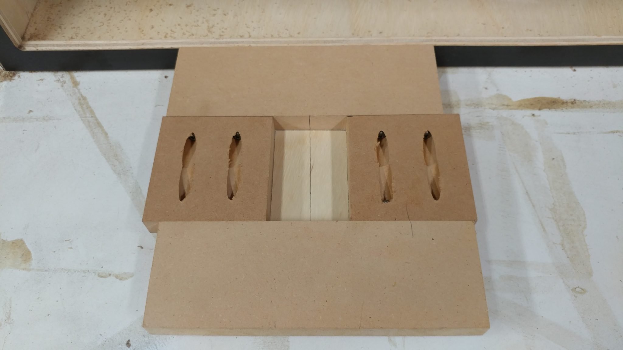
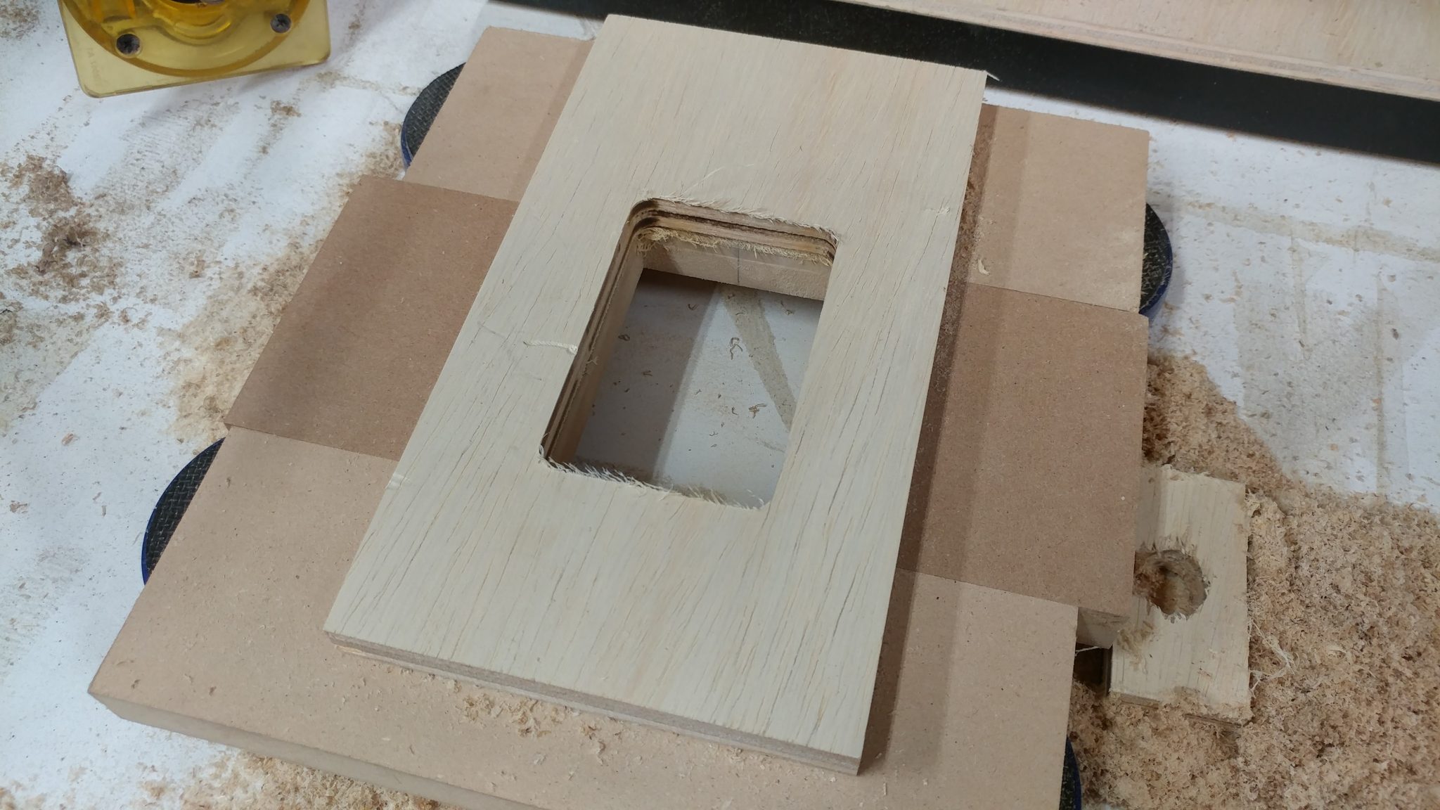
I decided to make a simple routing template using some scrap MDF.
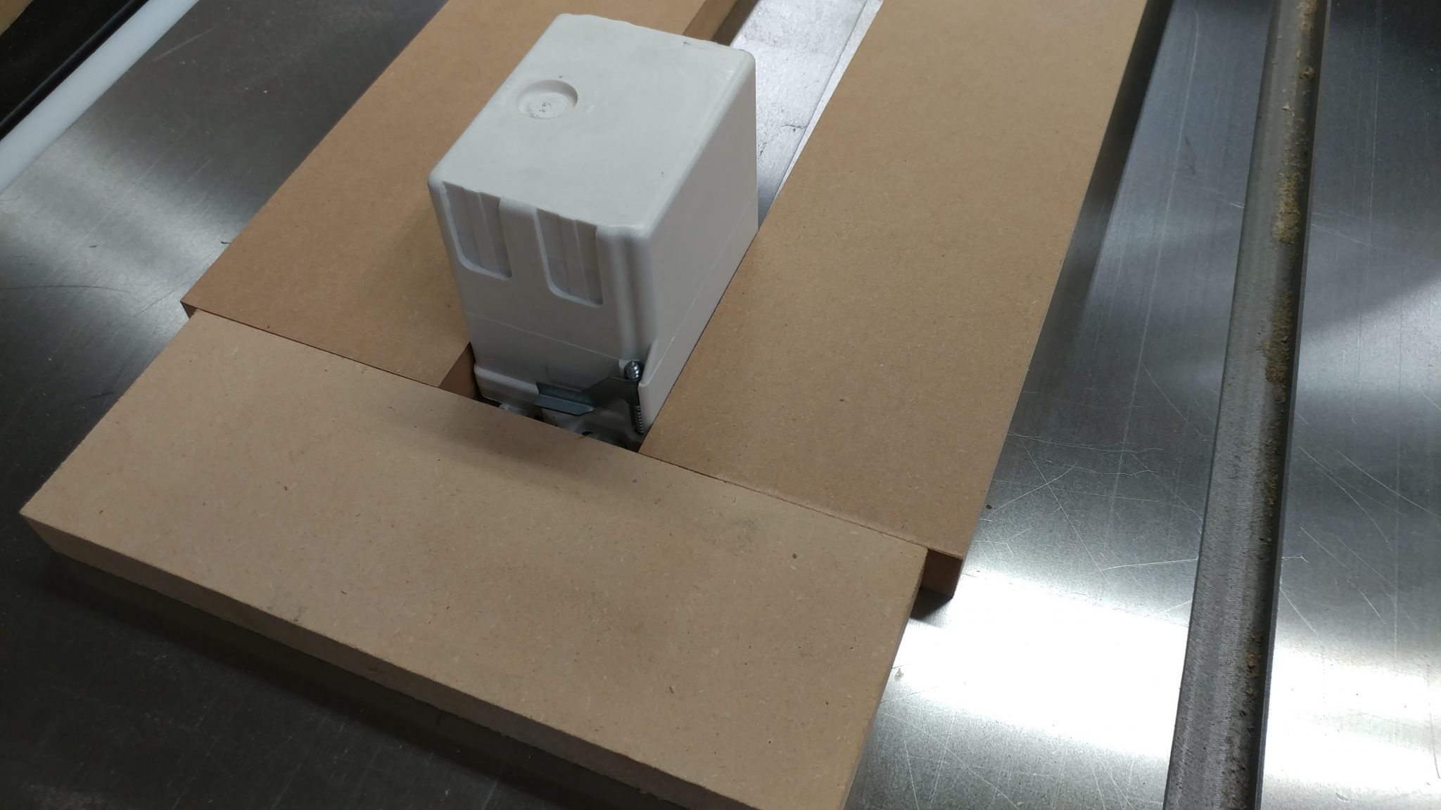
I attached the two side pieces to one of the ends using pocket holes.
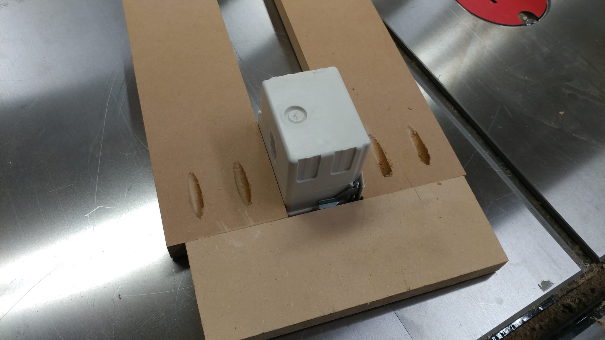
I then used the electrical box to mark and cut the sides down to the proper length.
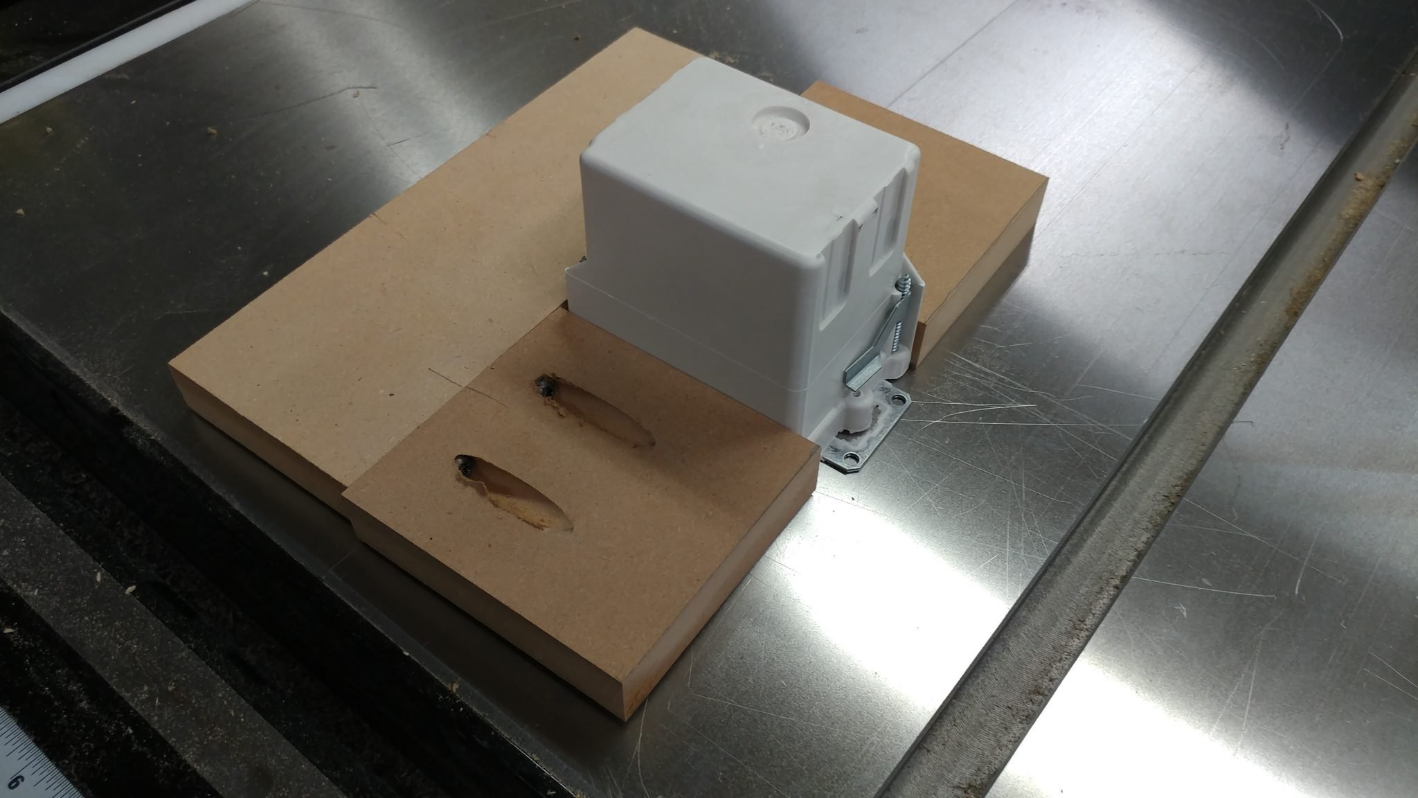
I attached the other end with pocket holes as well.
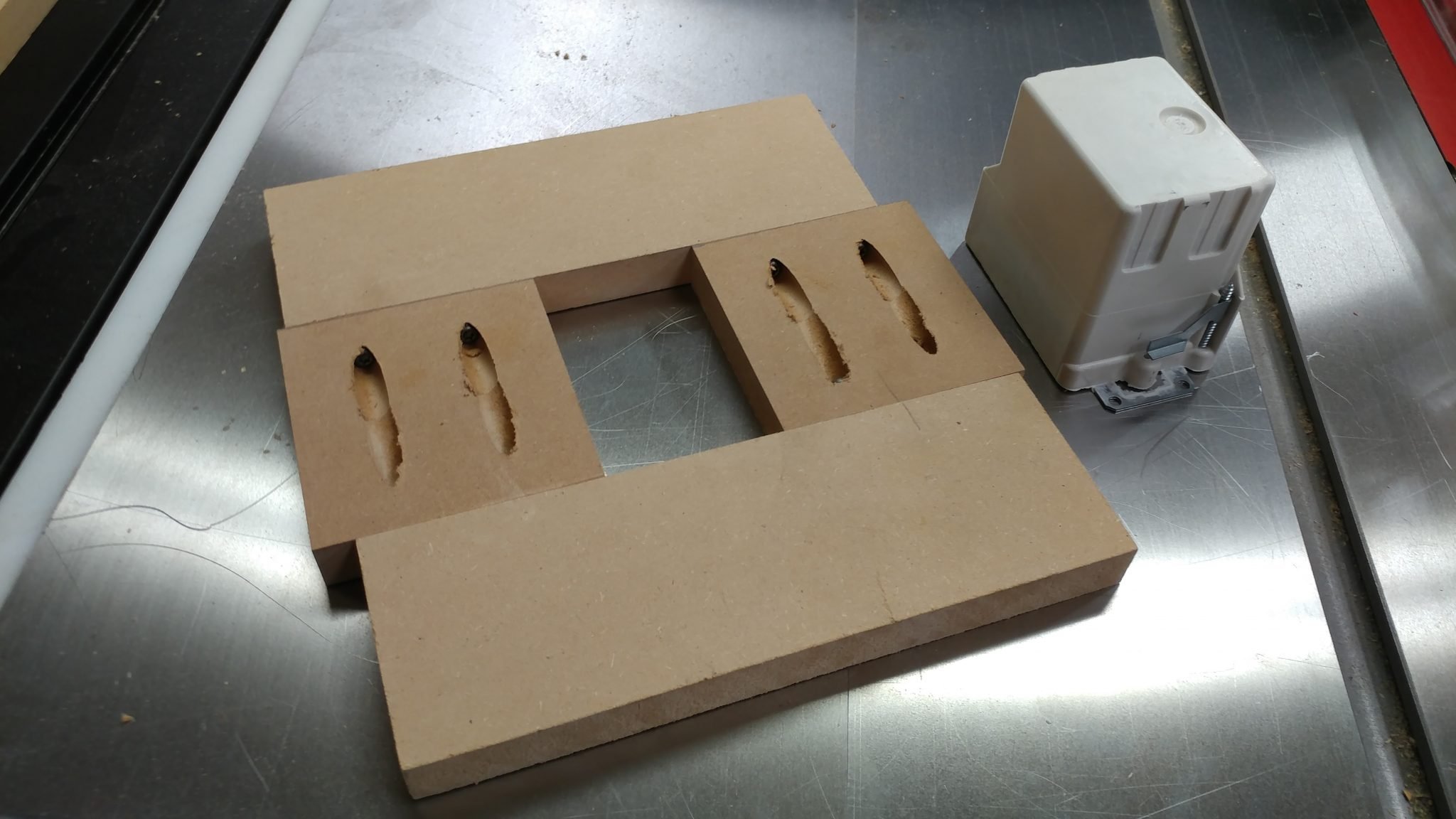
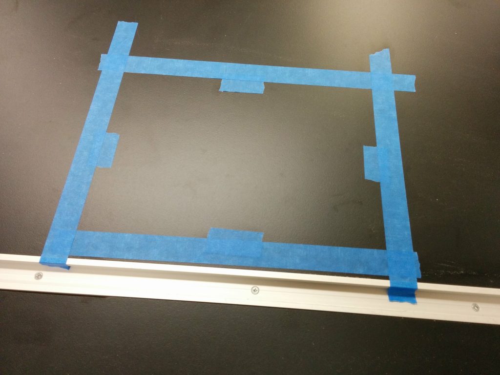
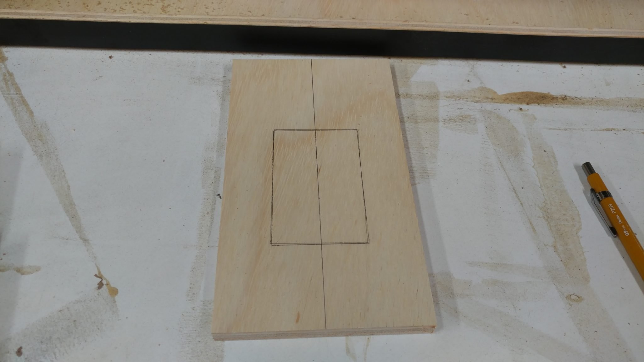
I marked the center of both the door piece and the inside opening of the template.
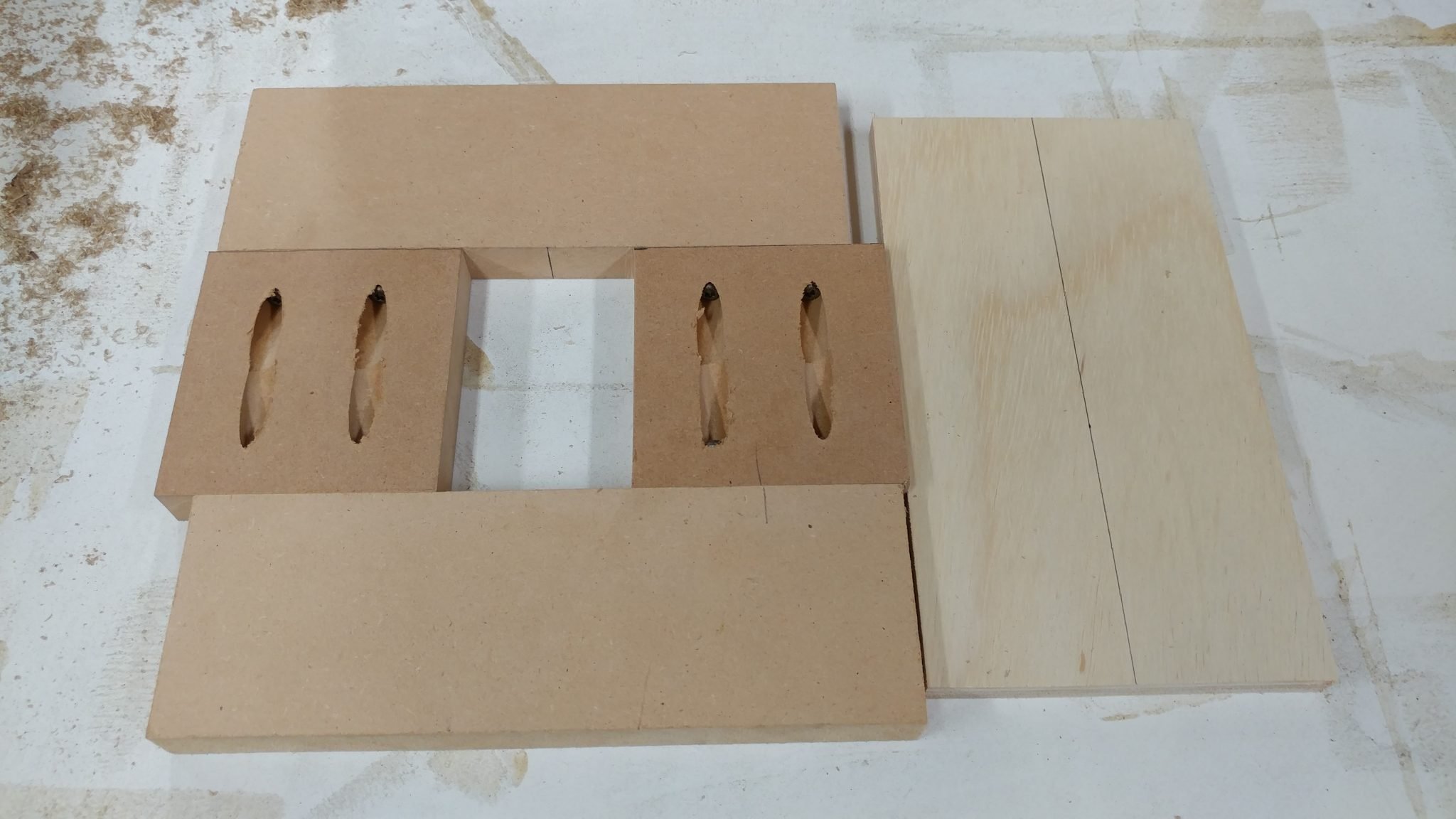
I lined up the routing template and traced around the inside.
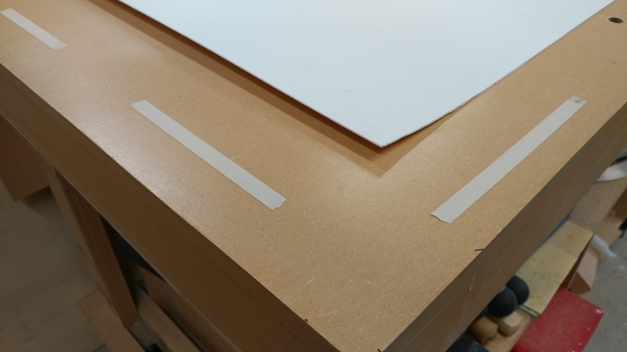
This showed me how it would be placed and allows me to attach some double-sided tape.
Here you can see the double-sided tape.
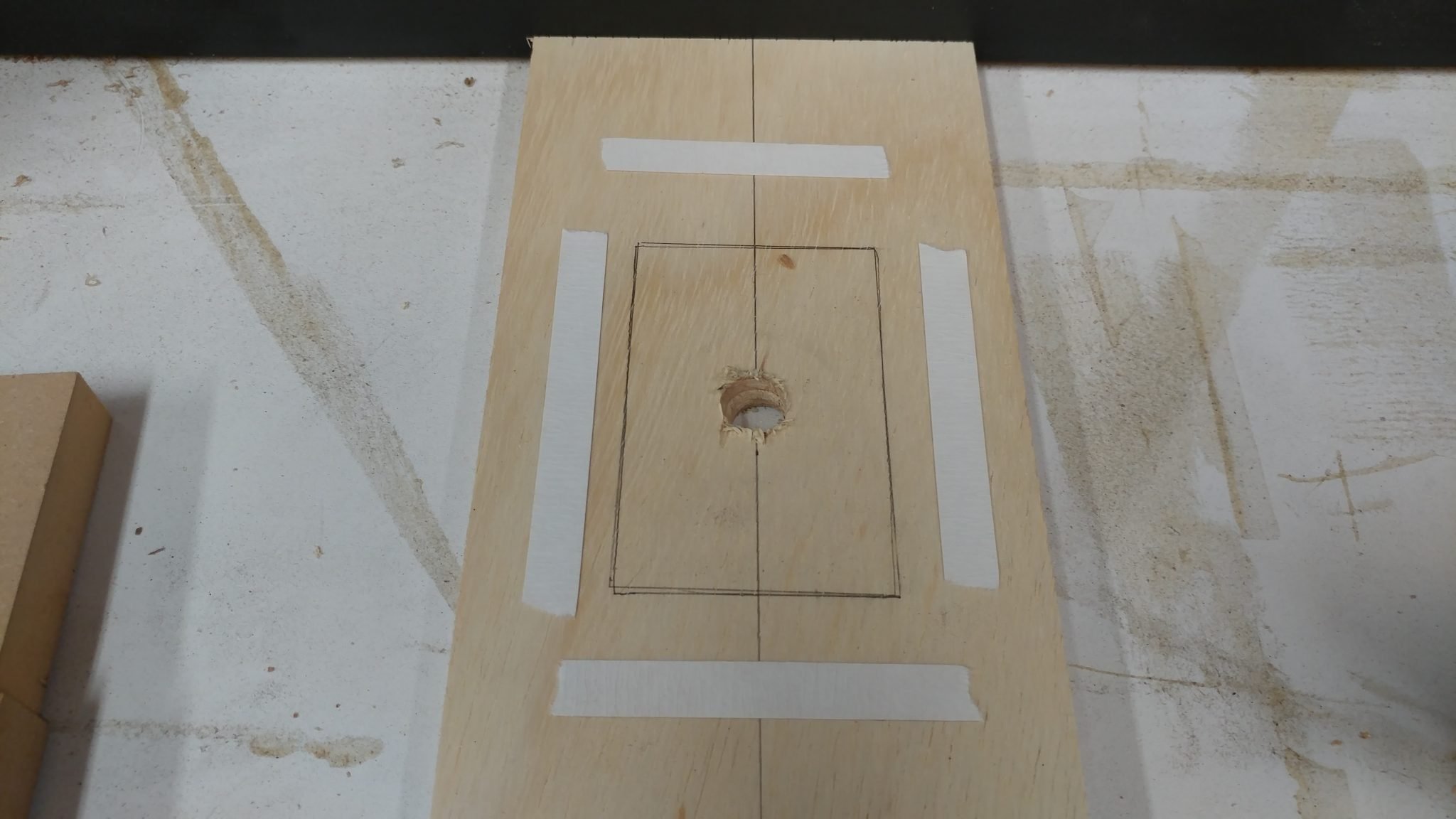
I attach the template then drill a starting hole big enough for the router bit to fit through.
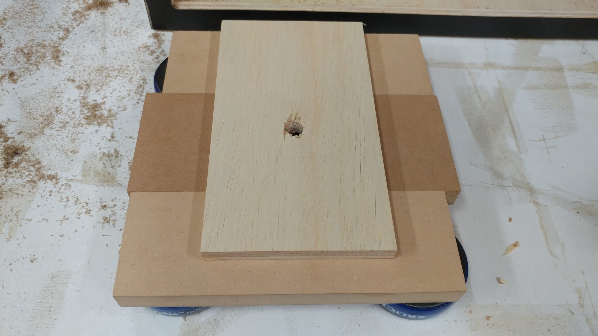
I cut out the opening with the same pattern bit that I’ve been using.
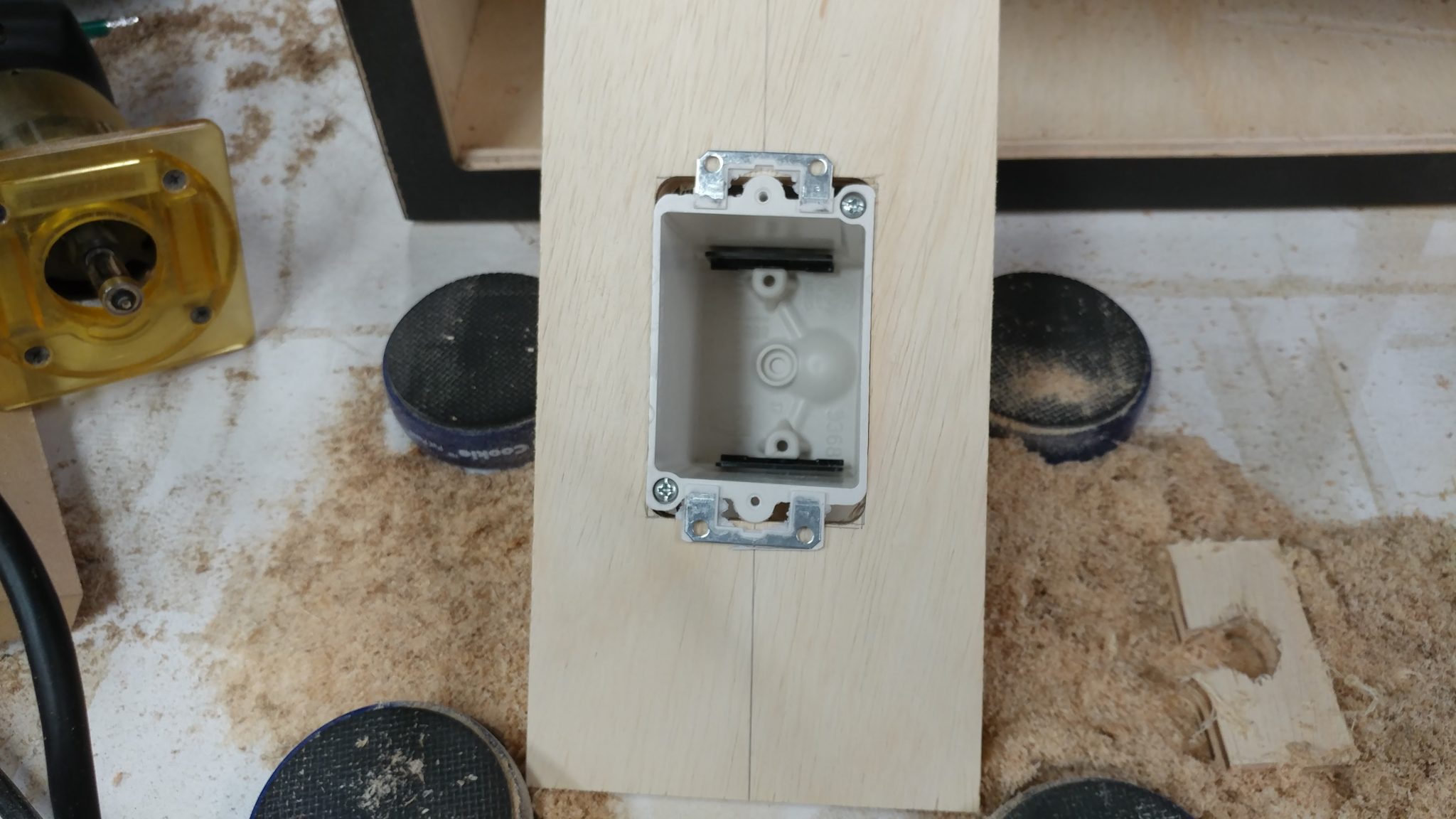
Here you can see how the electrical box fits in place.
I attached and trimmed the laminate like I did for the other pieces.
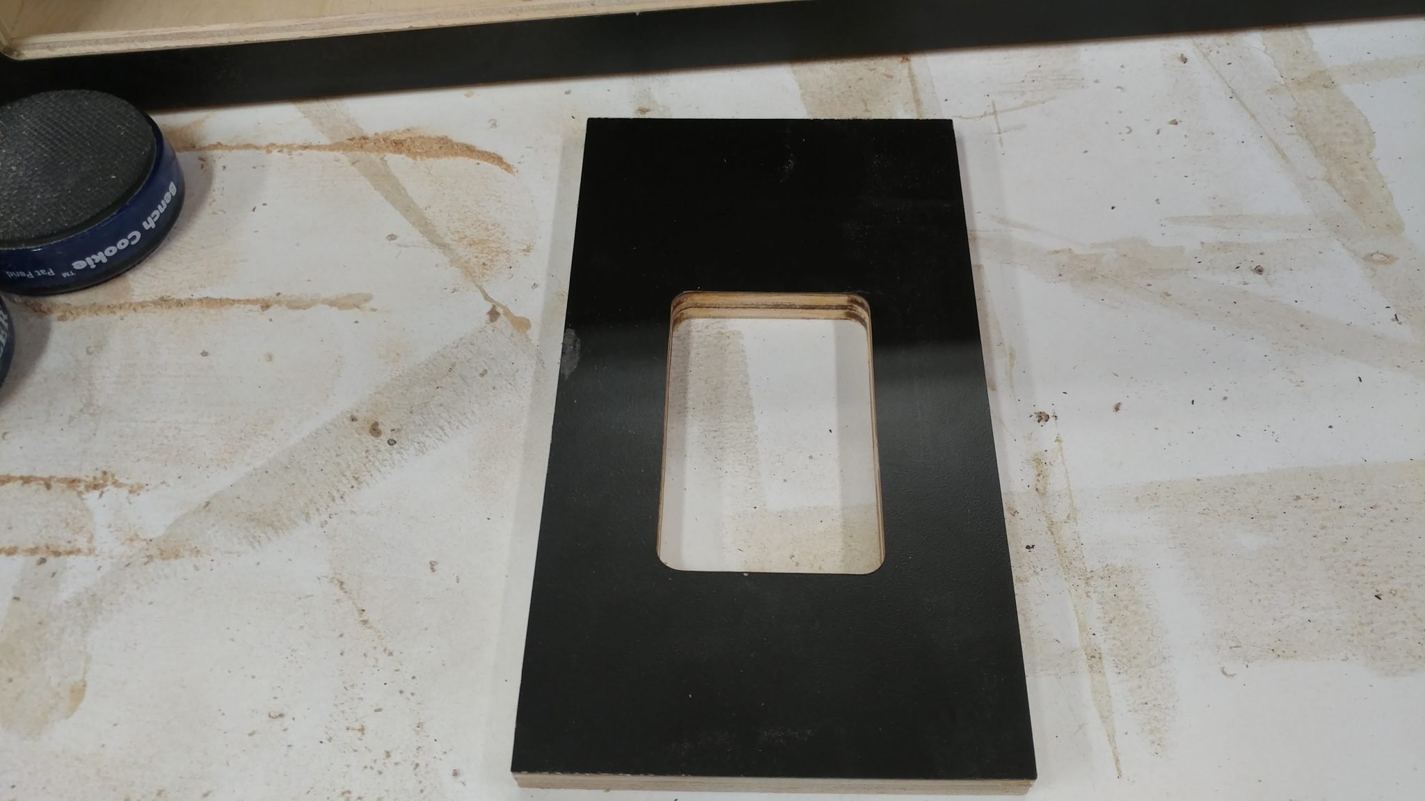
I used the same routing template to cut out the opening for the electrical box that the router will plug into.
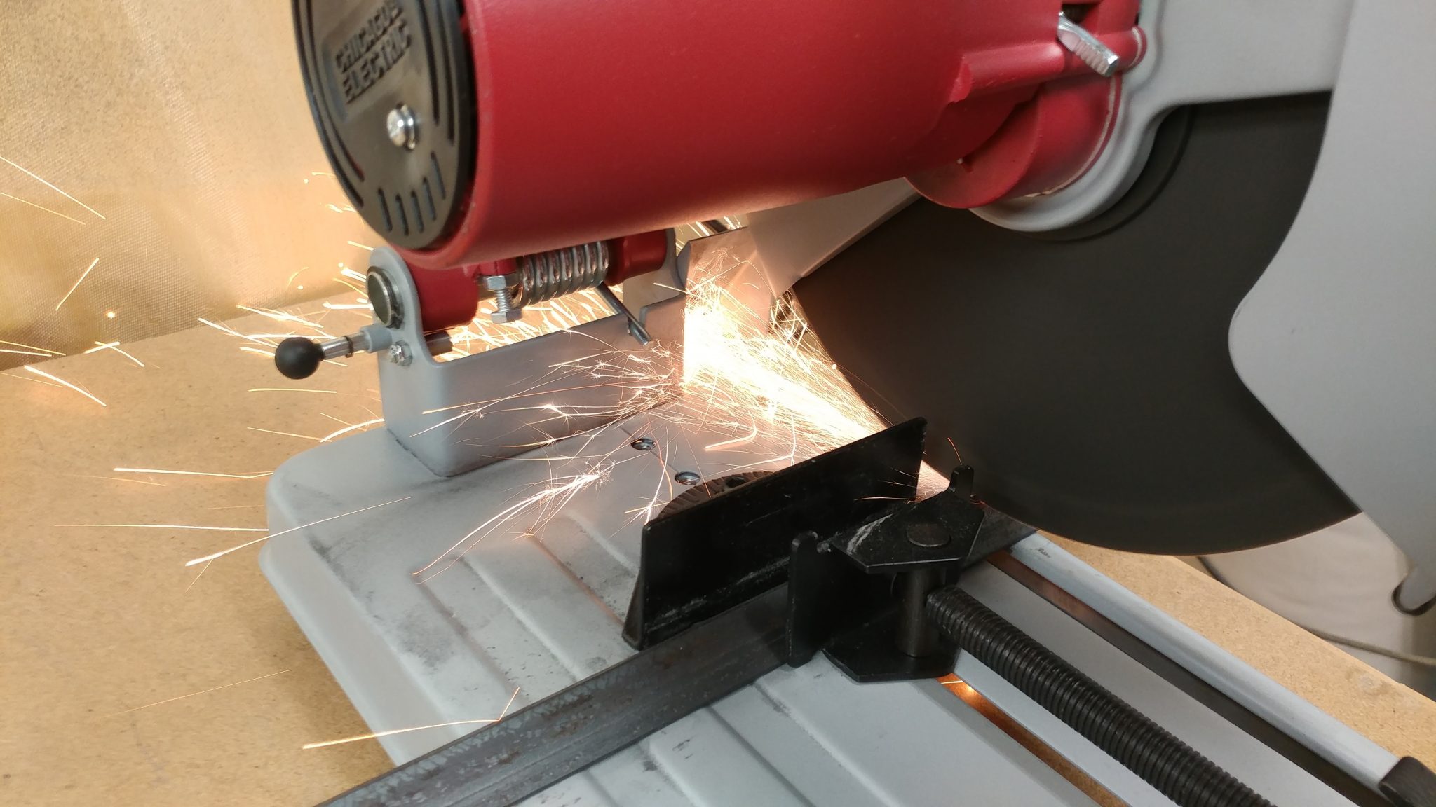
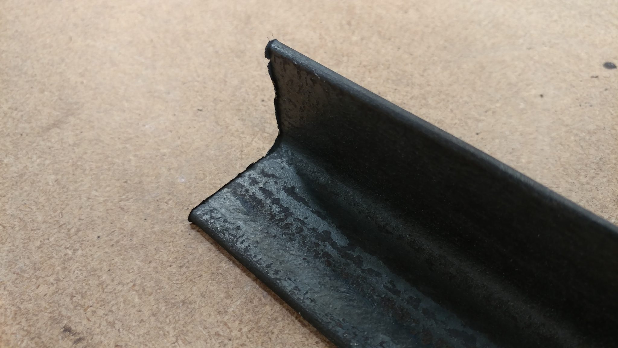
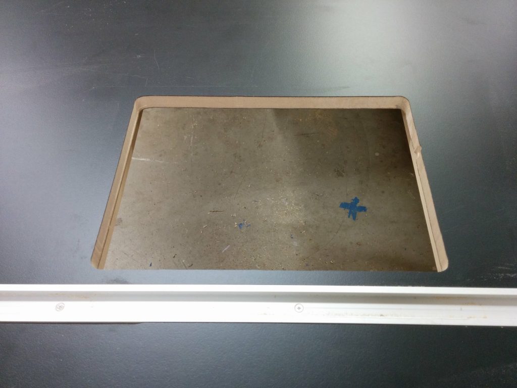
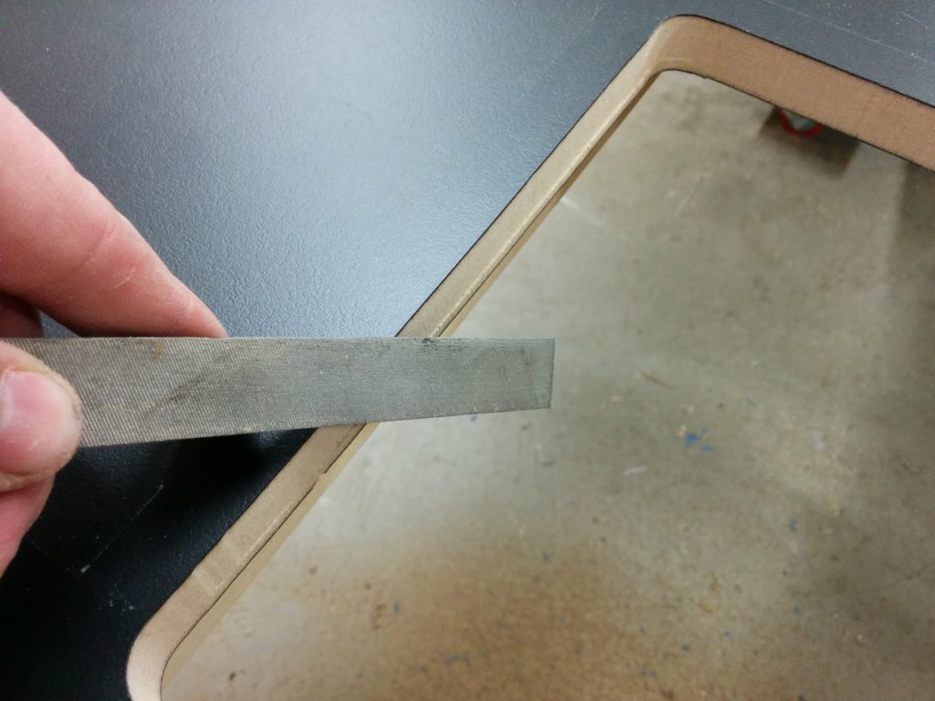
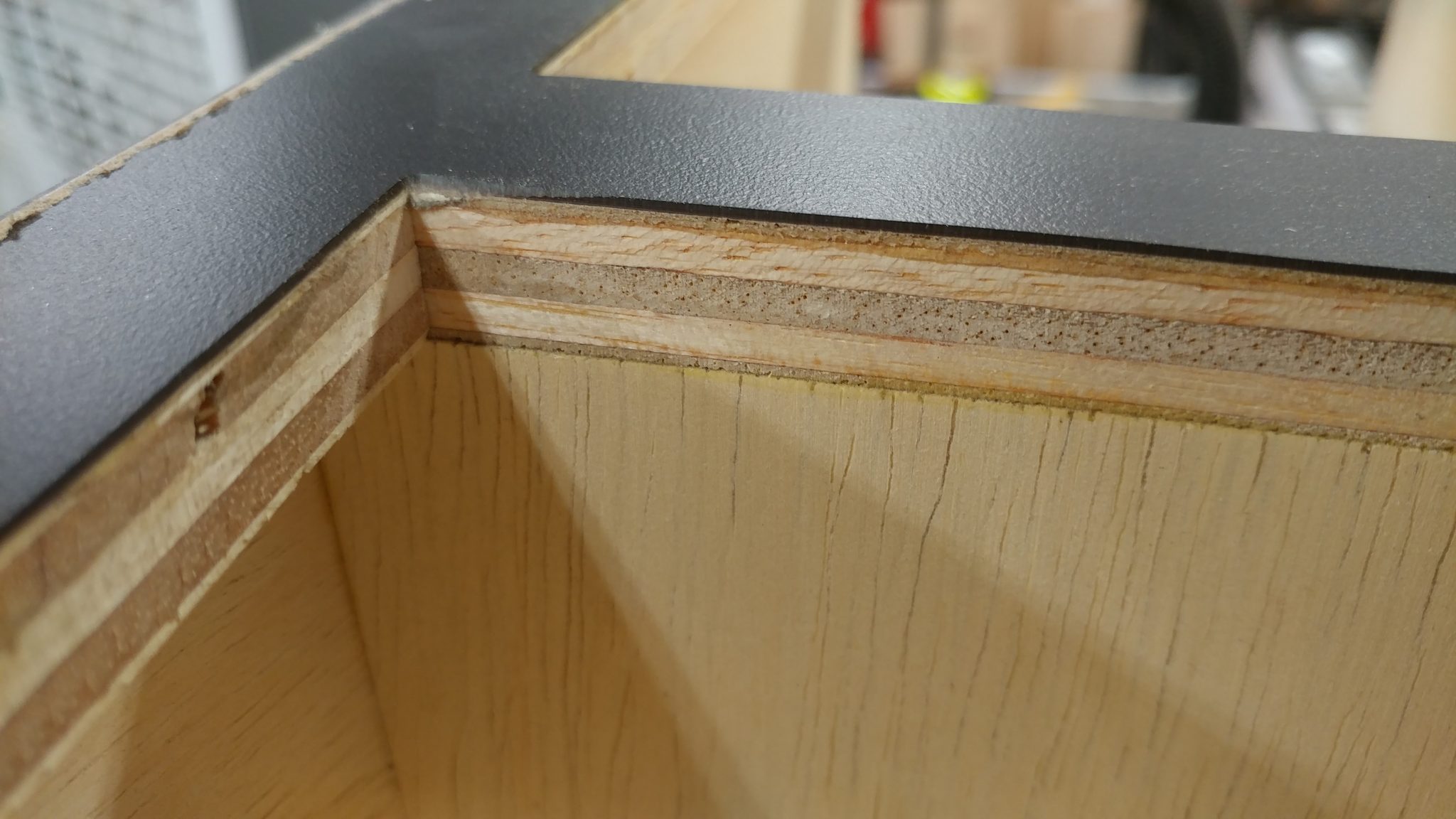
The router bit makes a rounded opening. Although I like the look of it, the openings in the cabinet need to be squared, not rounded.
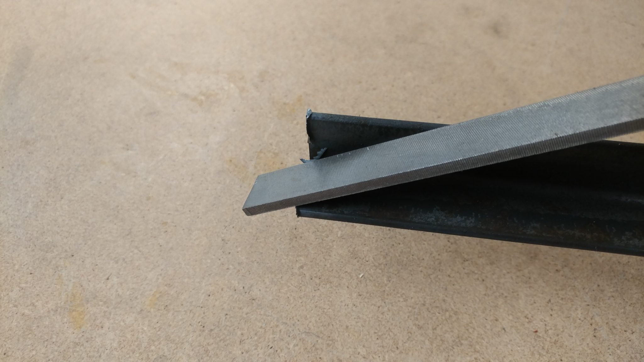
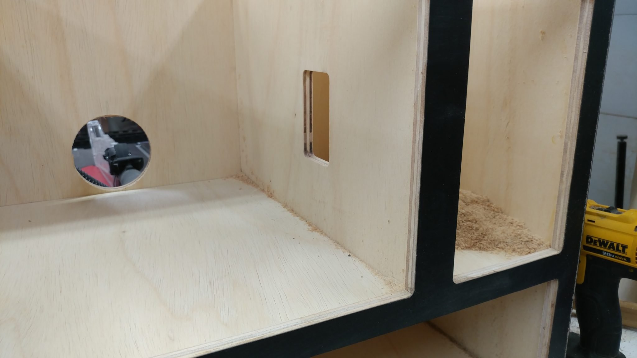
This is easy to fix with a flat file.
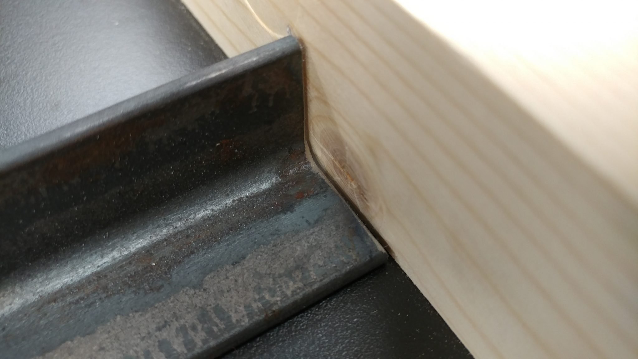
All of the openings have been squared. You can see some residue from the contact adhesive on the corners. I’ll take care of that later.
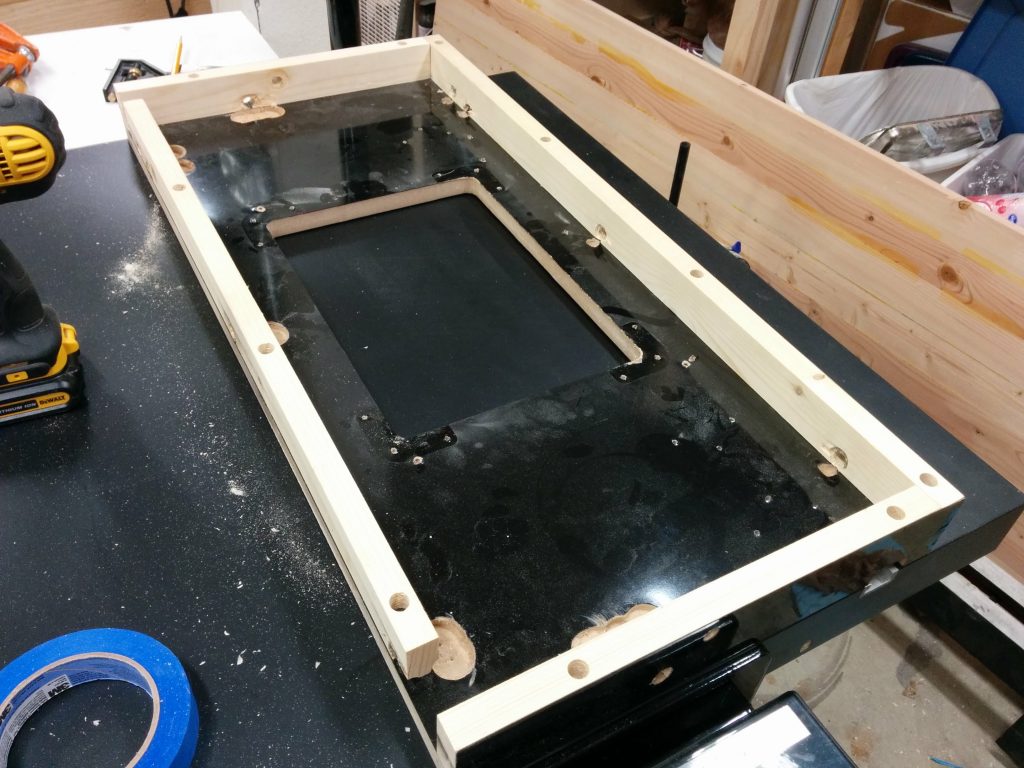
Sealing the doorways
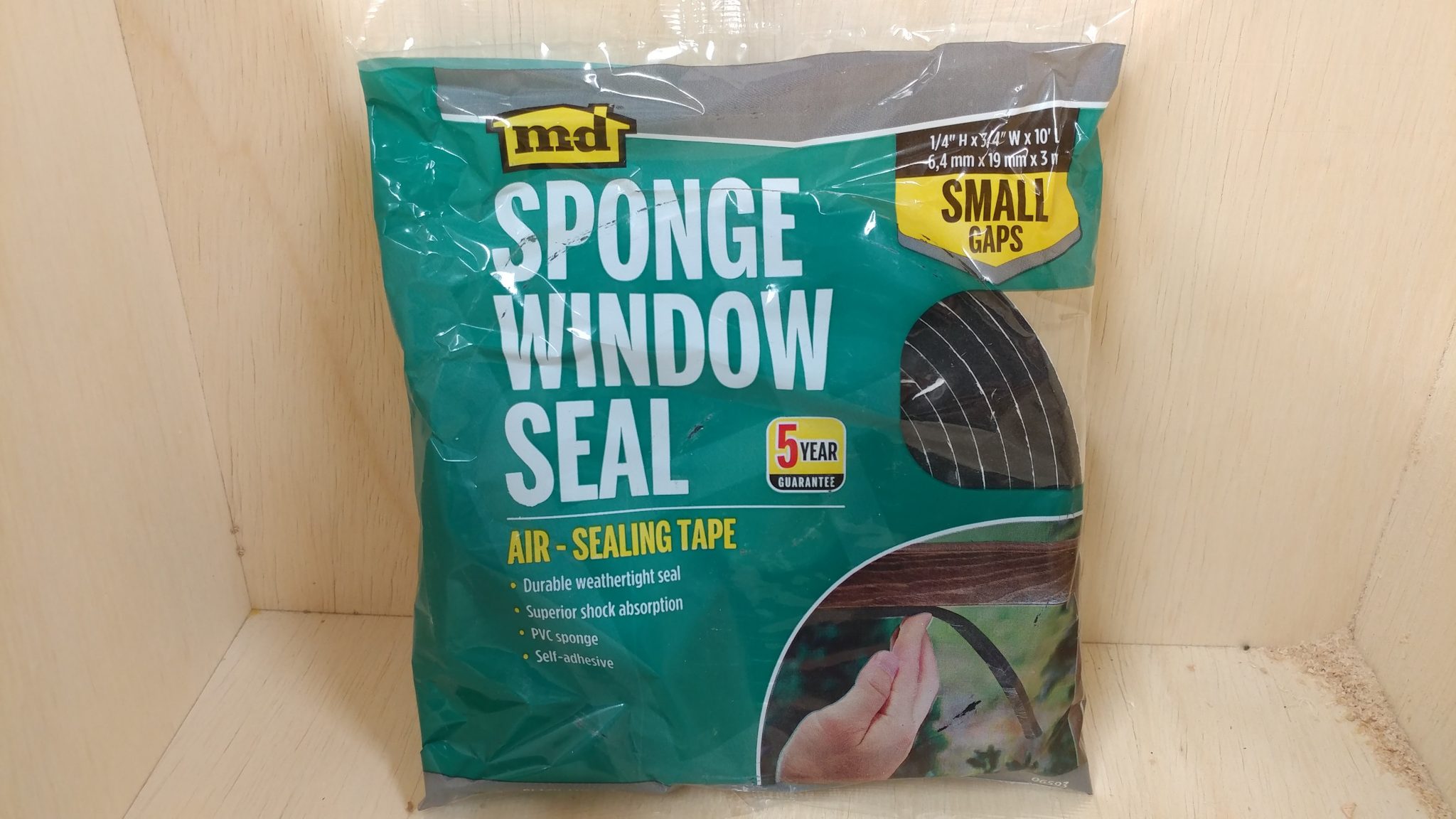
I’m using some sponge window seal to make the doors more airtight.
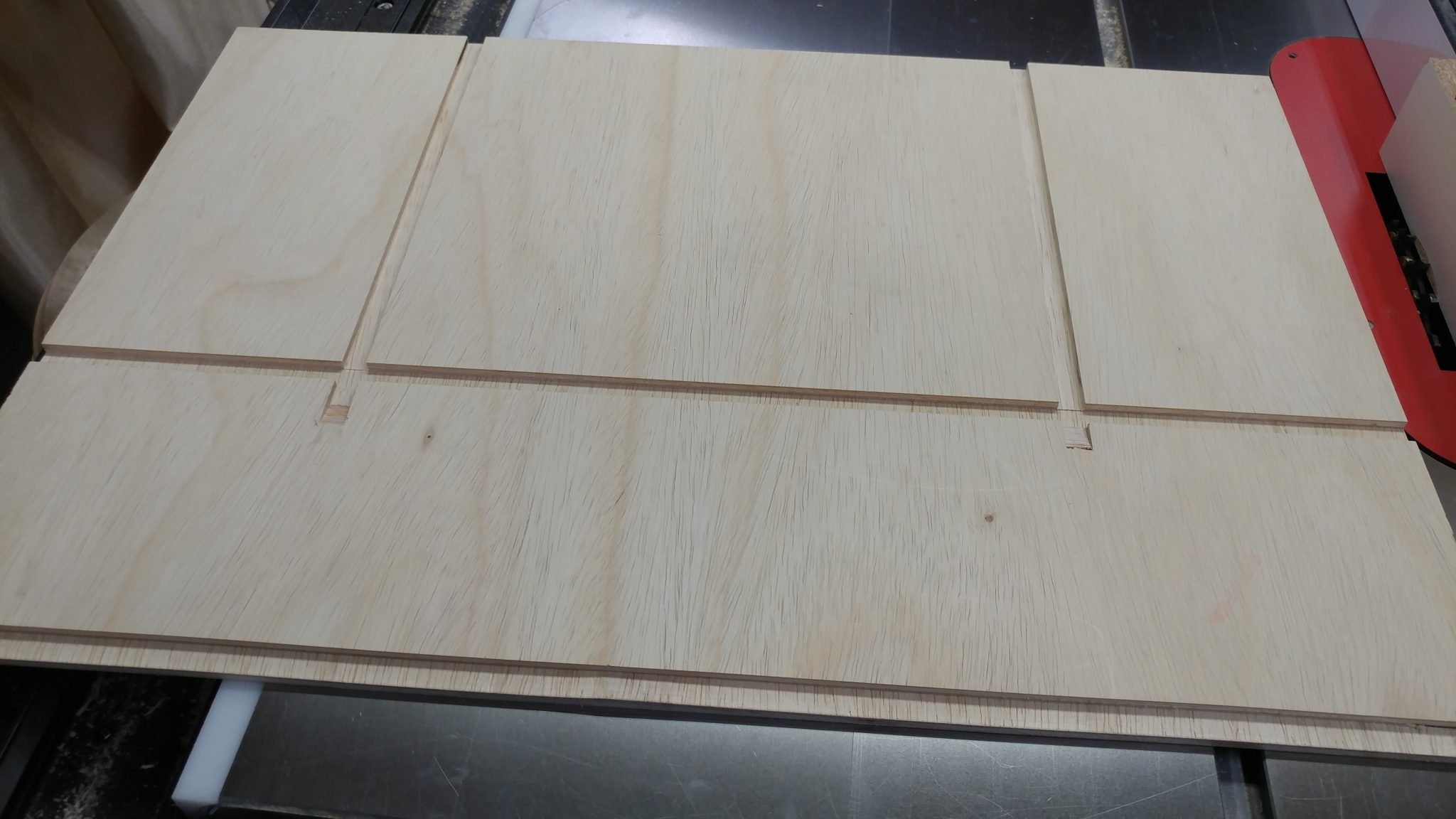
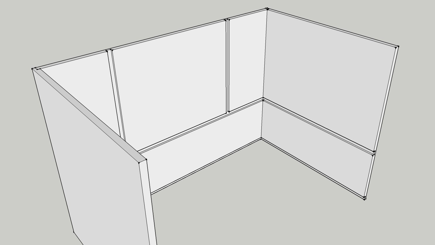
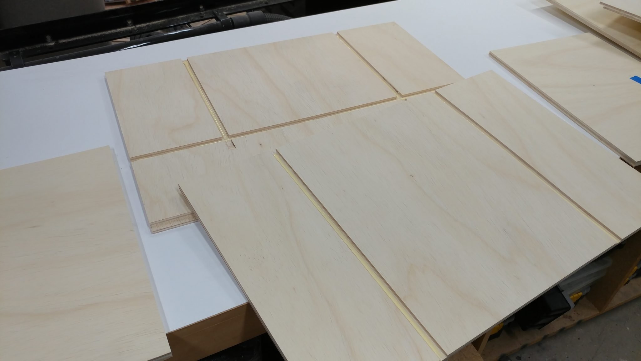
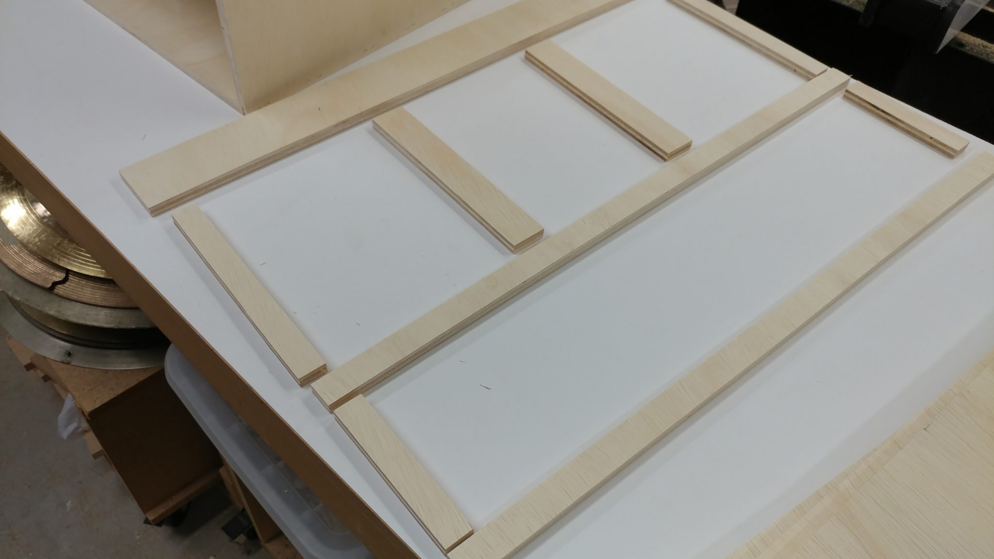
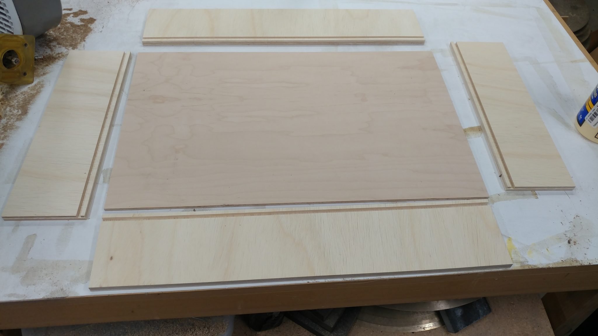
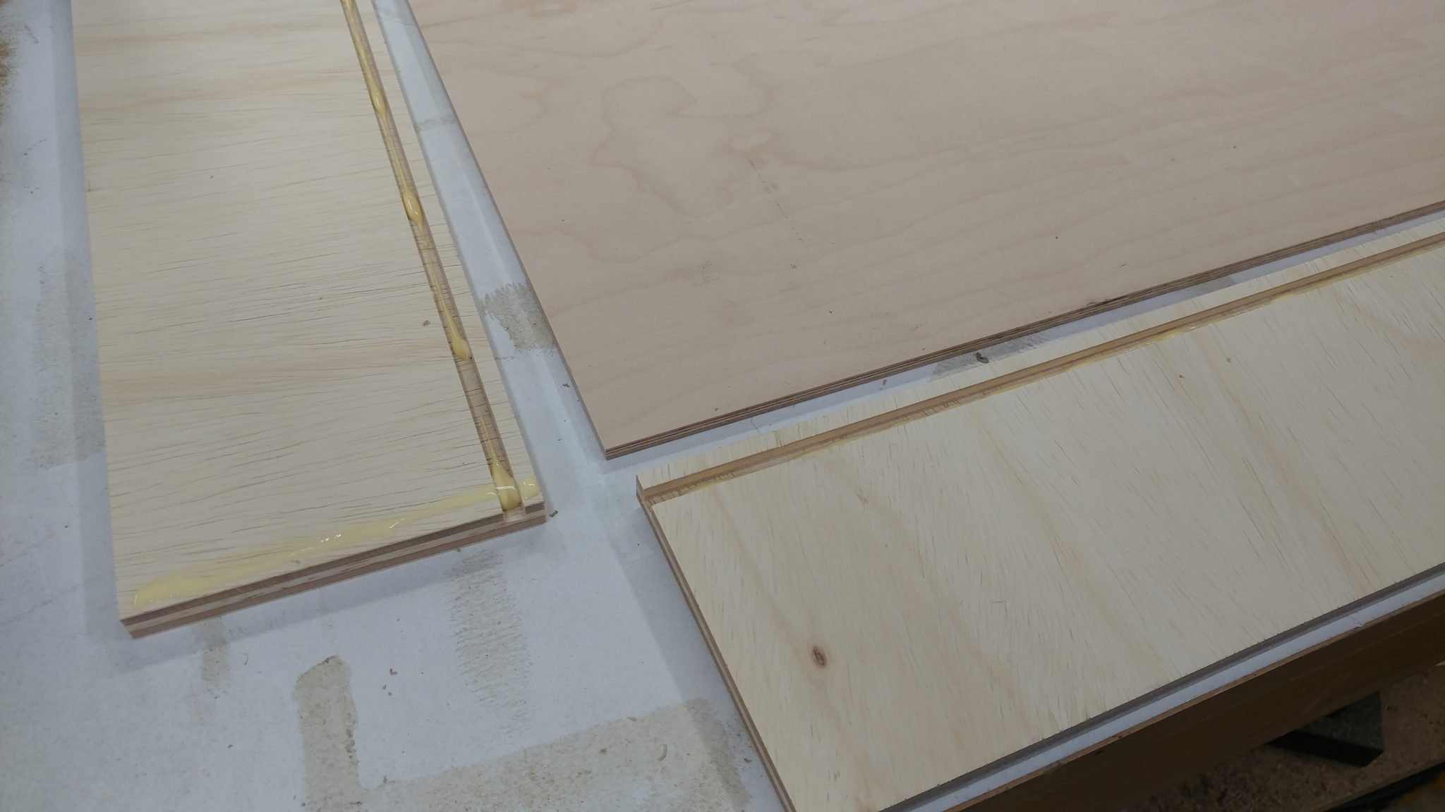
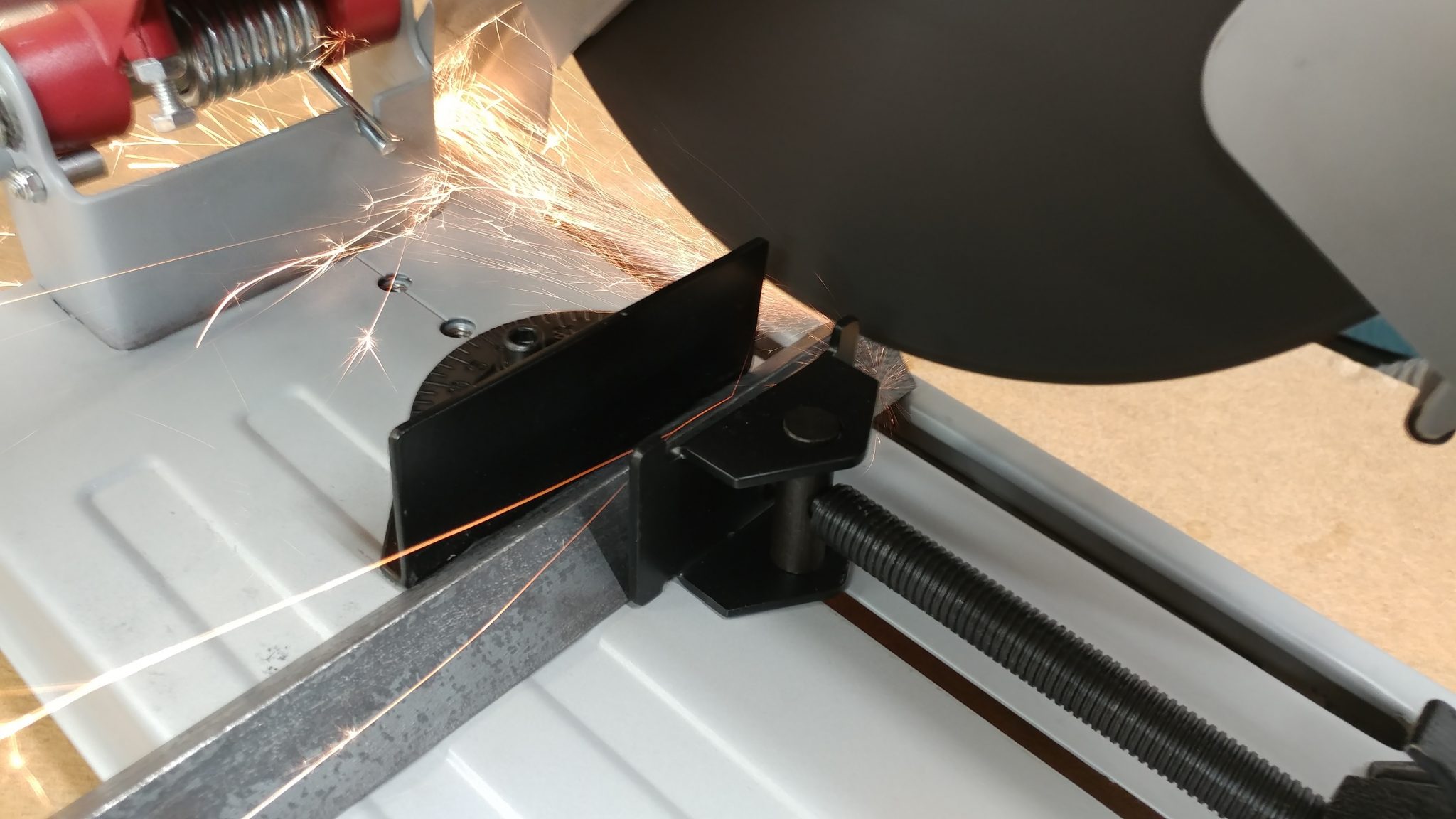
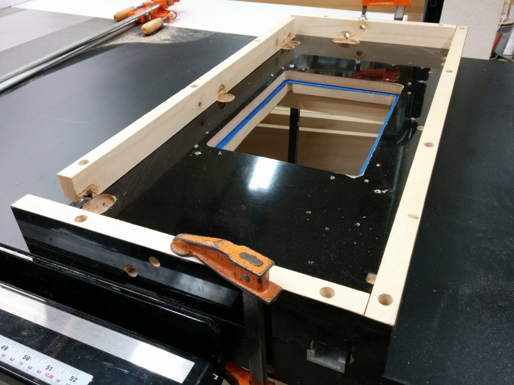
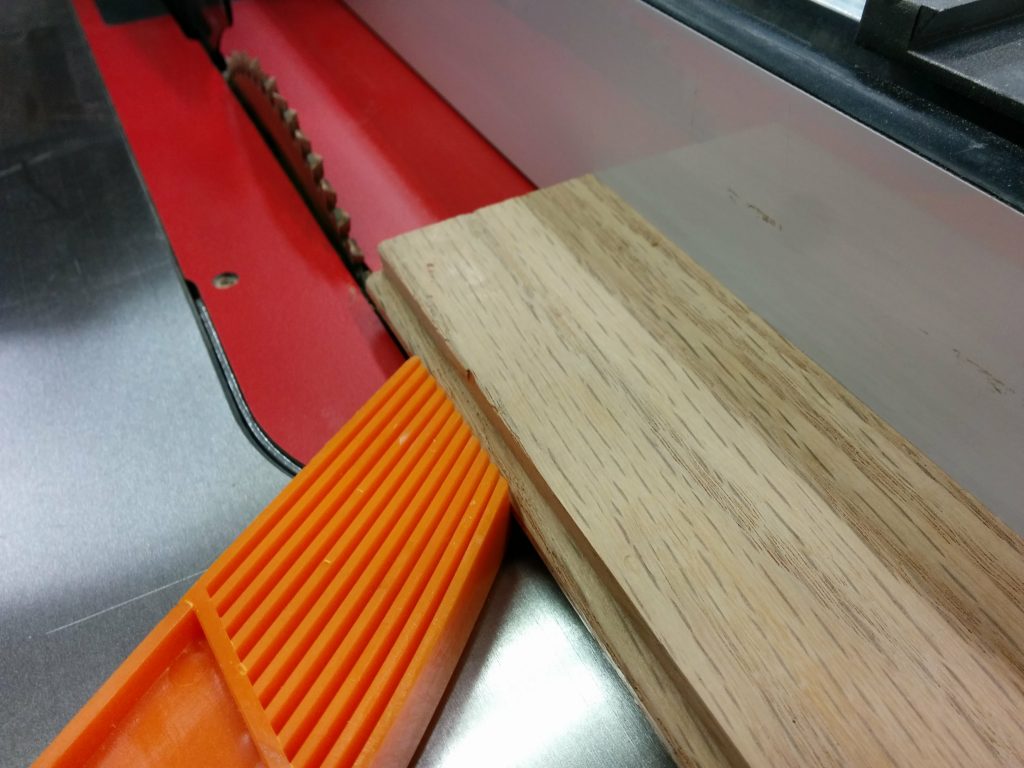
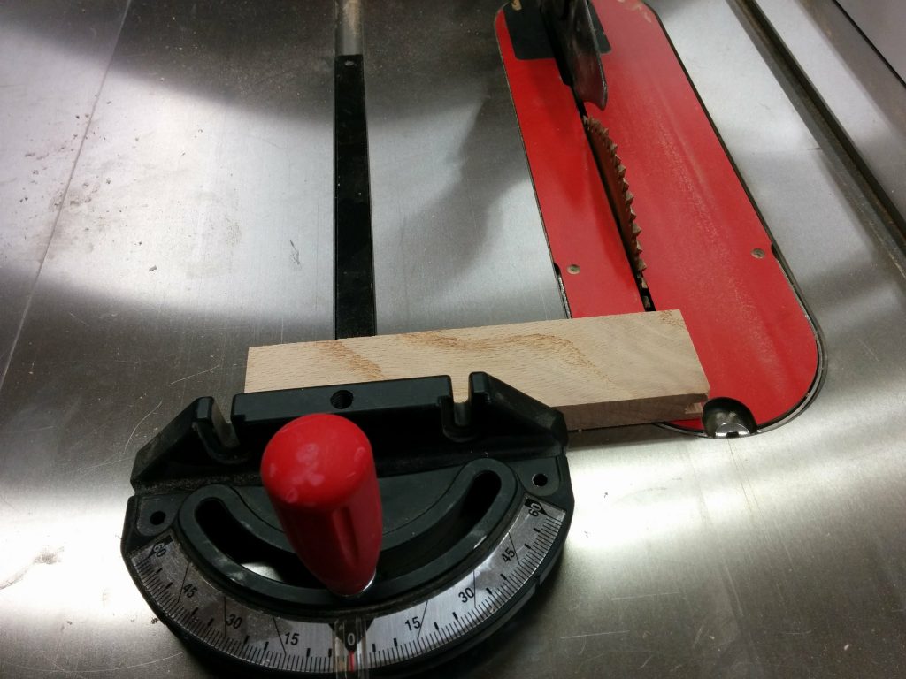
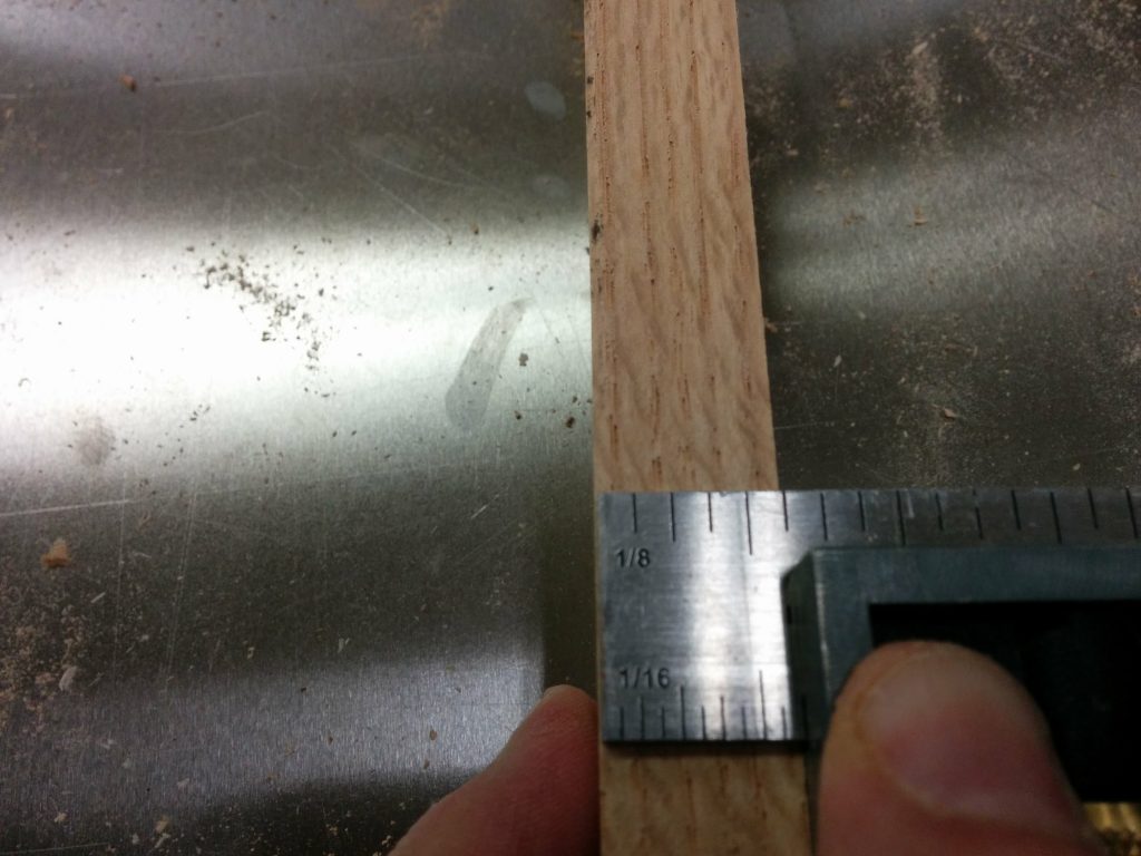
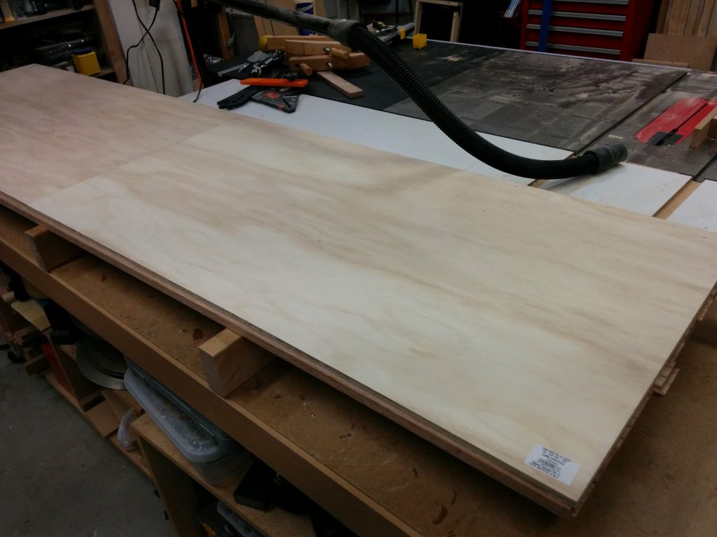
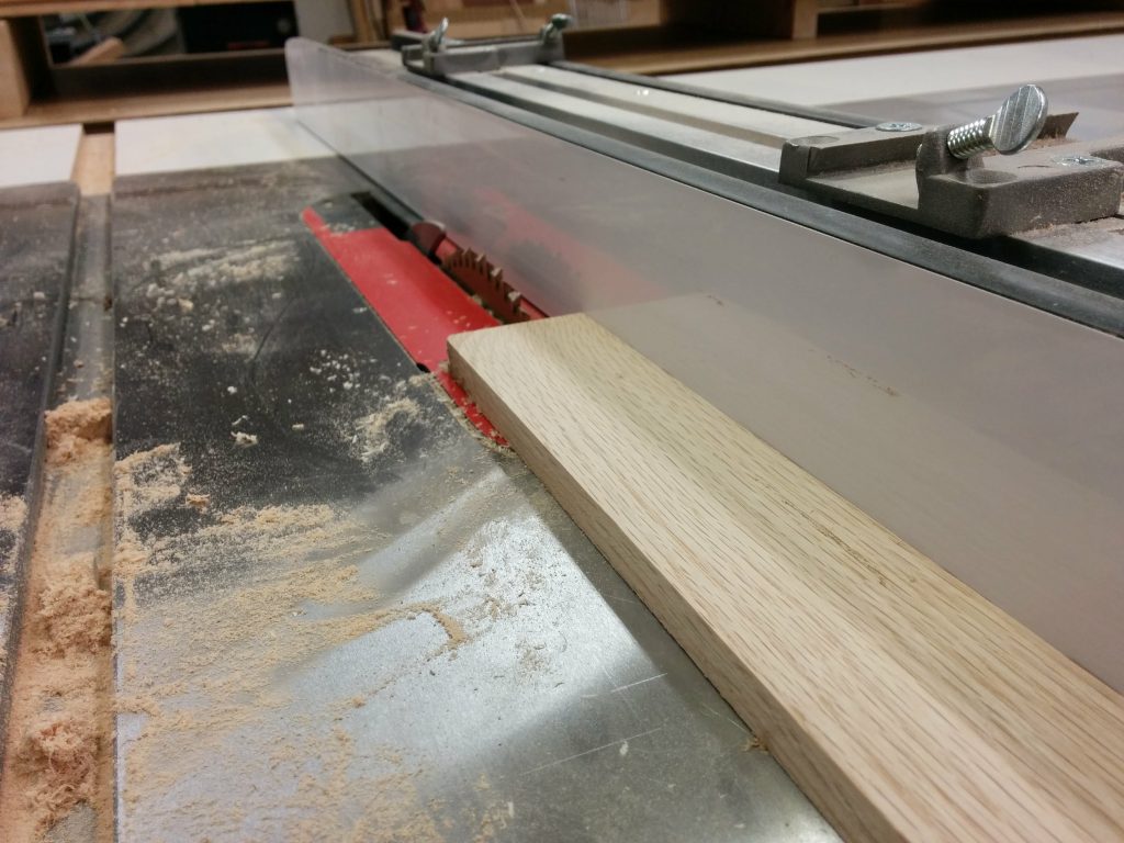
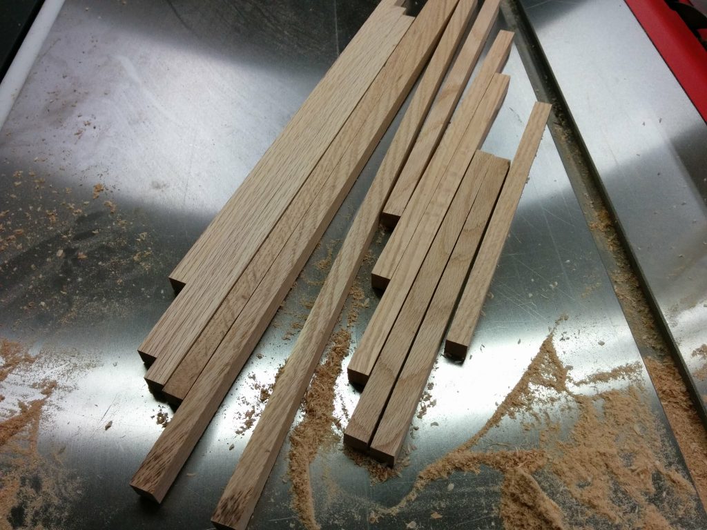
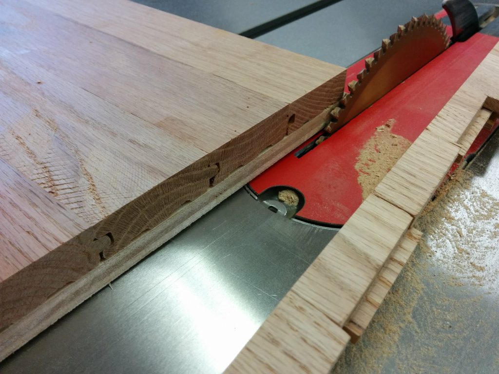
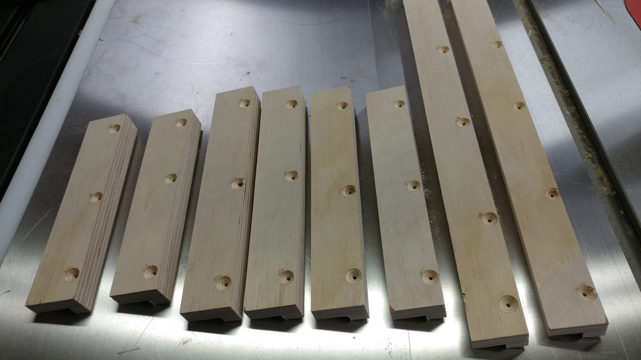
I needed to make a simple frame inside the doorways. I figured out the sizes of plywood strips that I’ll need and cut them out on my table saw.
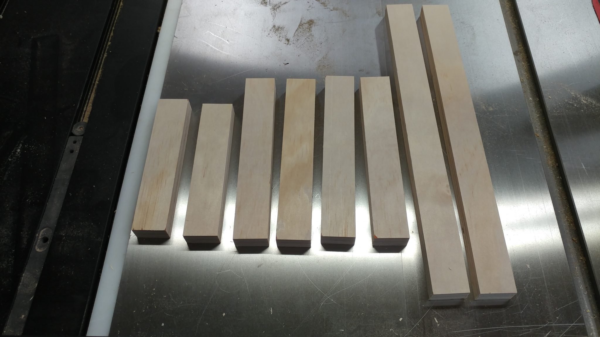
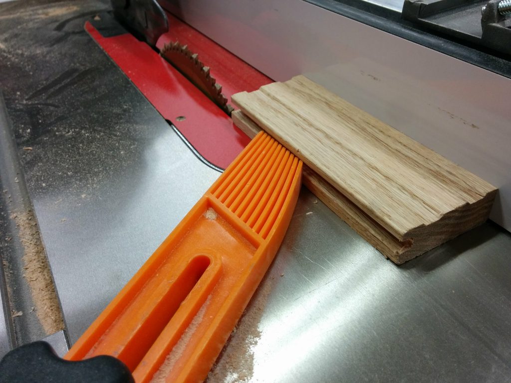
The pieces make a frame inside each door. I need to add a rabbet to each piece so the seal has somewhere to rest.
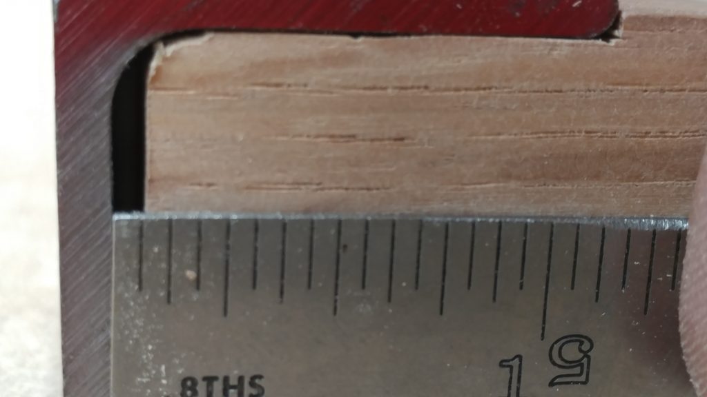
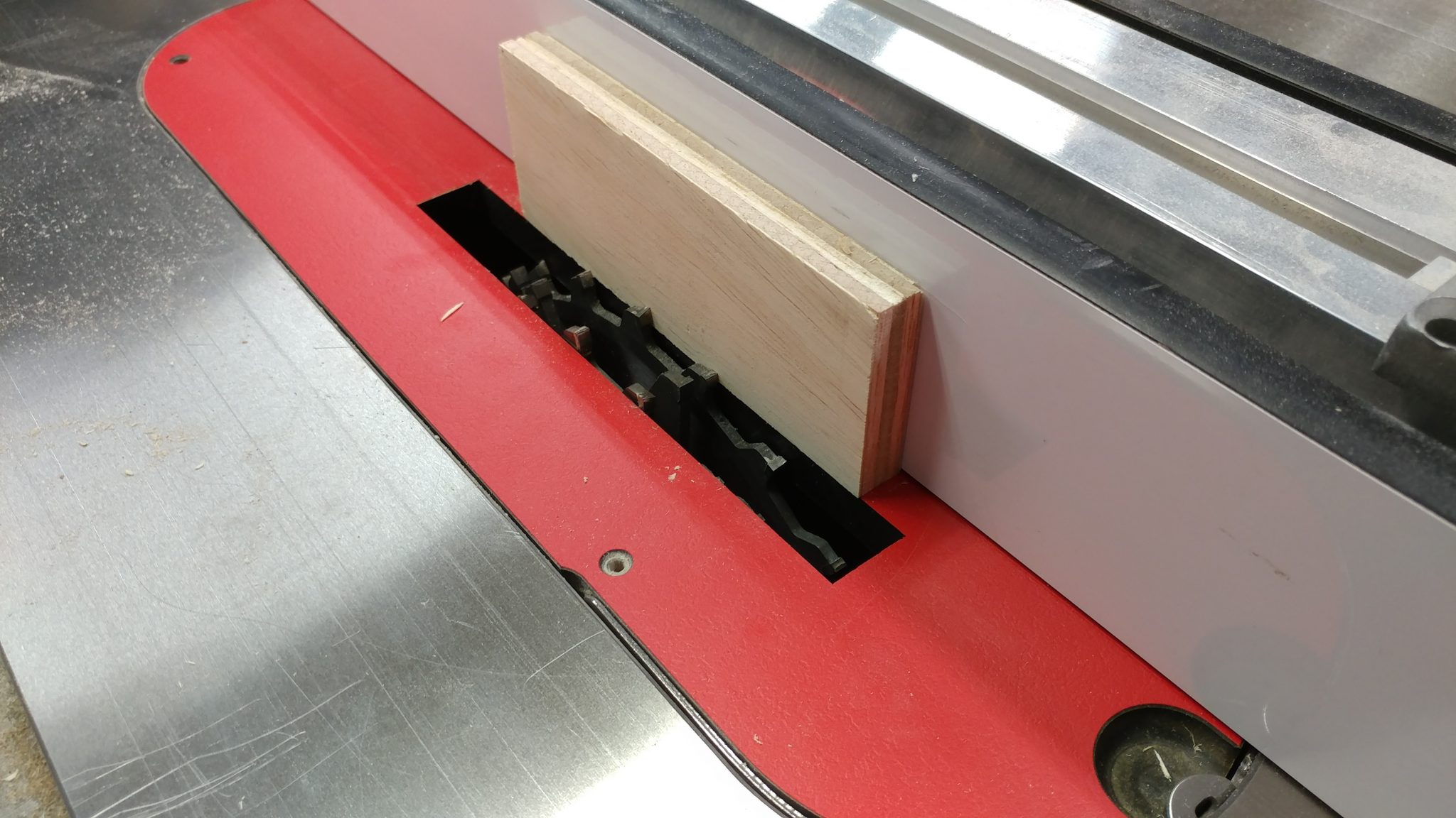
I set up my dado stack to cut just a bit shallower than the thickness of the window seal, which is 1/4″ thick.
I wanted to add a 3/4″ wide dado stack, that is 1/2″ from the edge.
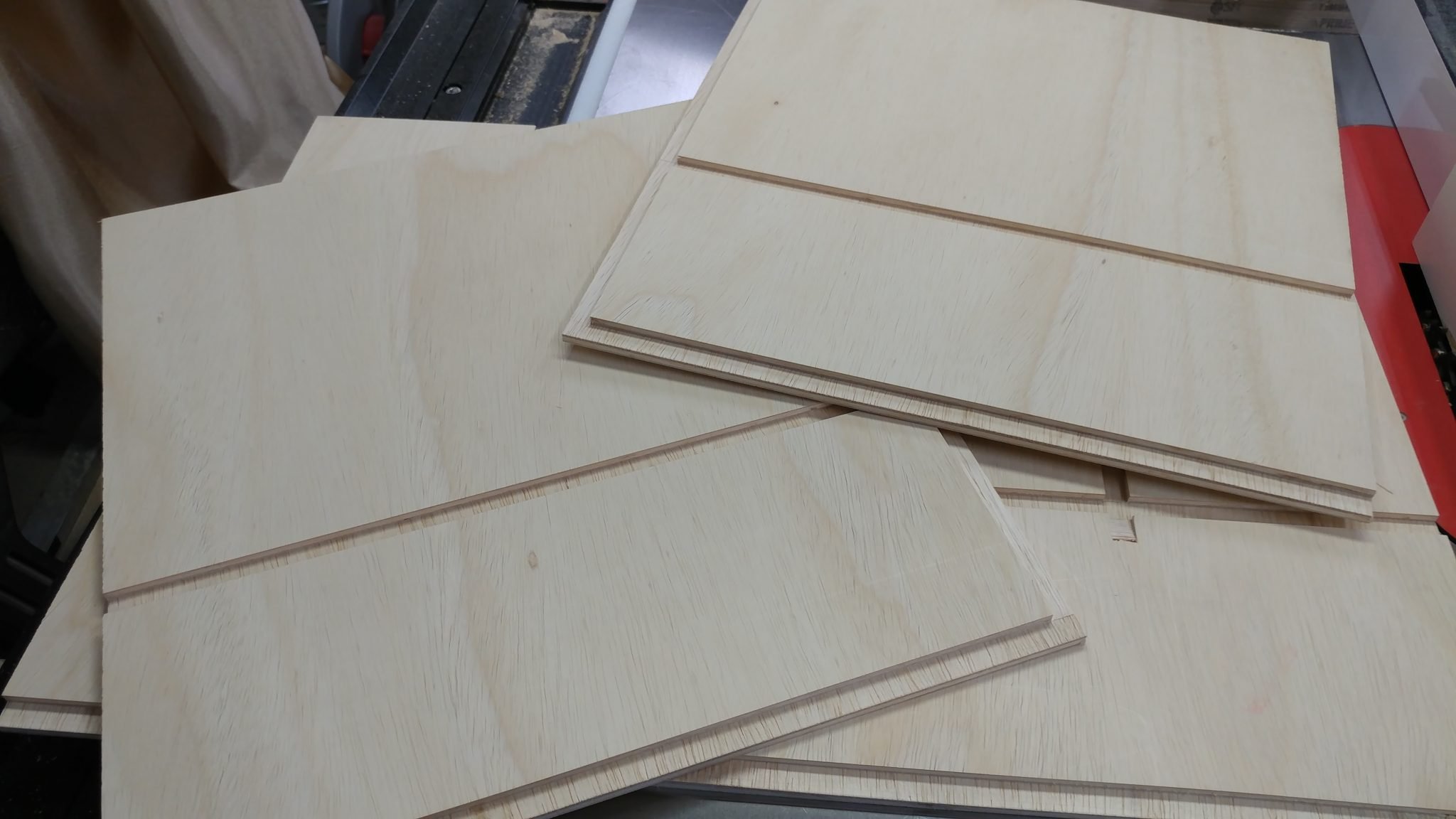
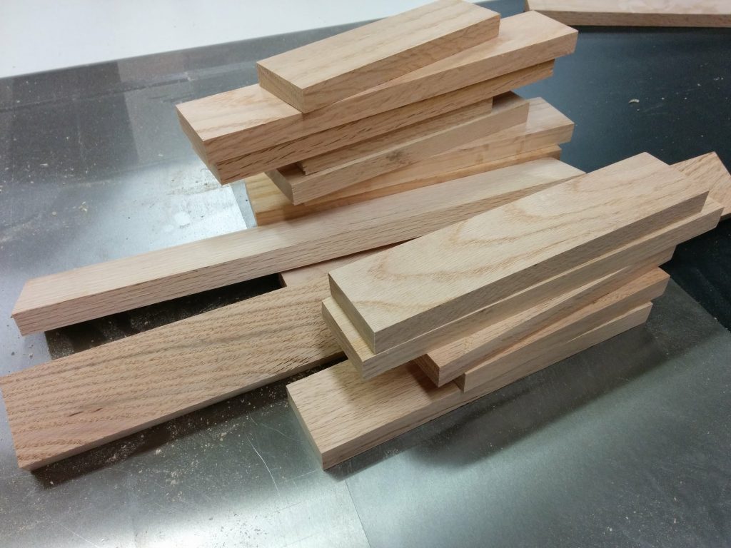
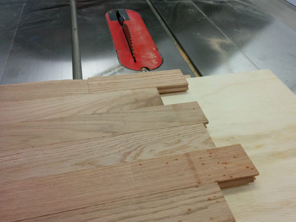
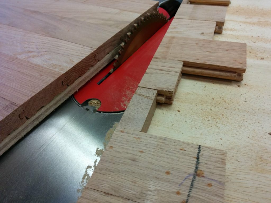
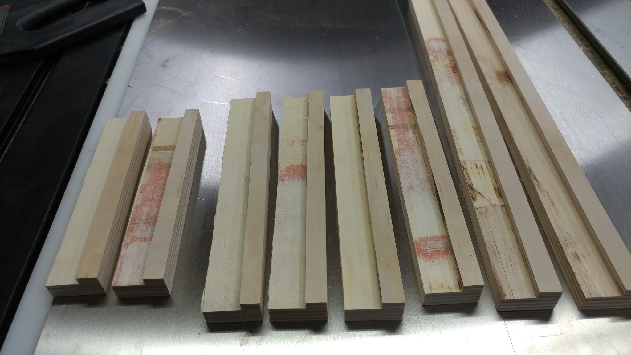
I added the rabbets to each piece…
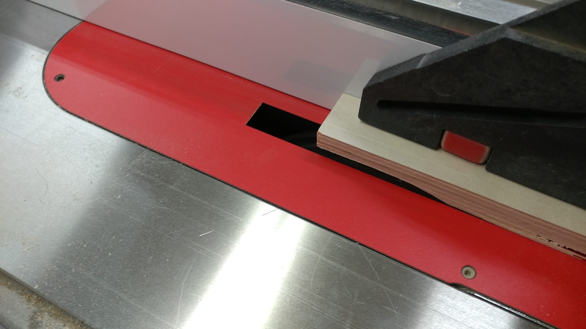
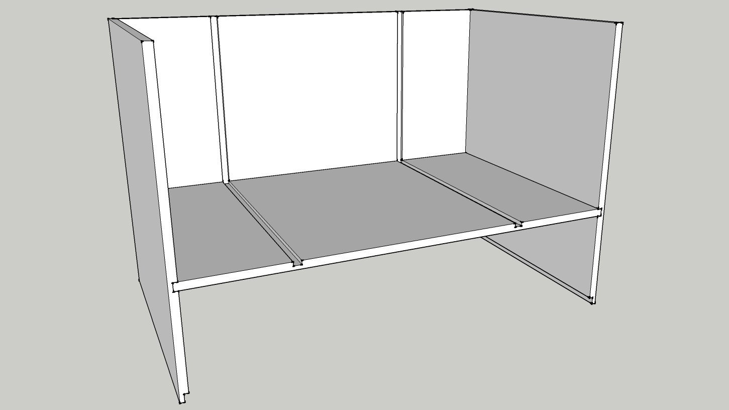
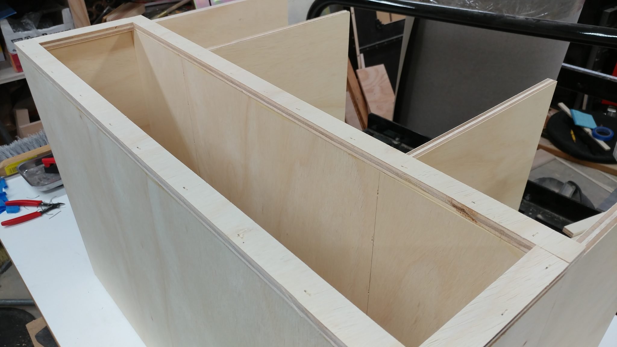
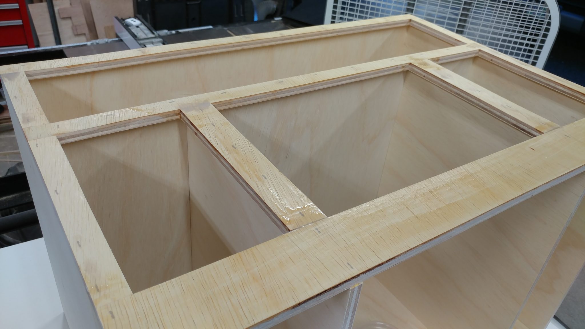
…making the frame pieces.
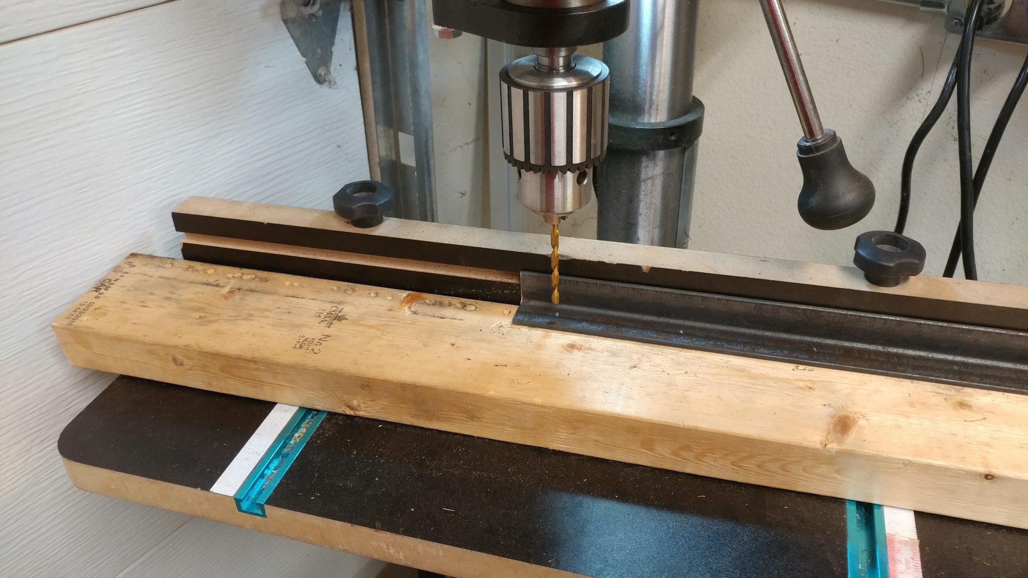
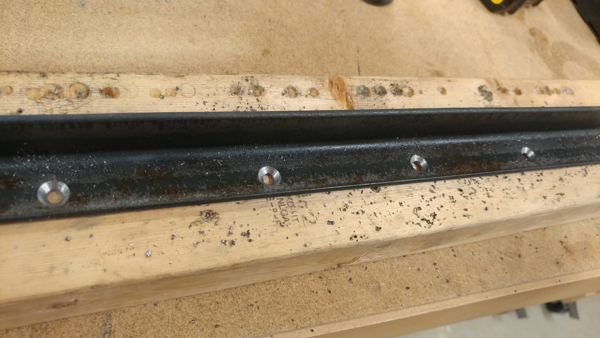
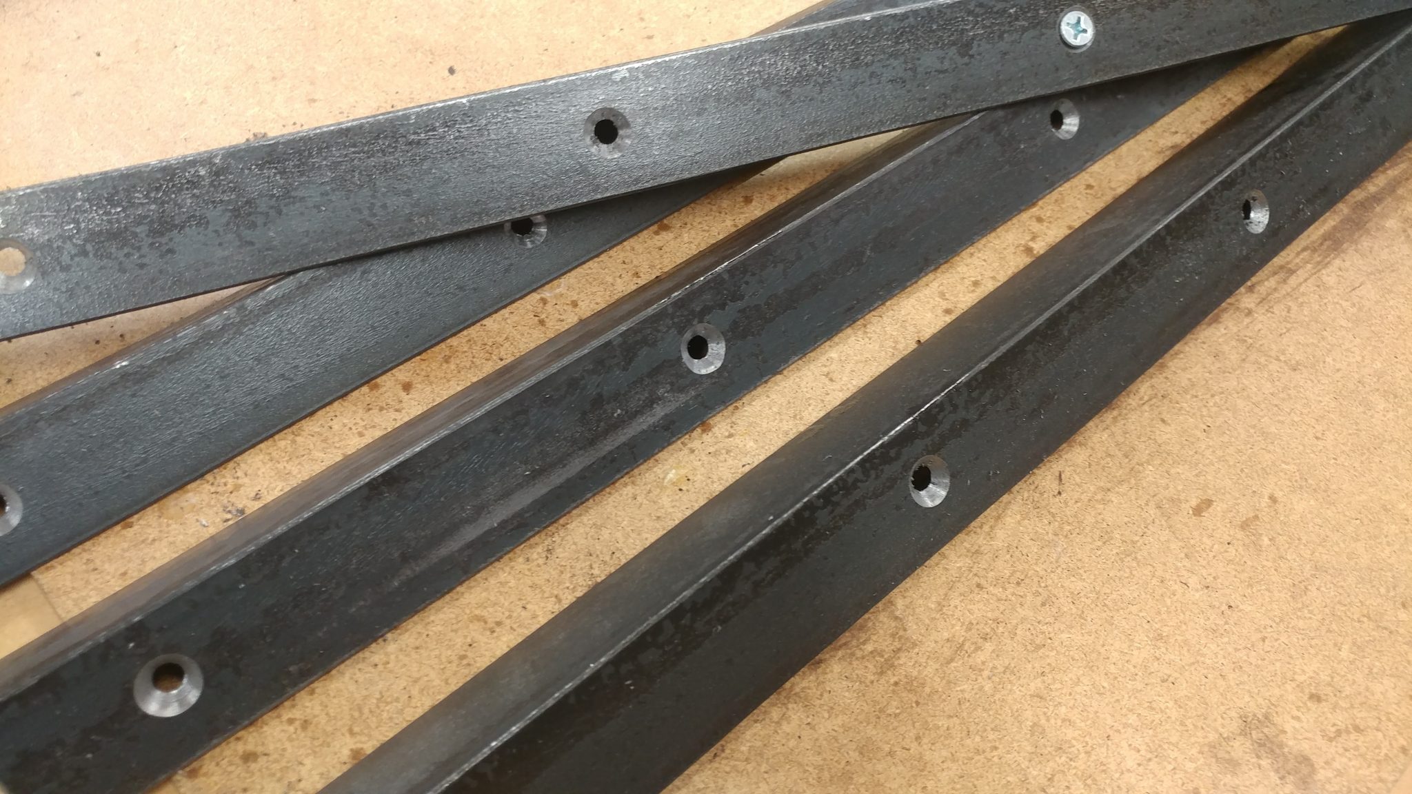
I pre-drilled and counter-sunk holes through the thickest parts of the frame pieces.
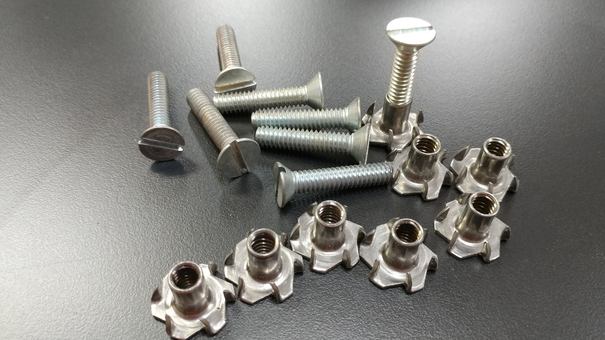
I inserted screws into each piece to make it easier to attach.
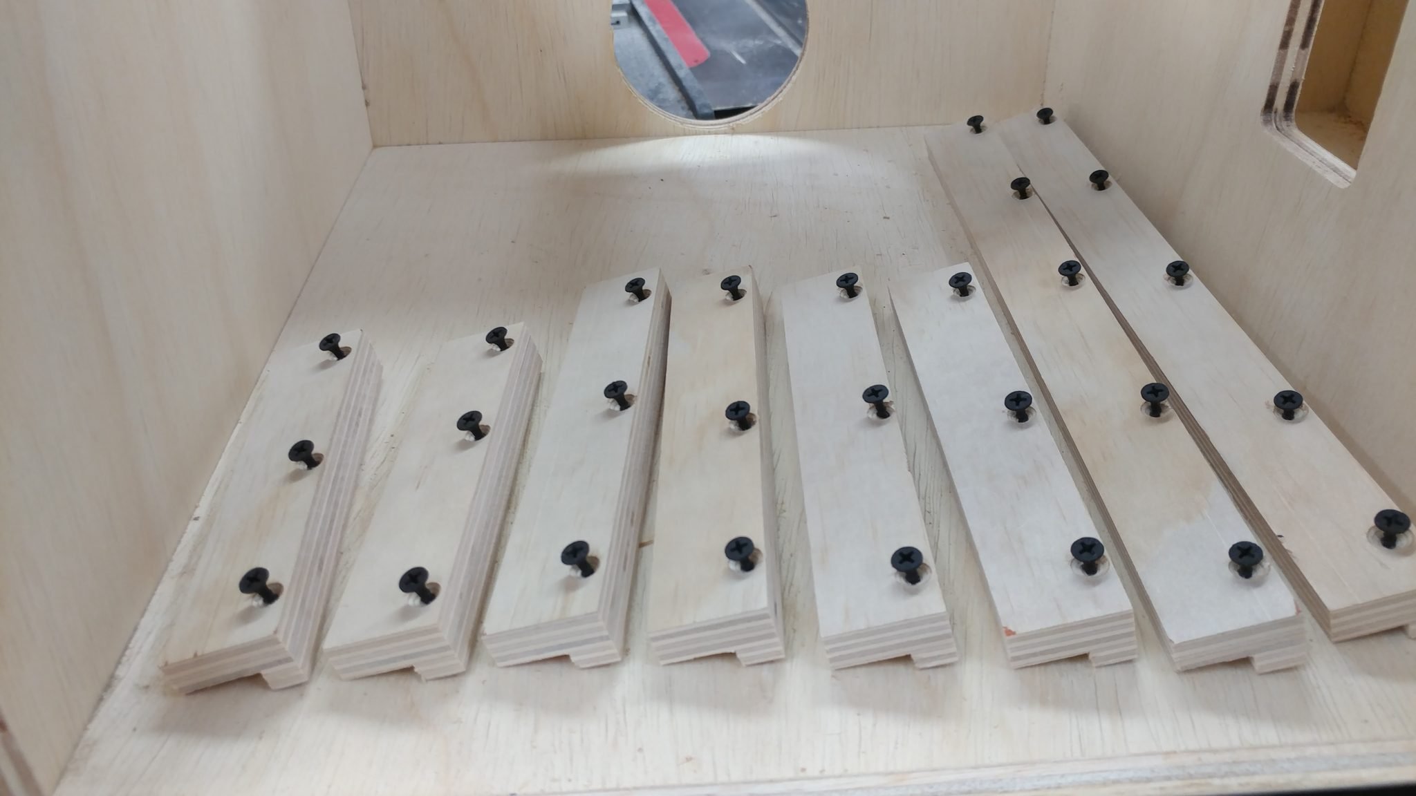
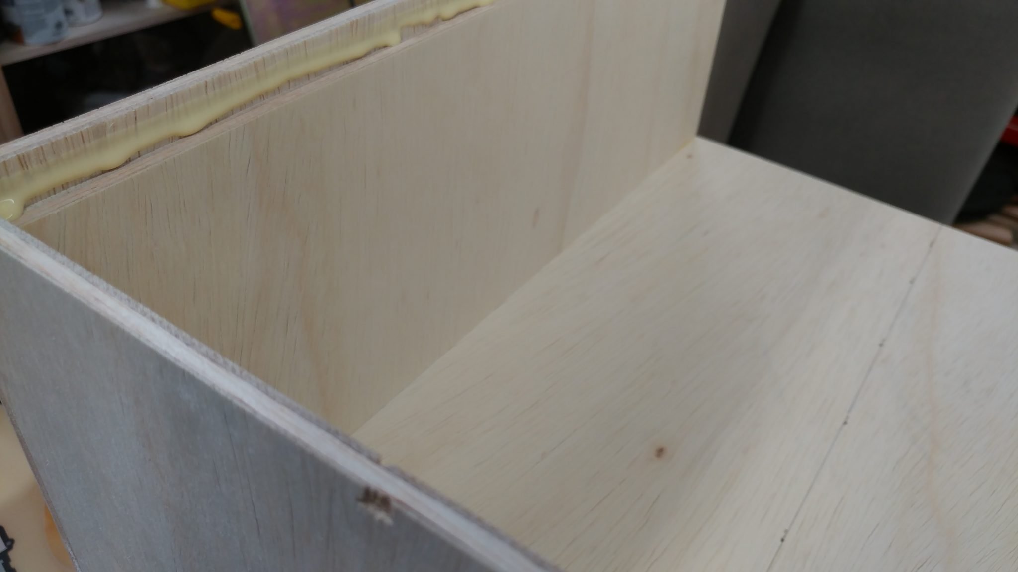
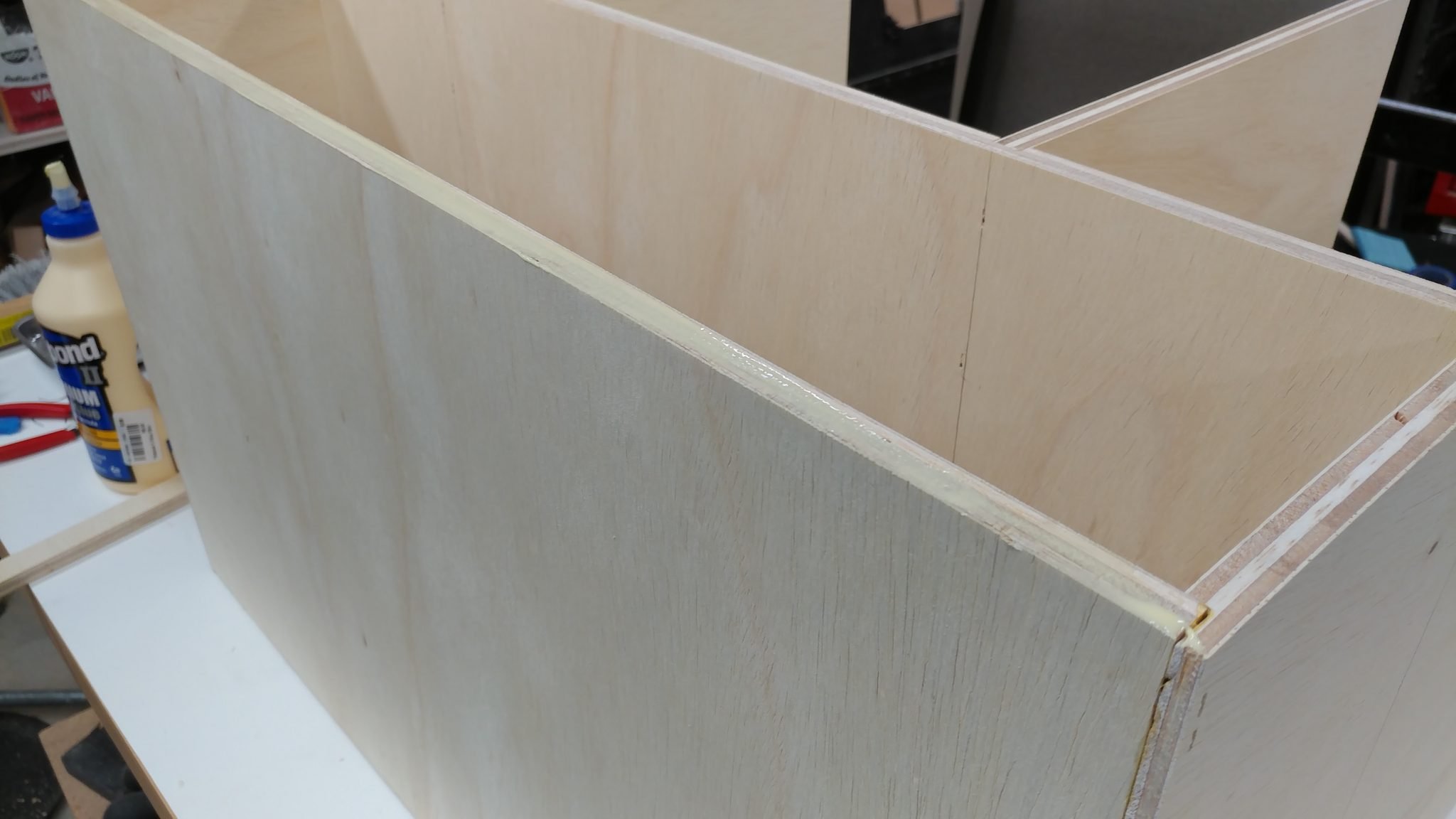
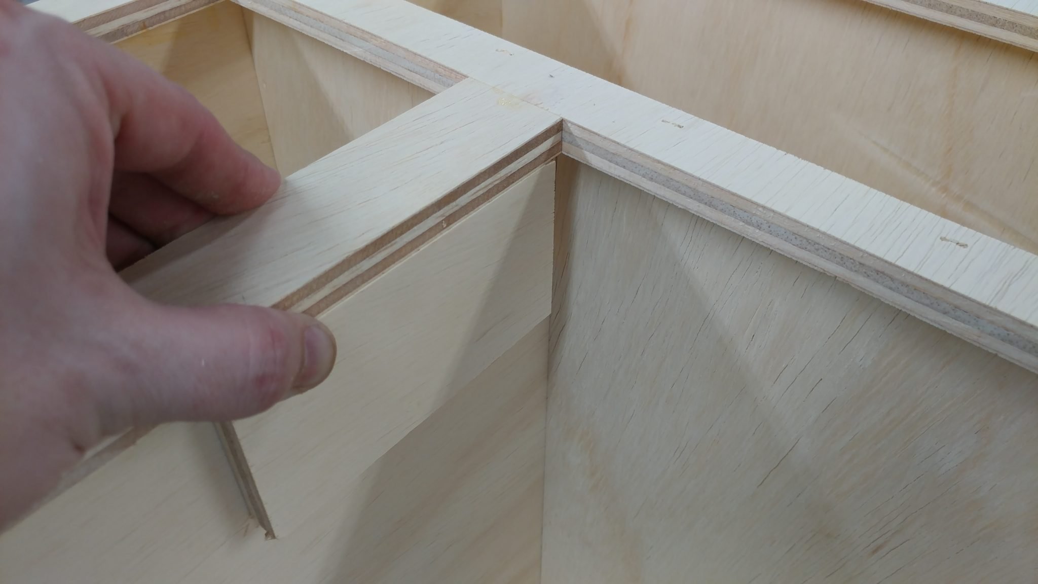
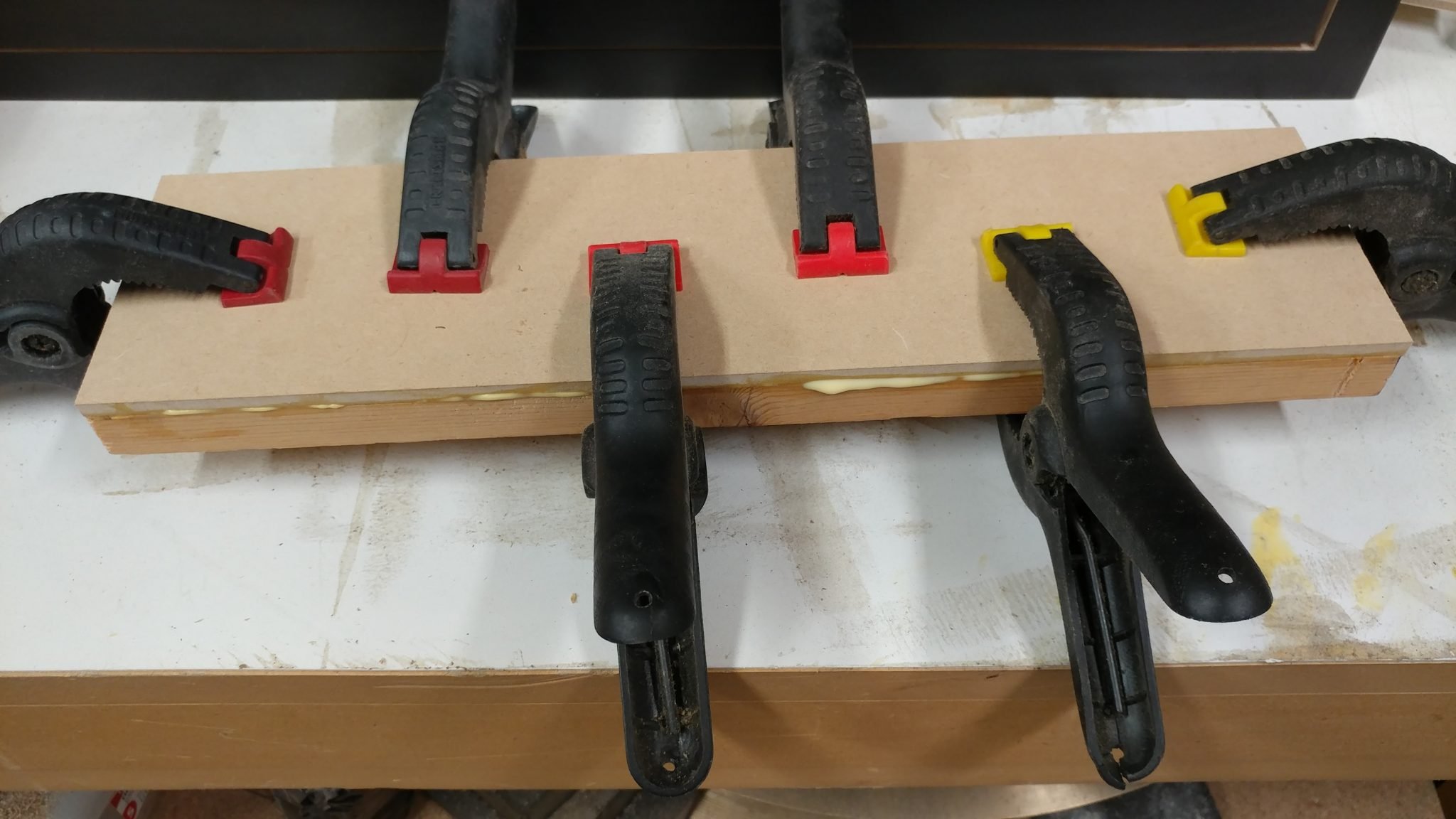
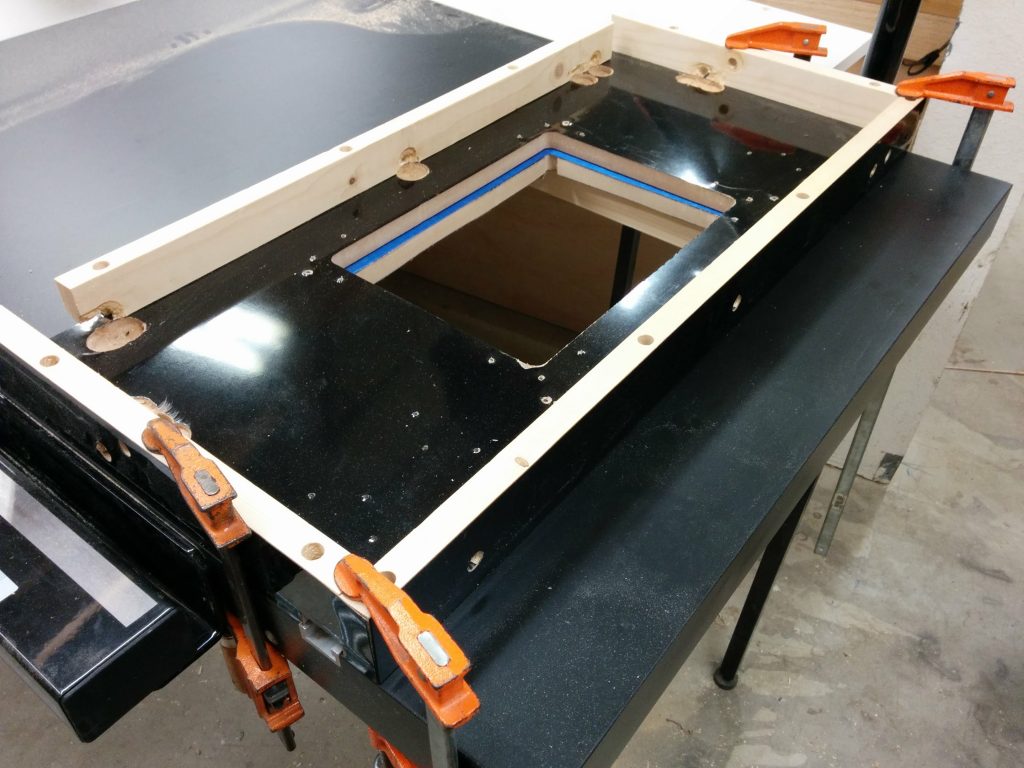
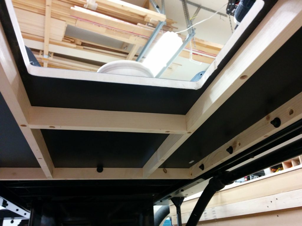
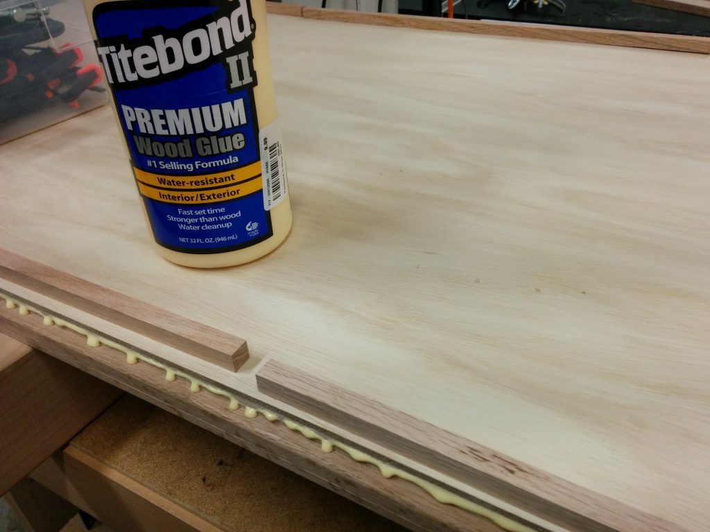
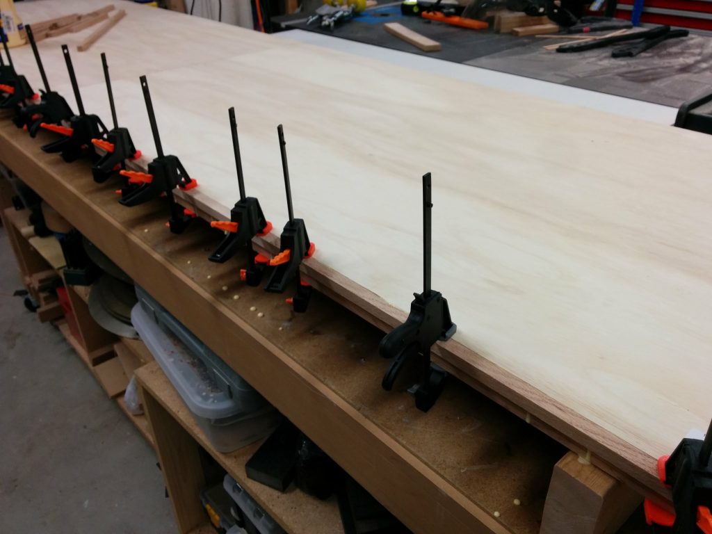
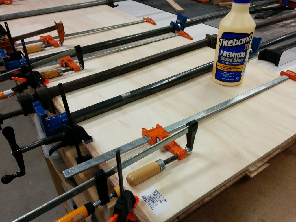
I glued and screwed each frame piece in place.
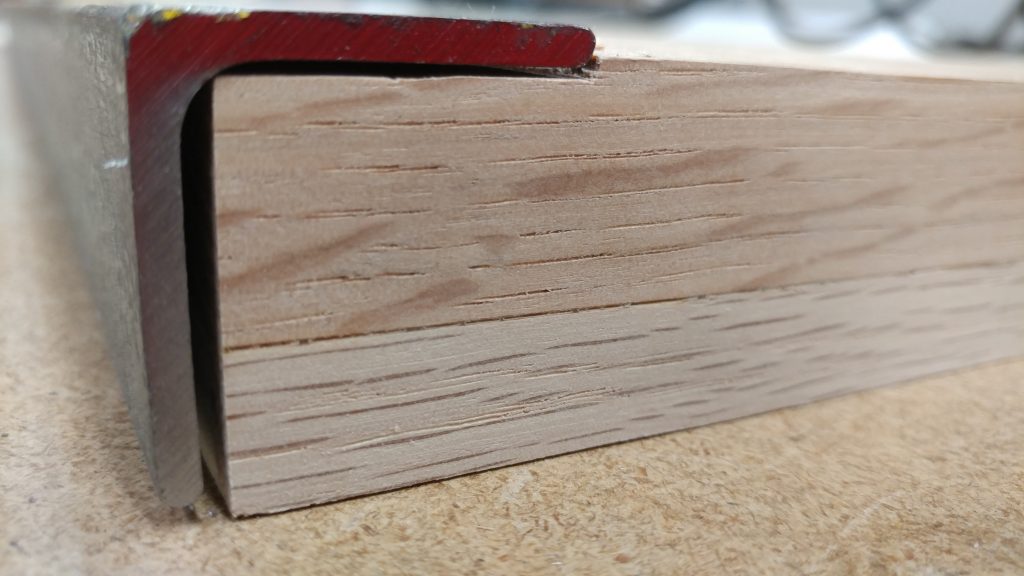
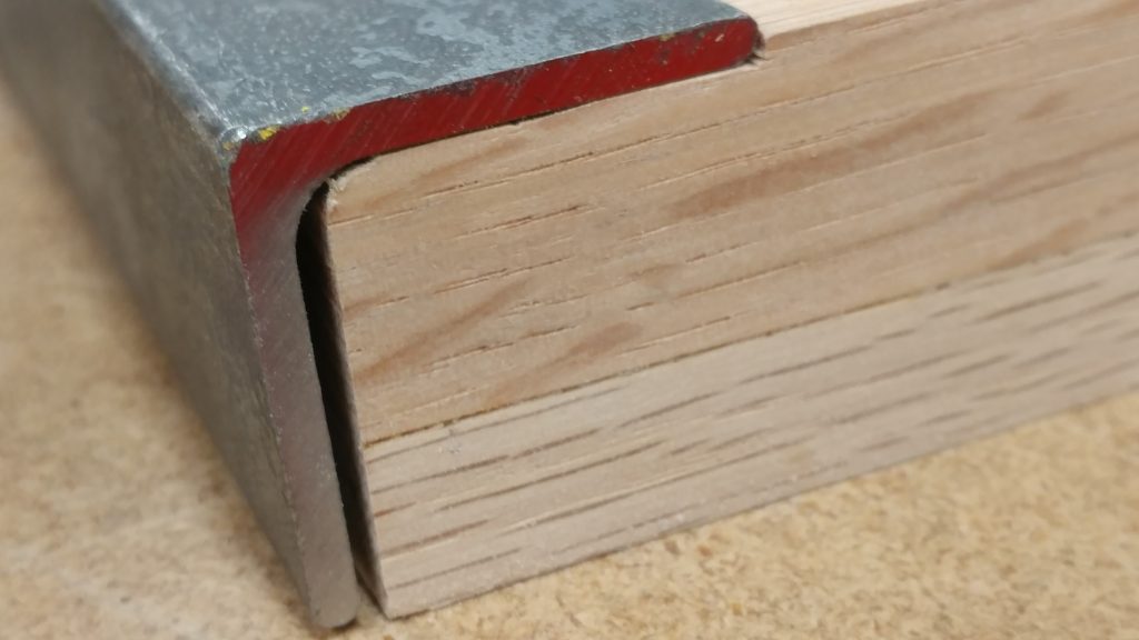
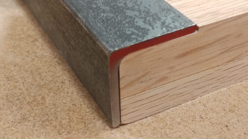
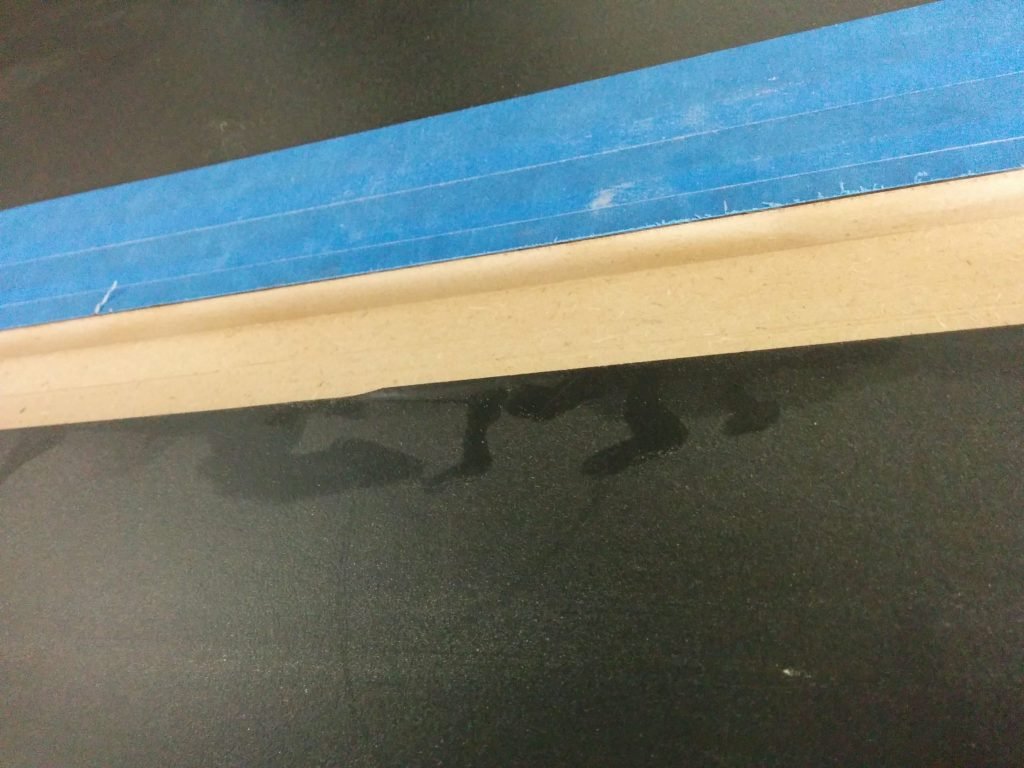
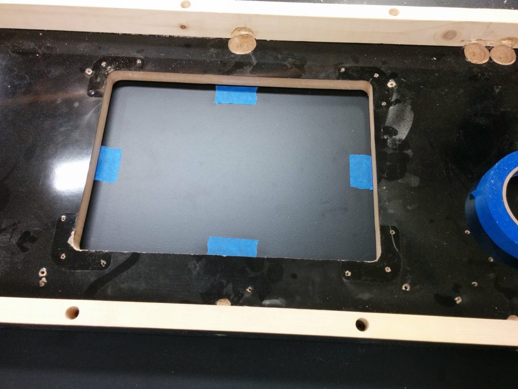
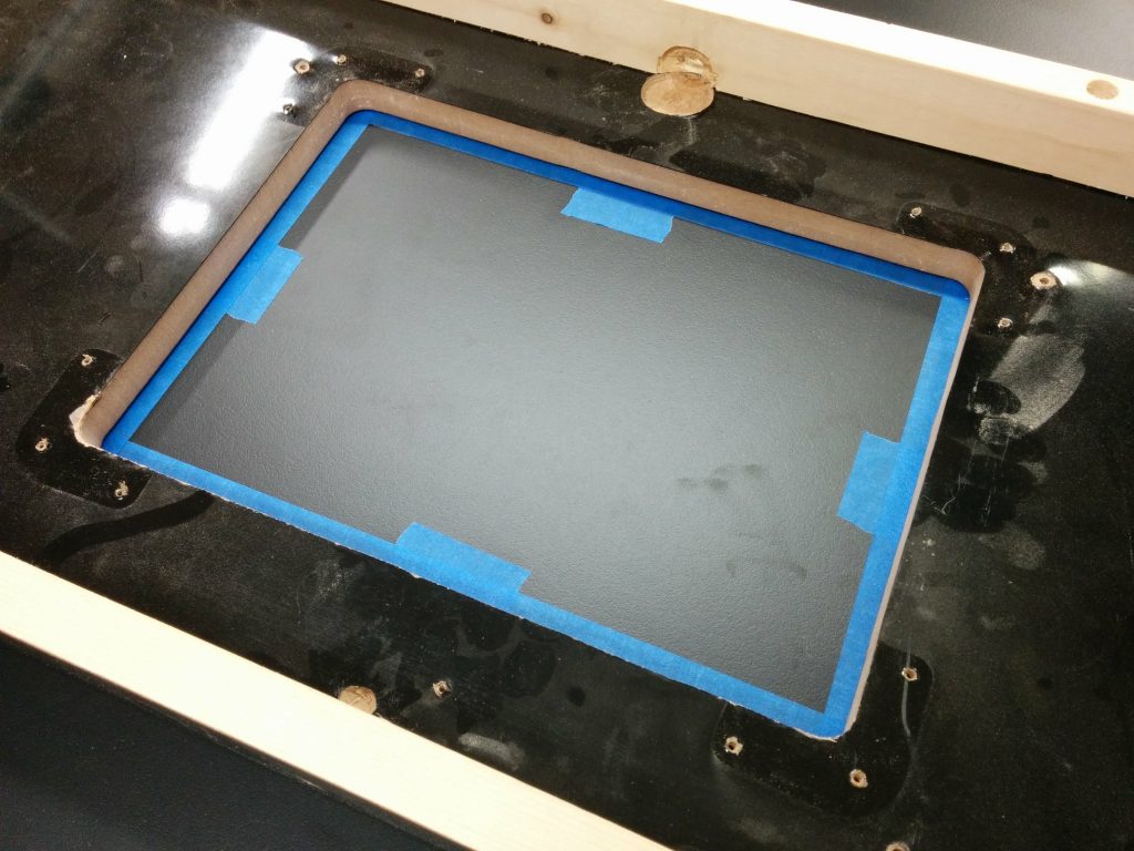
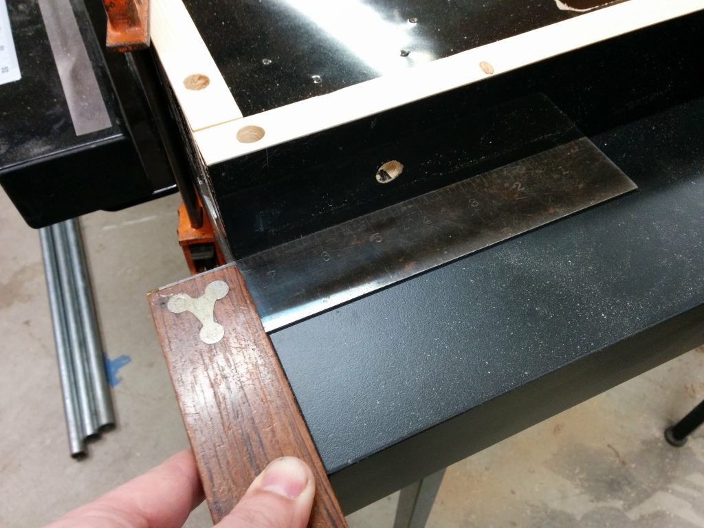
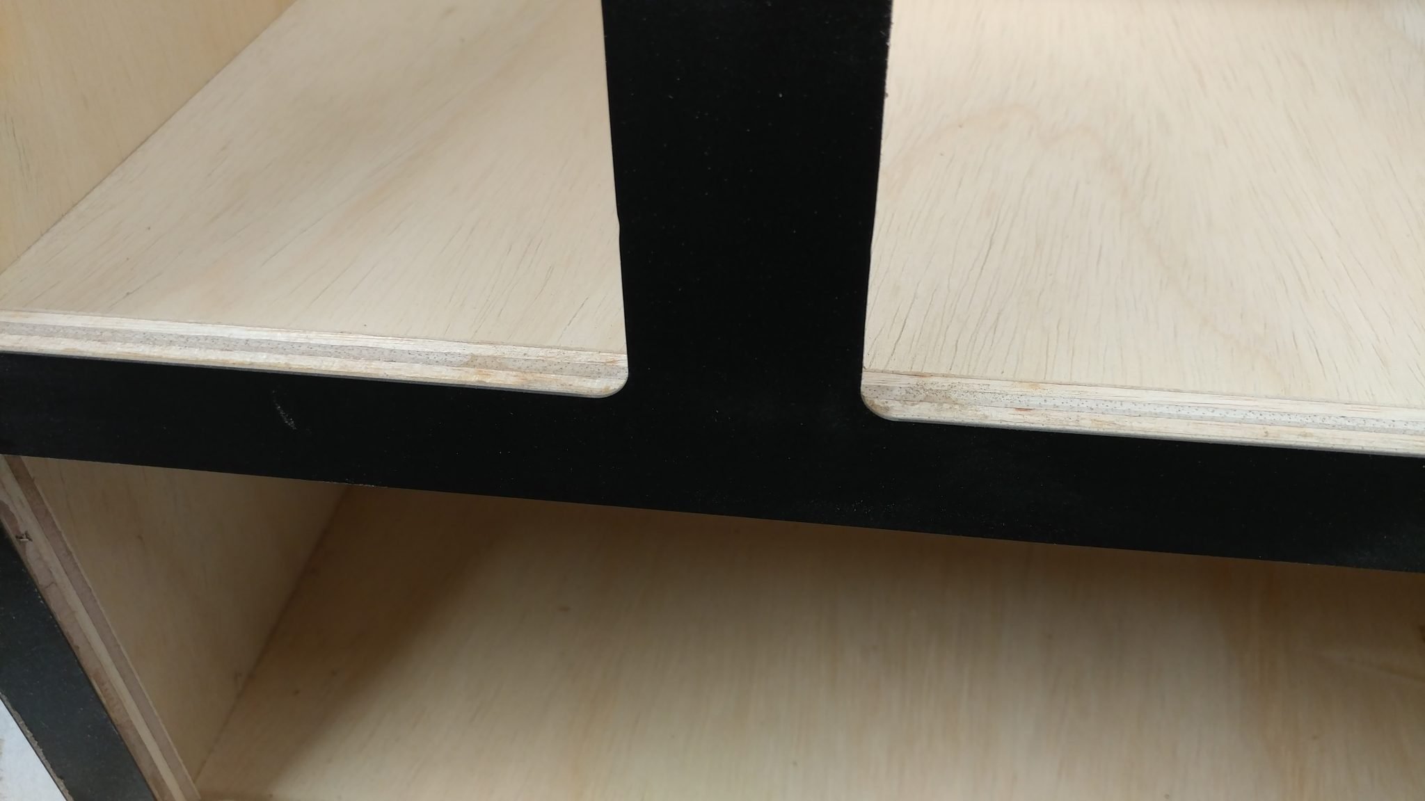
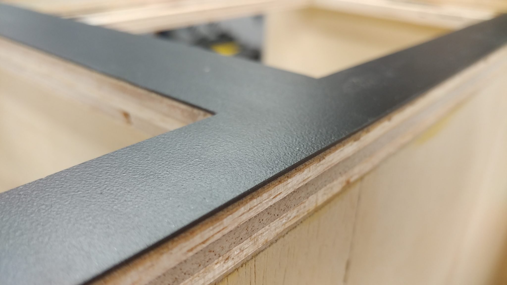
Before attaching the window seal, I want to clean up the edge of the laminate. I do this with a 7-degree bevel bit. I have the bit just barely protruding from the base of the router and run this along each edge.
It has trouble getting into the corners but it cleans up the rest of the edges really nicely.
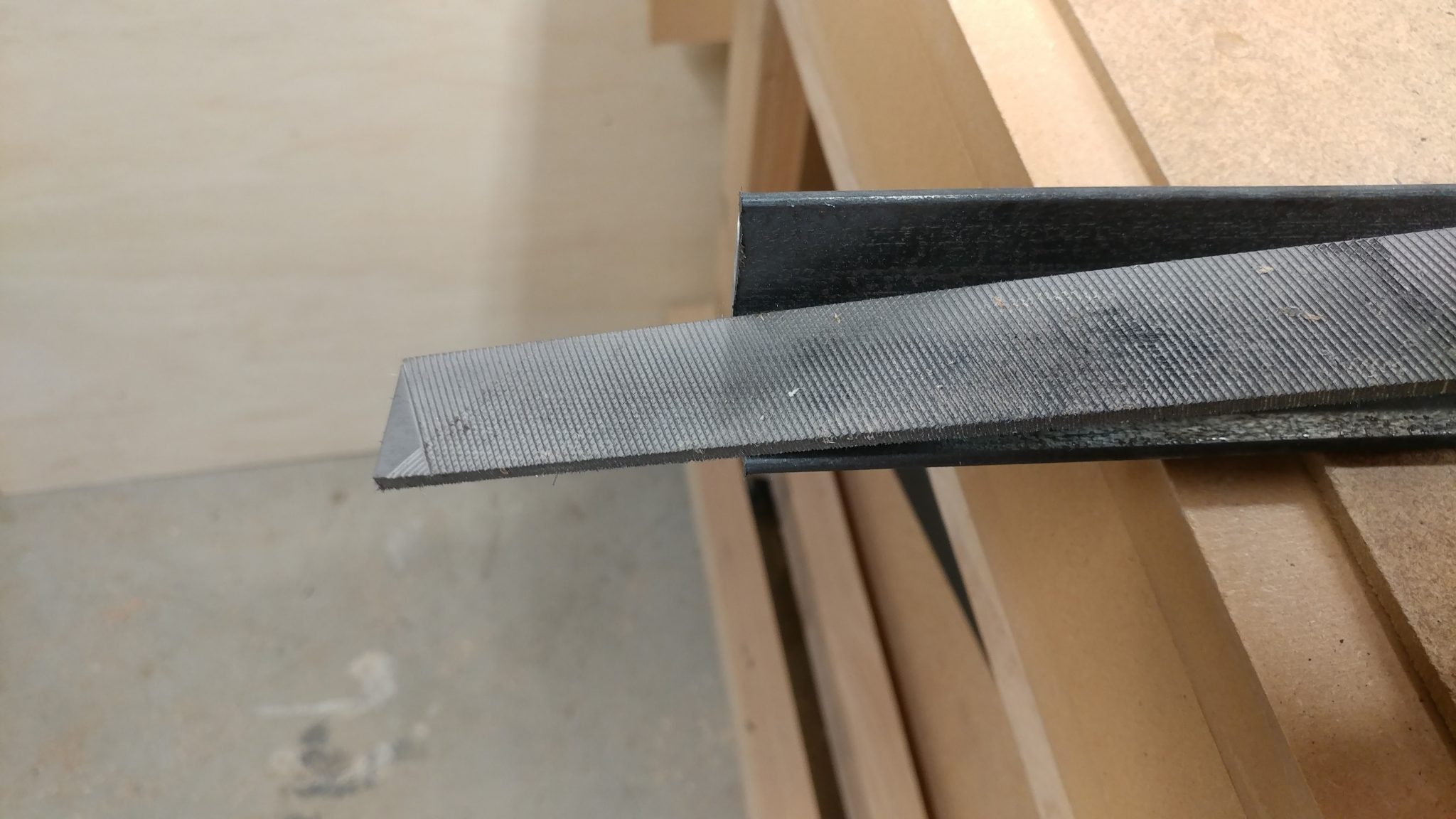
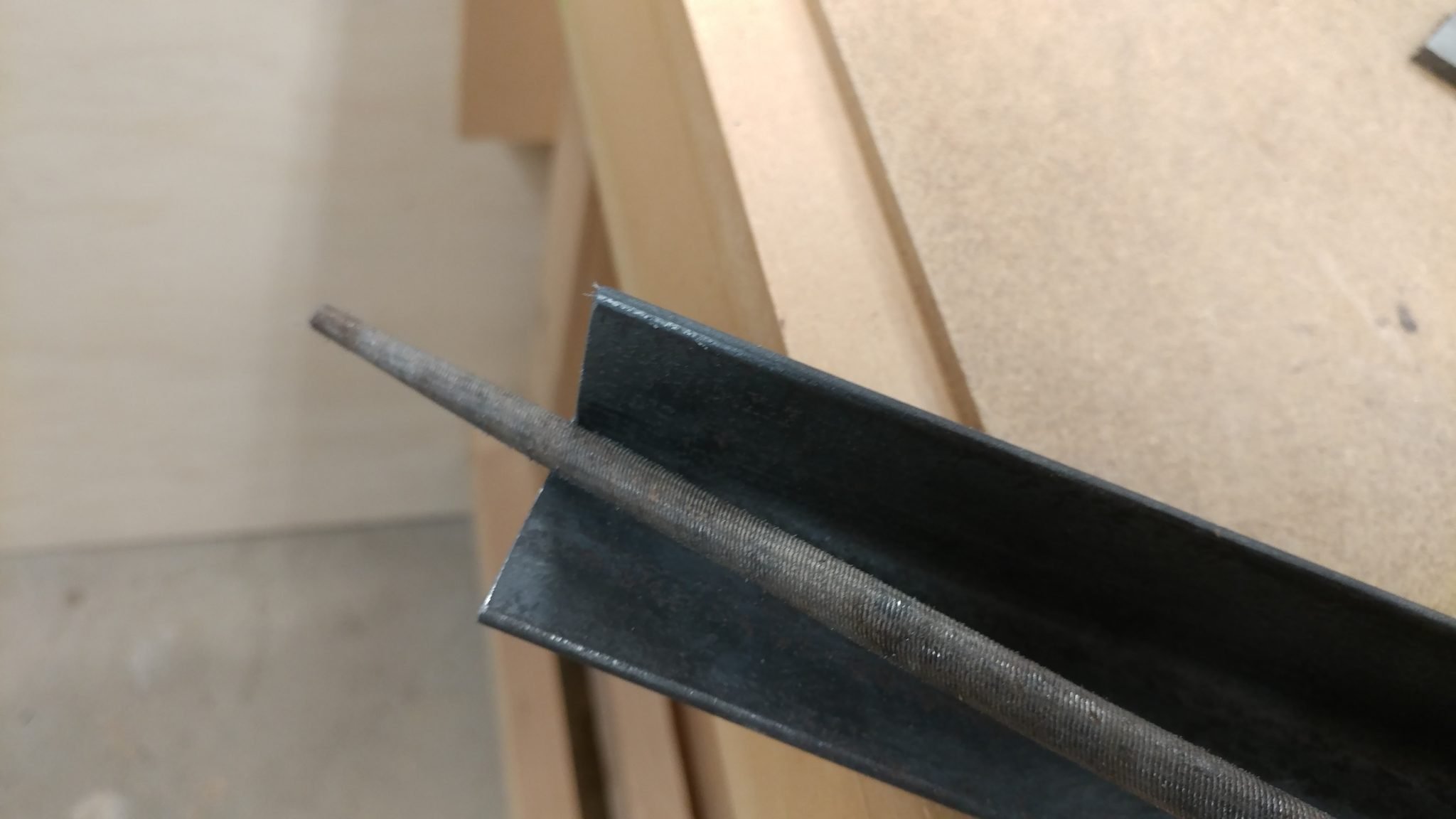
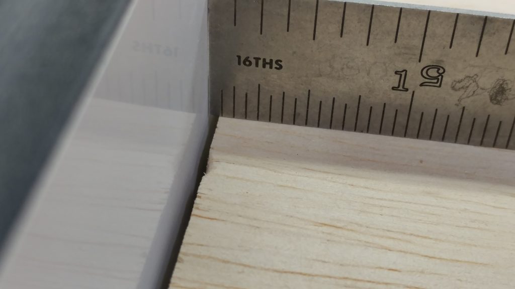
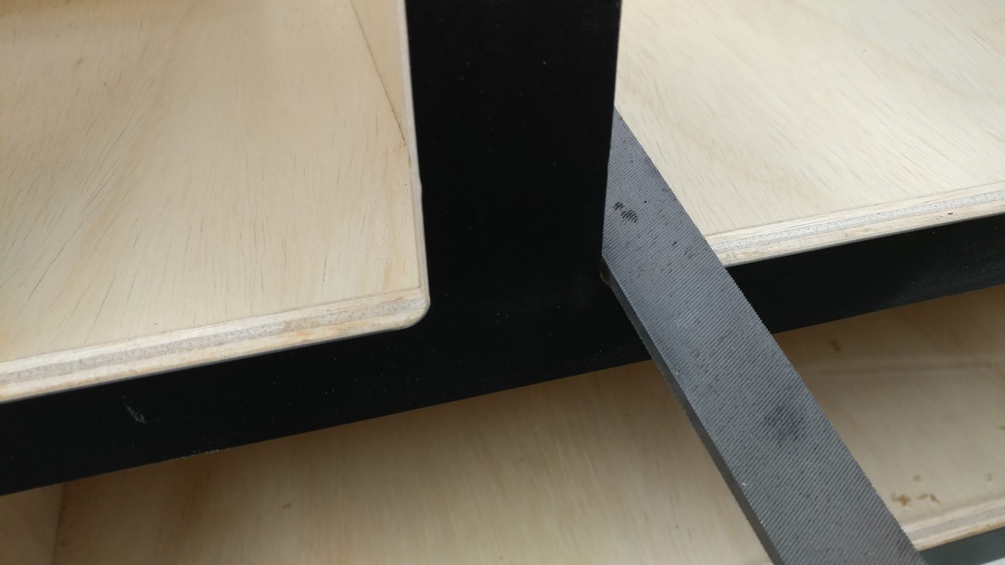
I then do a pass at about 45-degrees with a hand file. This is also how I clean up the corners.
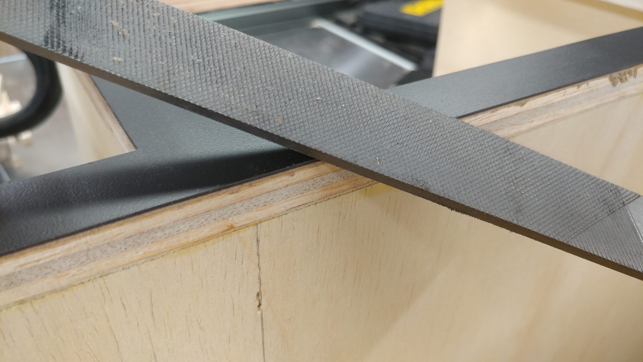
The end result is a nice edge that isn’t too sharp and will help prevent chipping.
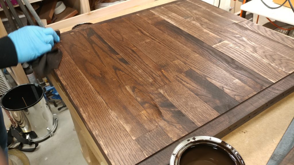
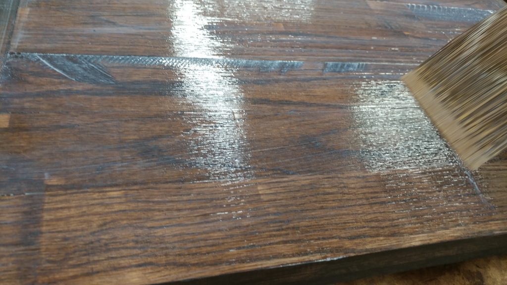
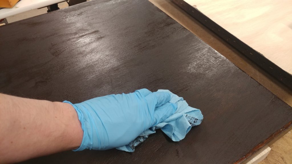
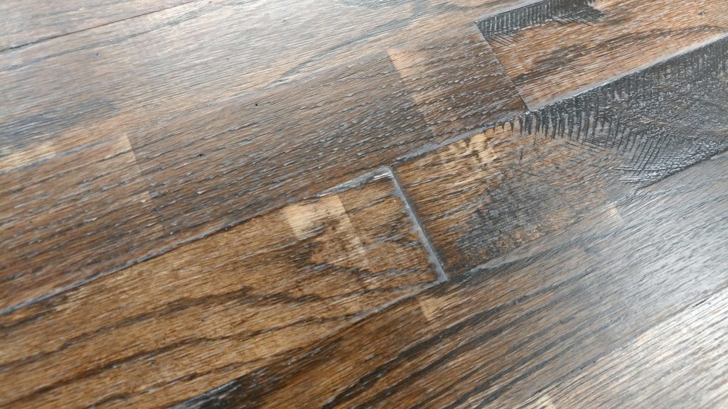
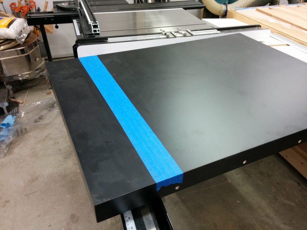
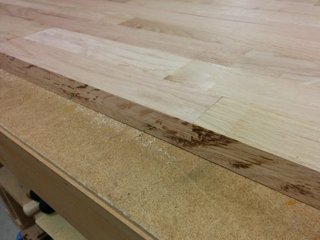
I now need to finally clean off the contact adhesive. This is really easy to do with lacquer thinner and some blue shop towels. Here is a before…
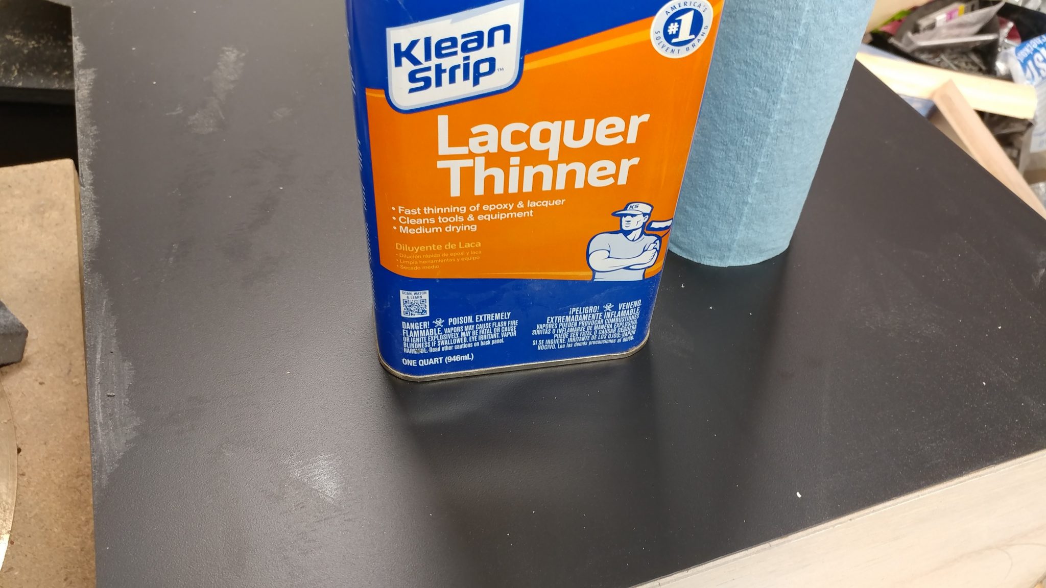
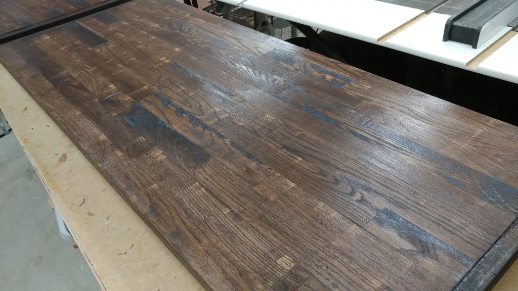
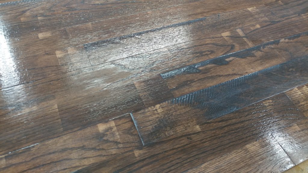
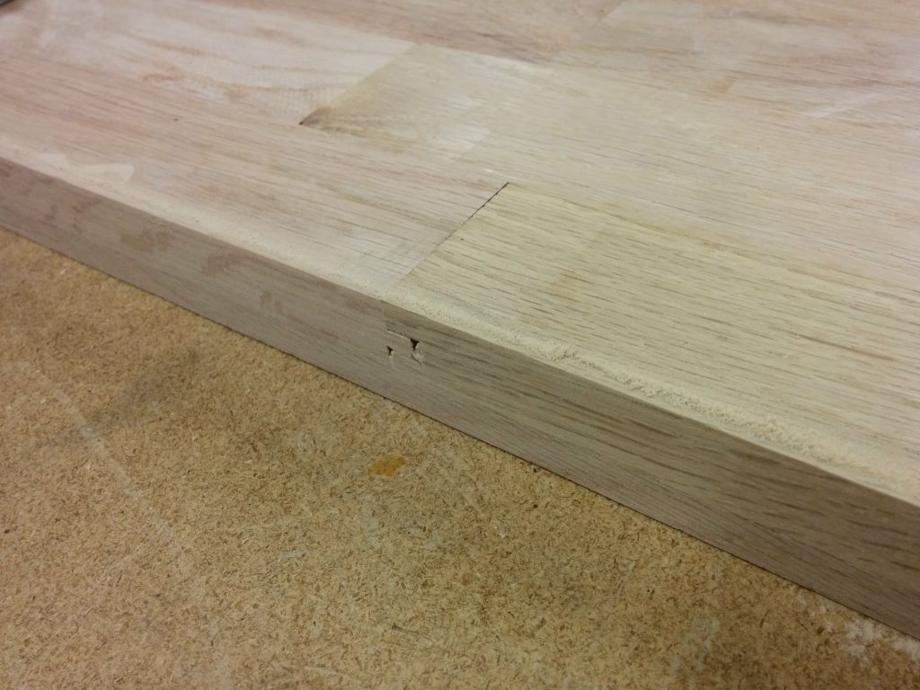
…and after.
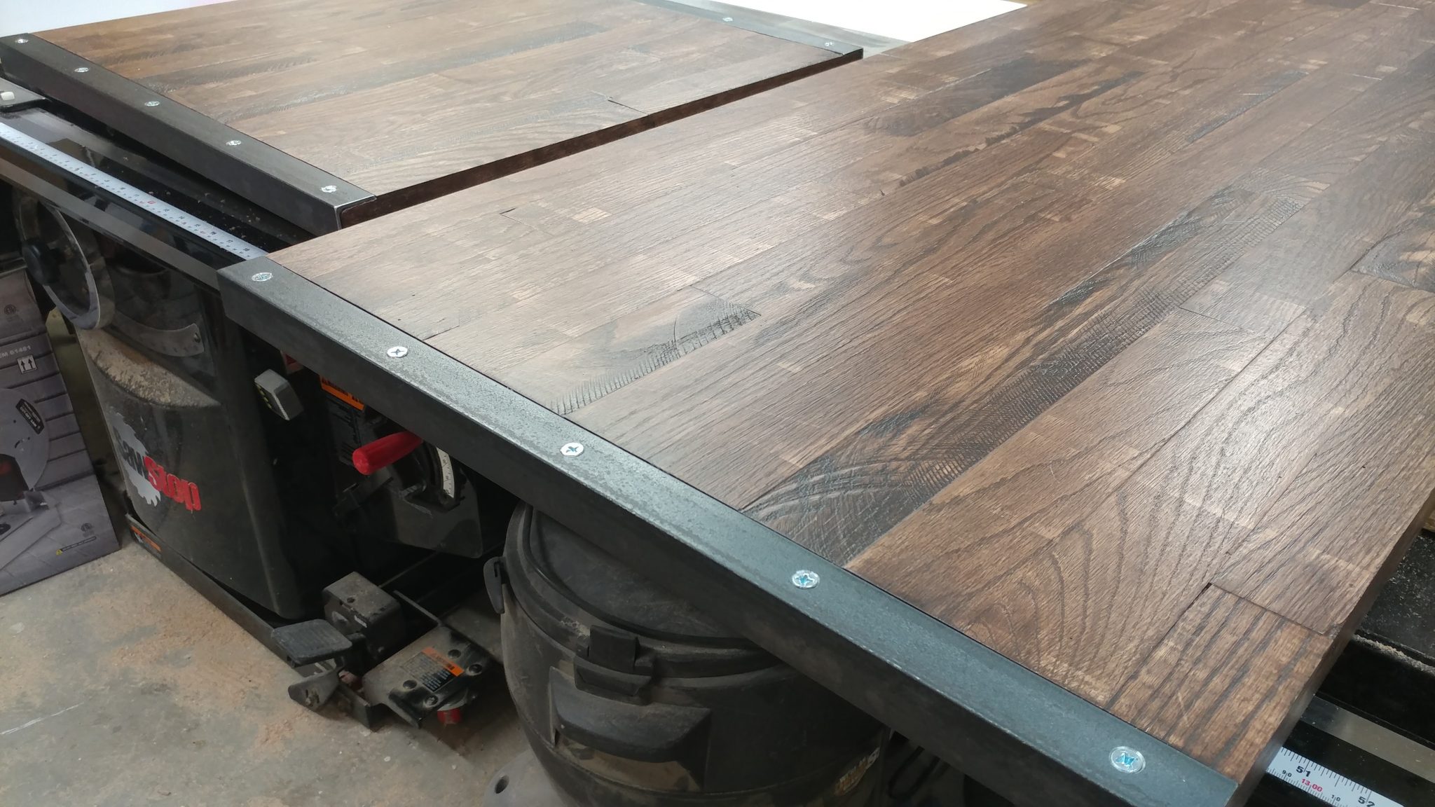
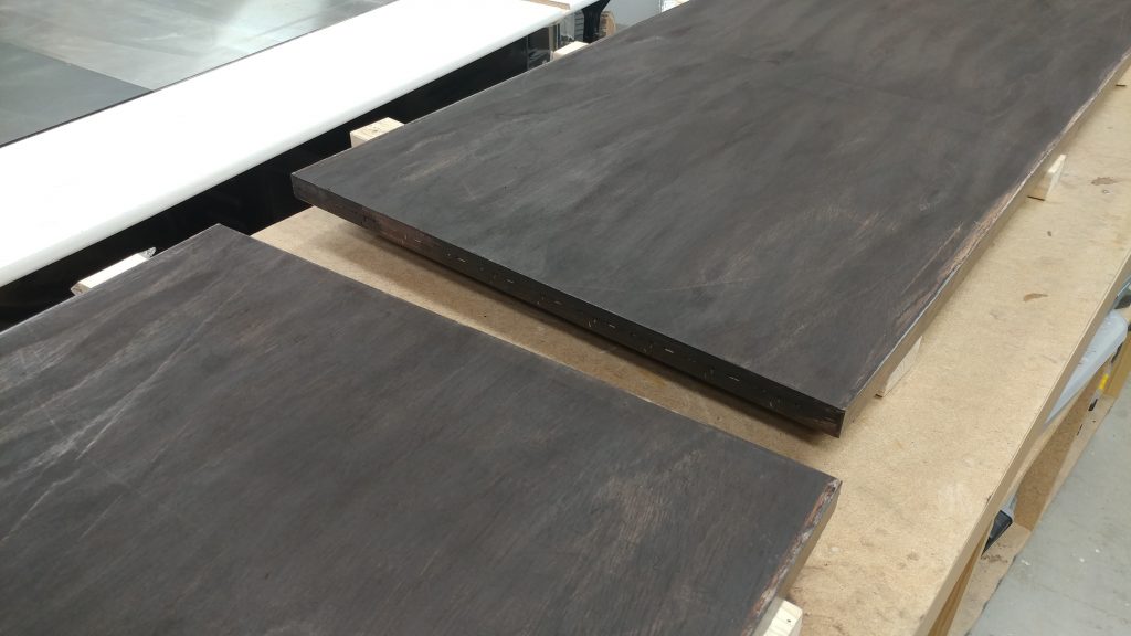
The laminate’s in place. In the next article, I’ll cover cleaning up the edges a bit more, attaching the hardware, and doing the electrical.
If you have any questions or suggestions, please leave a comment below.
<< Back to Table Saw Modification – Router Table Enclosure: Part 1 – Carcase.