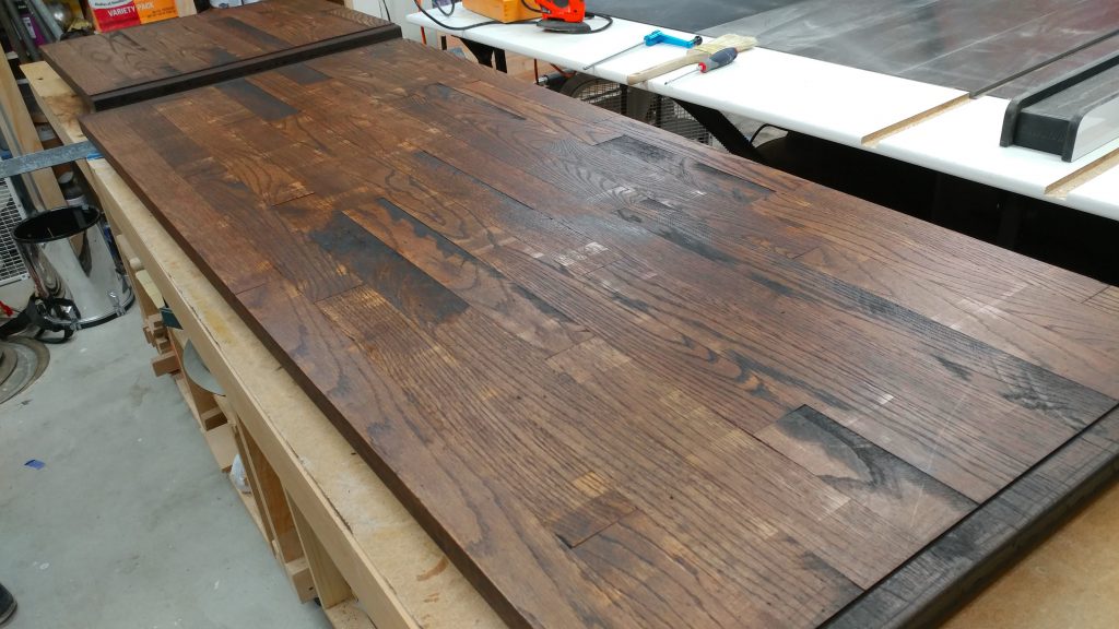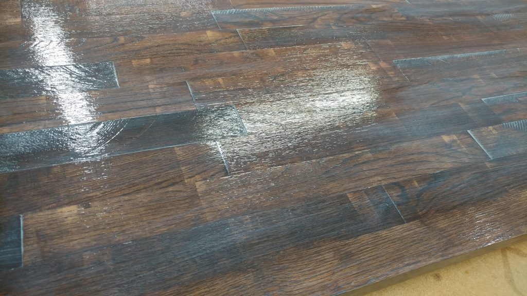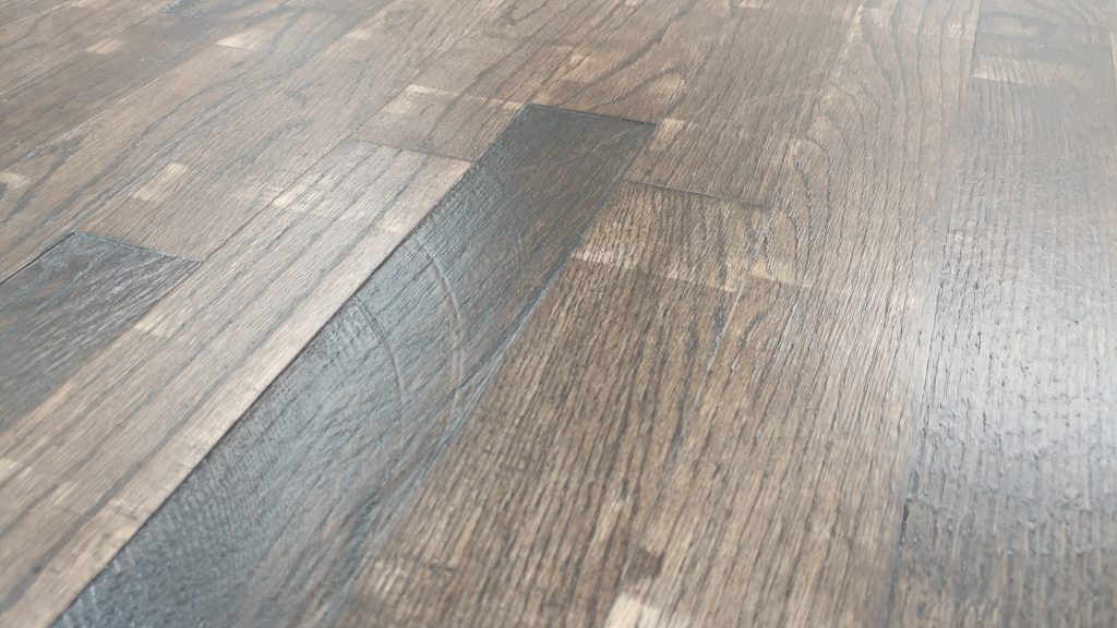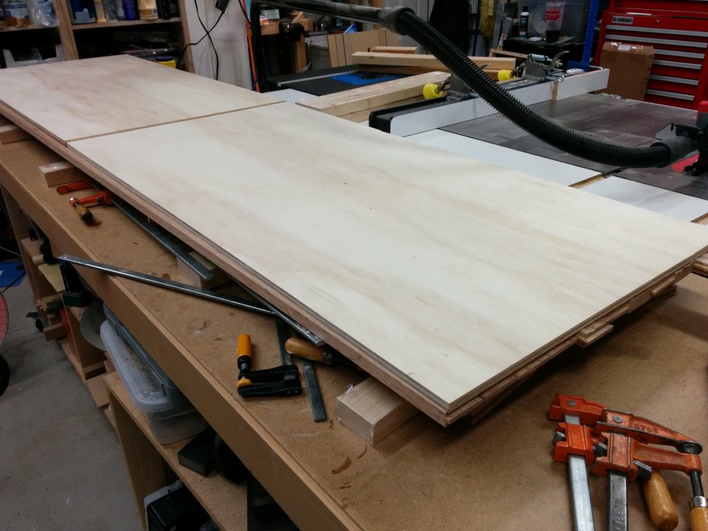

This is a continuation of Table Saw Modification – Router Table Enclosure: Part 1 – Carcase and Table Saw Modification – Router Table Enclosure: Part 2 – Laminate.
A while back I converted my side extension table into a router table. Although not strictly necessary, I am going to enclose the router and add dust collection, while also creating much-needed storage and enclosing the electrical.
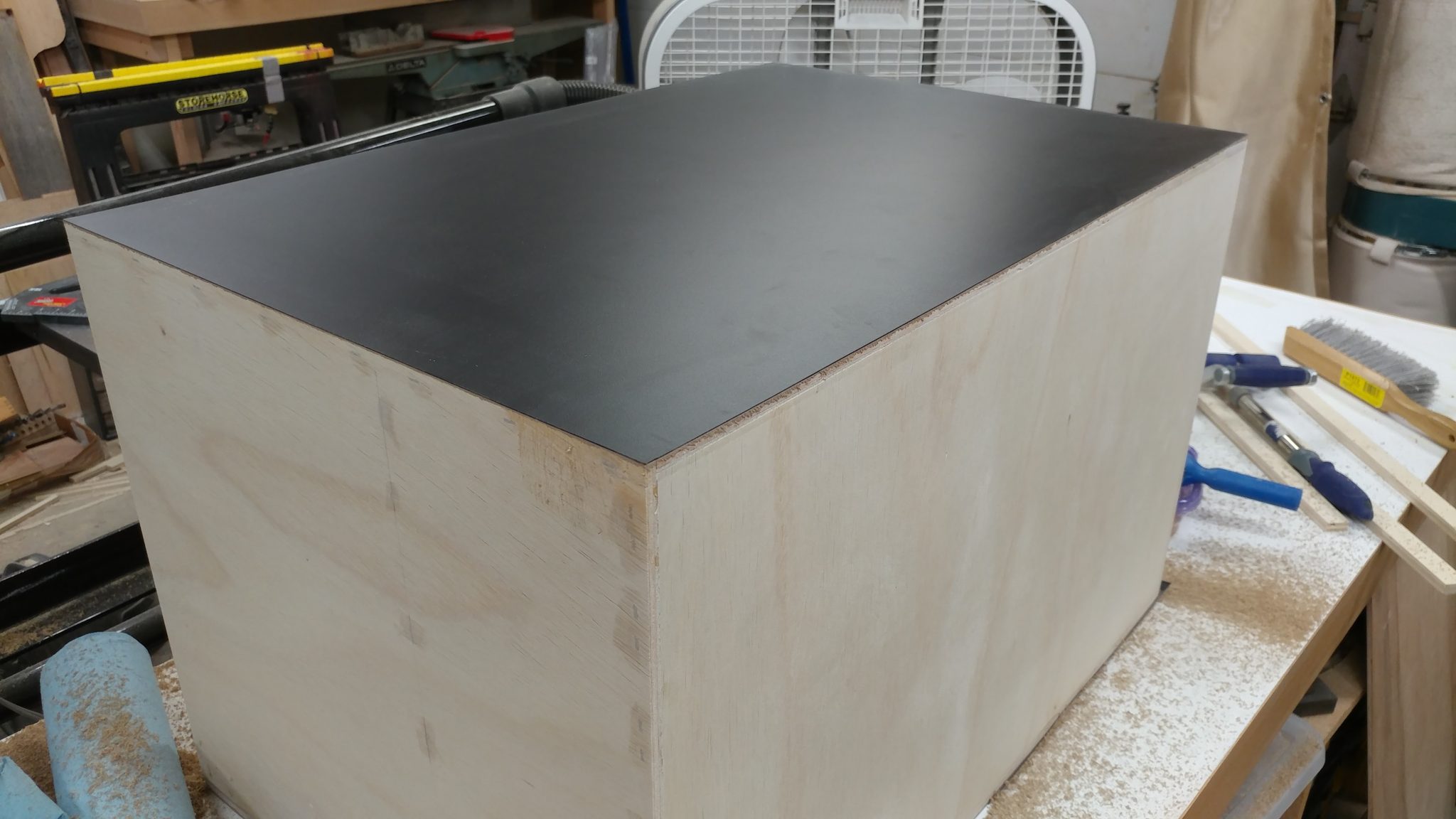
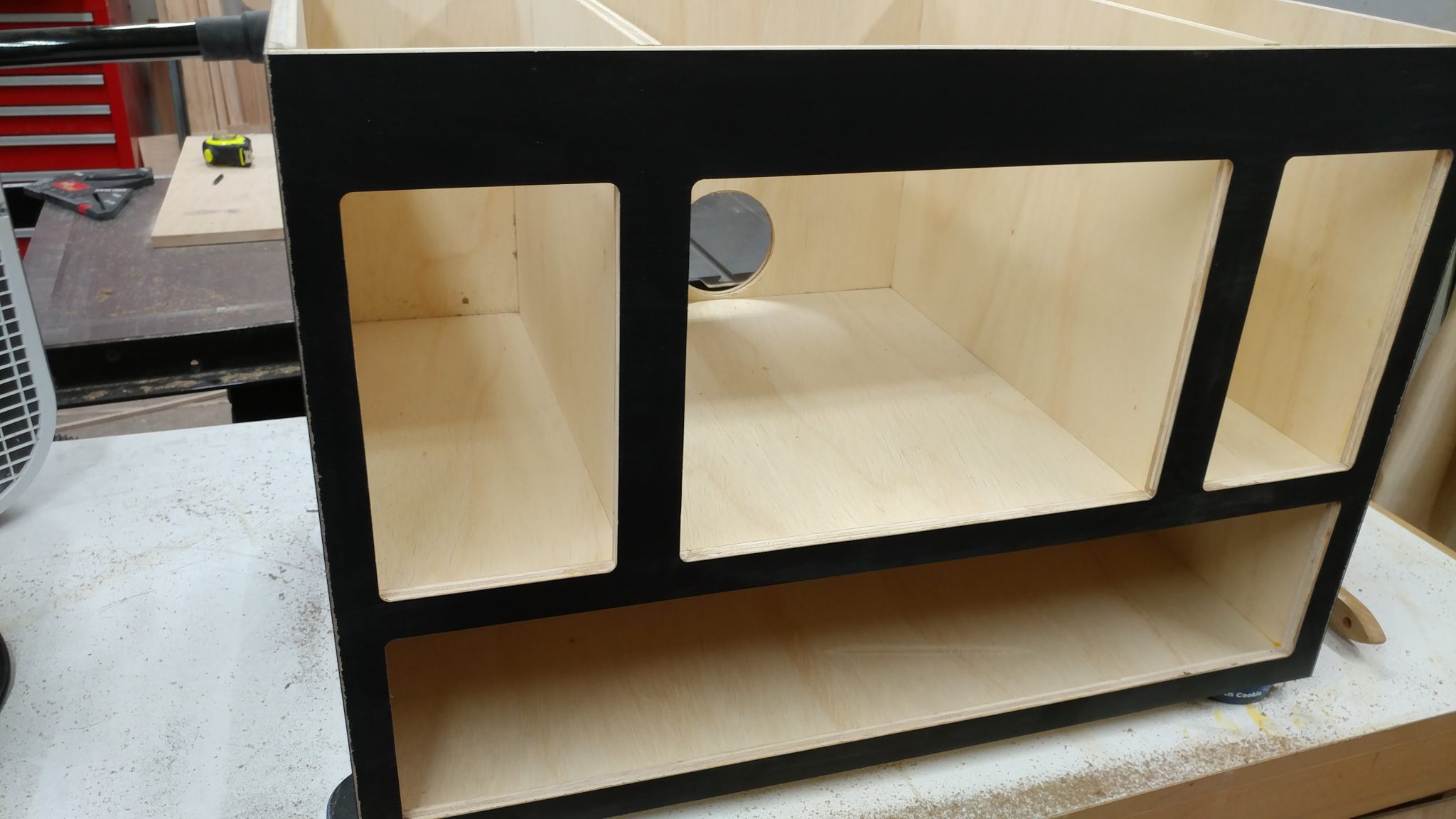
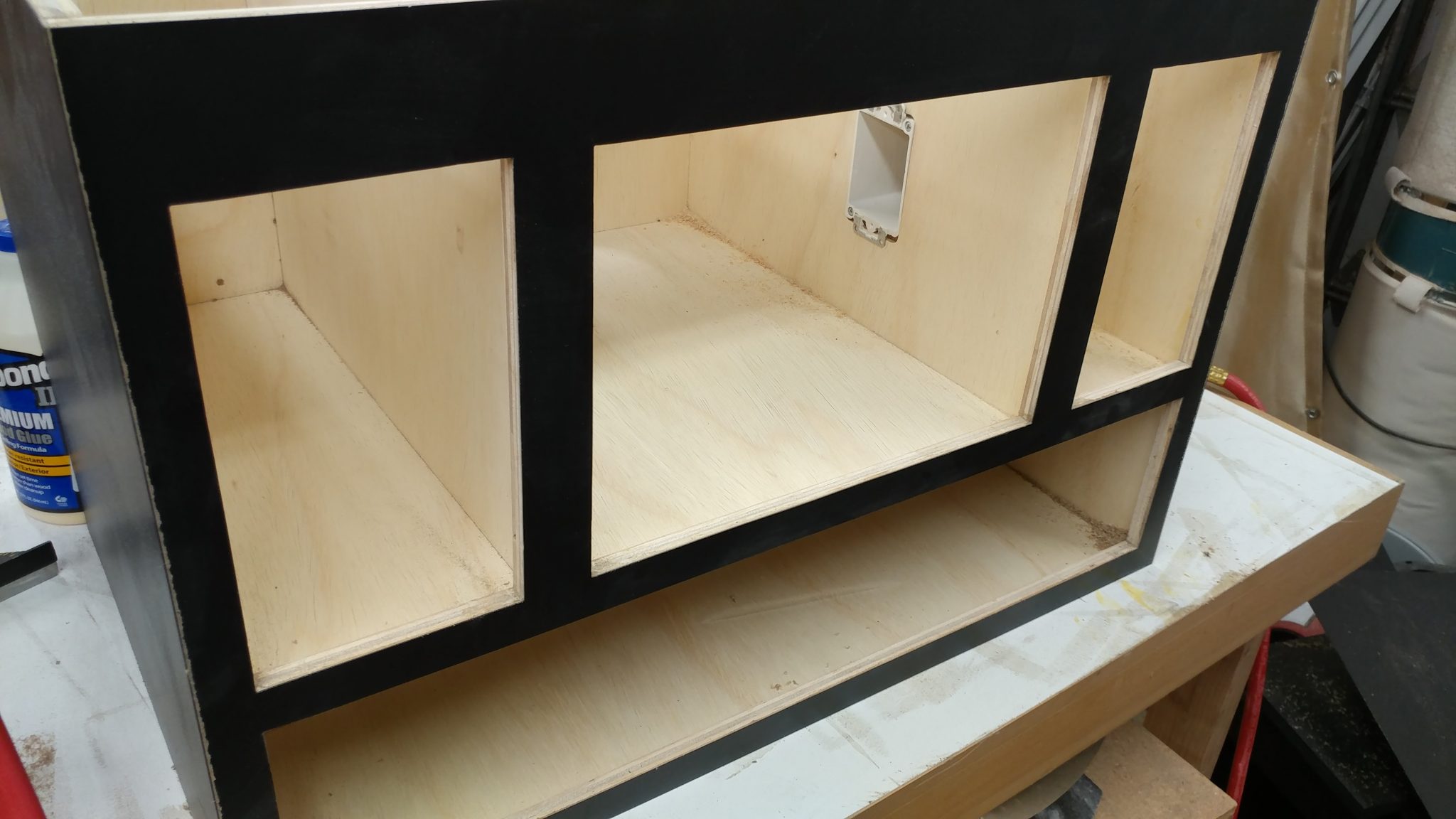
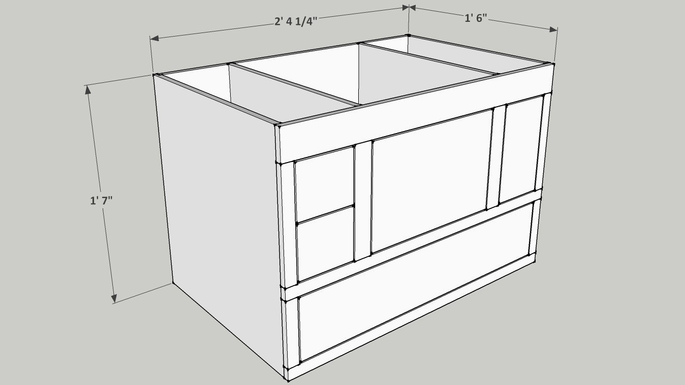
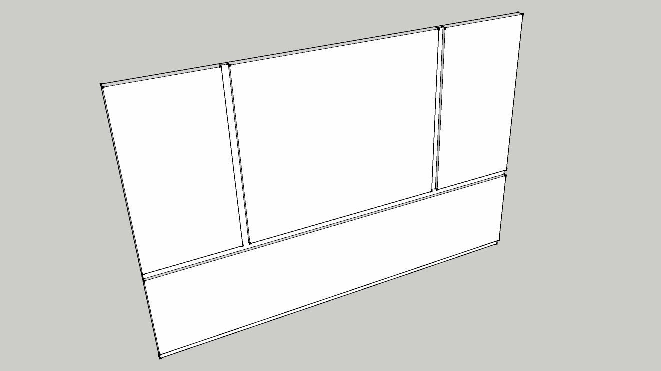
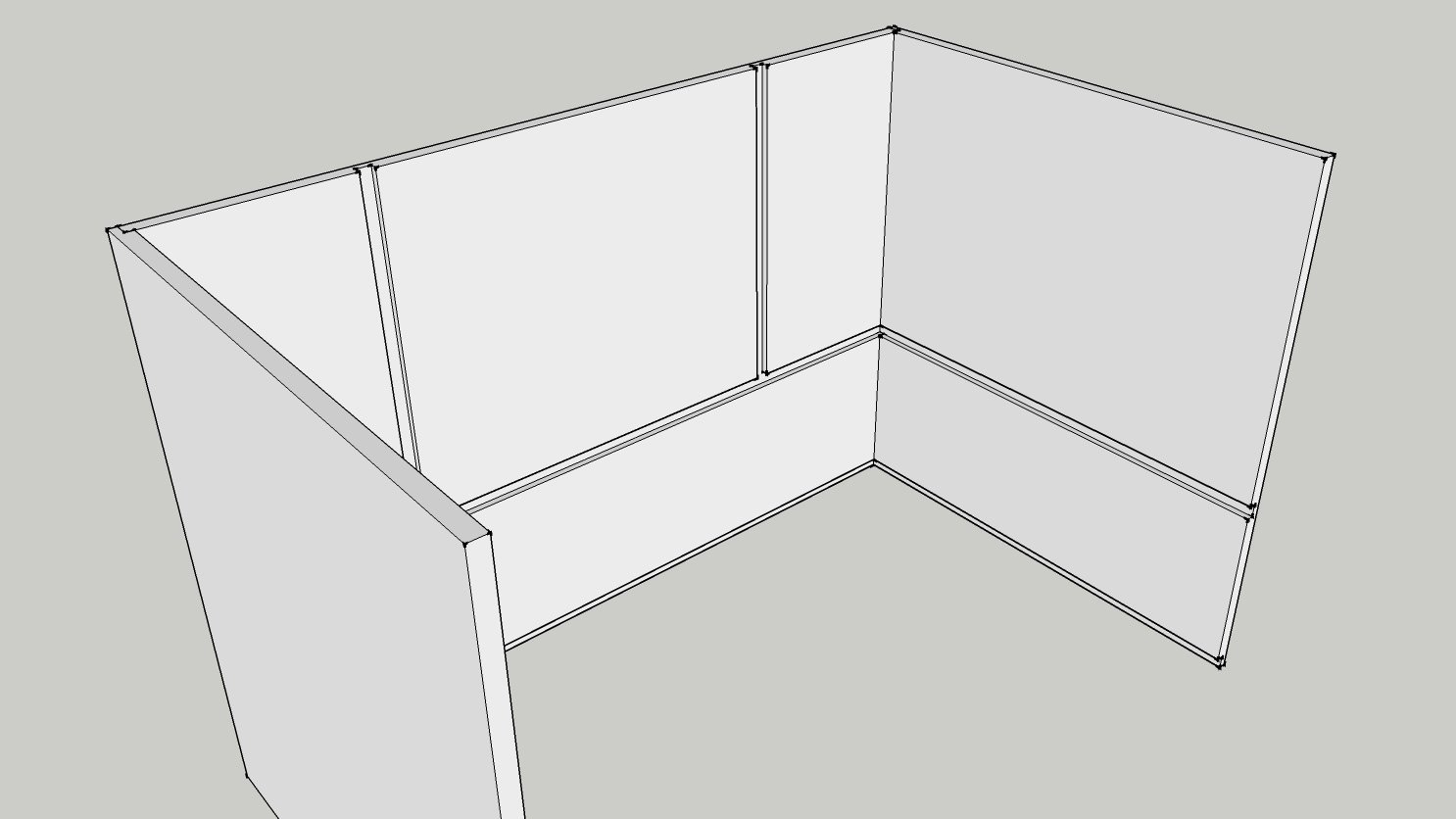
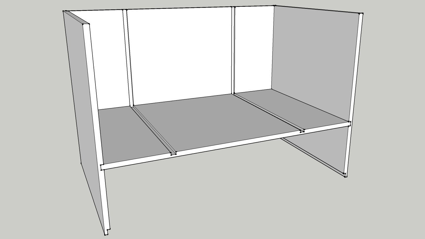
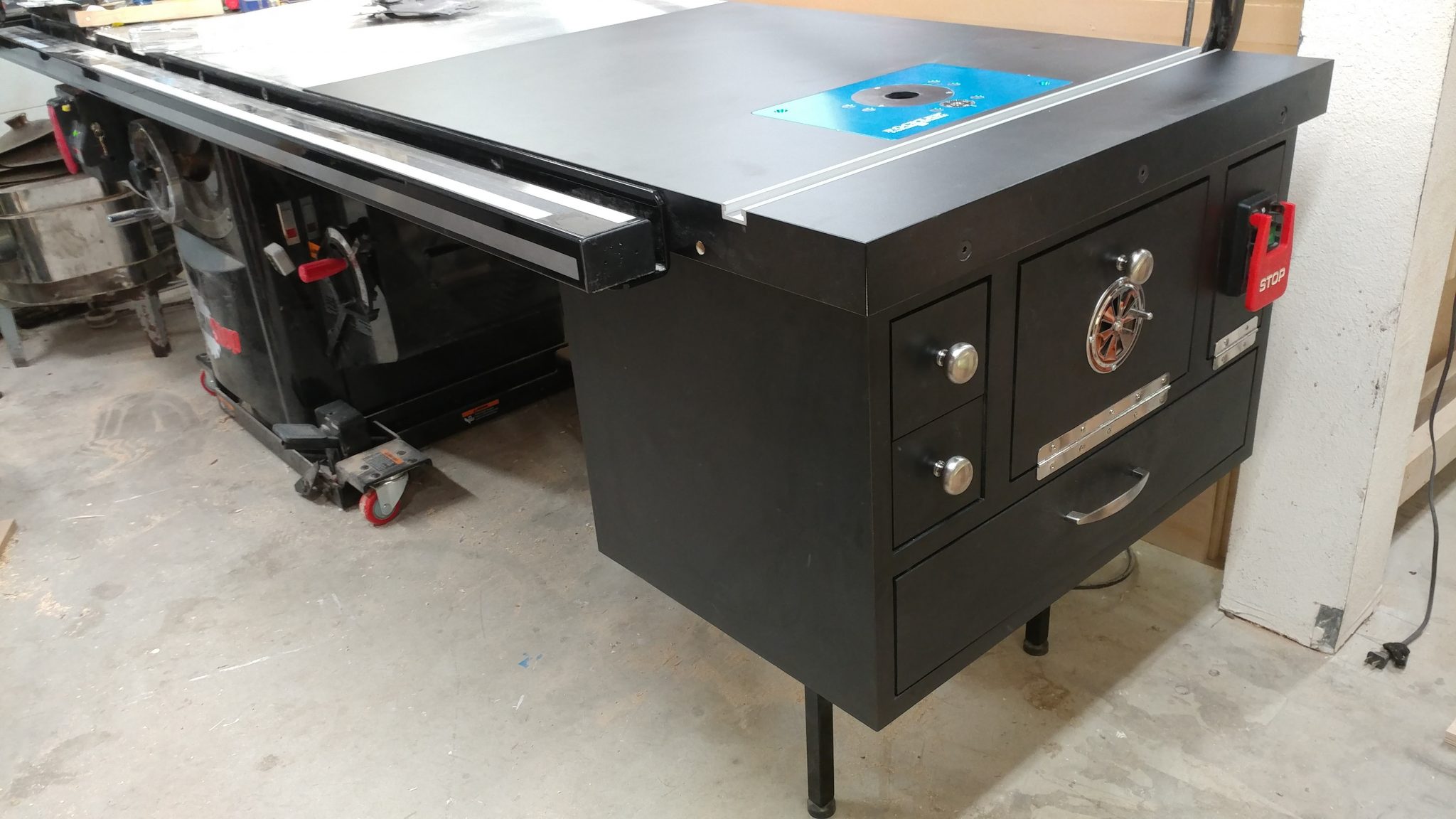
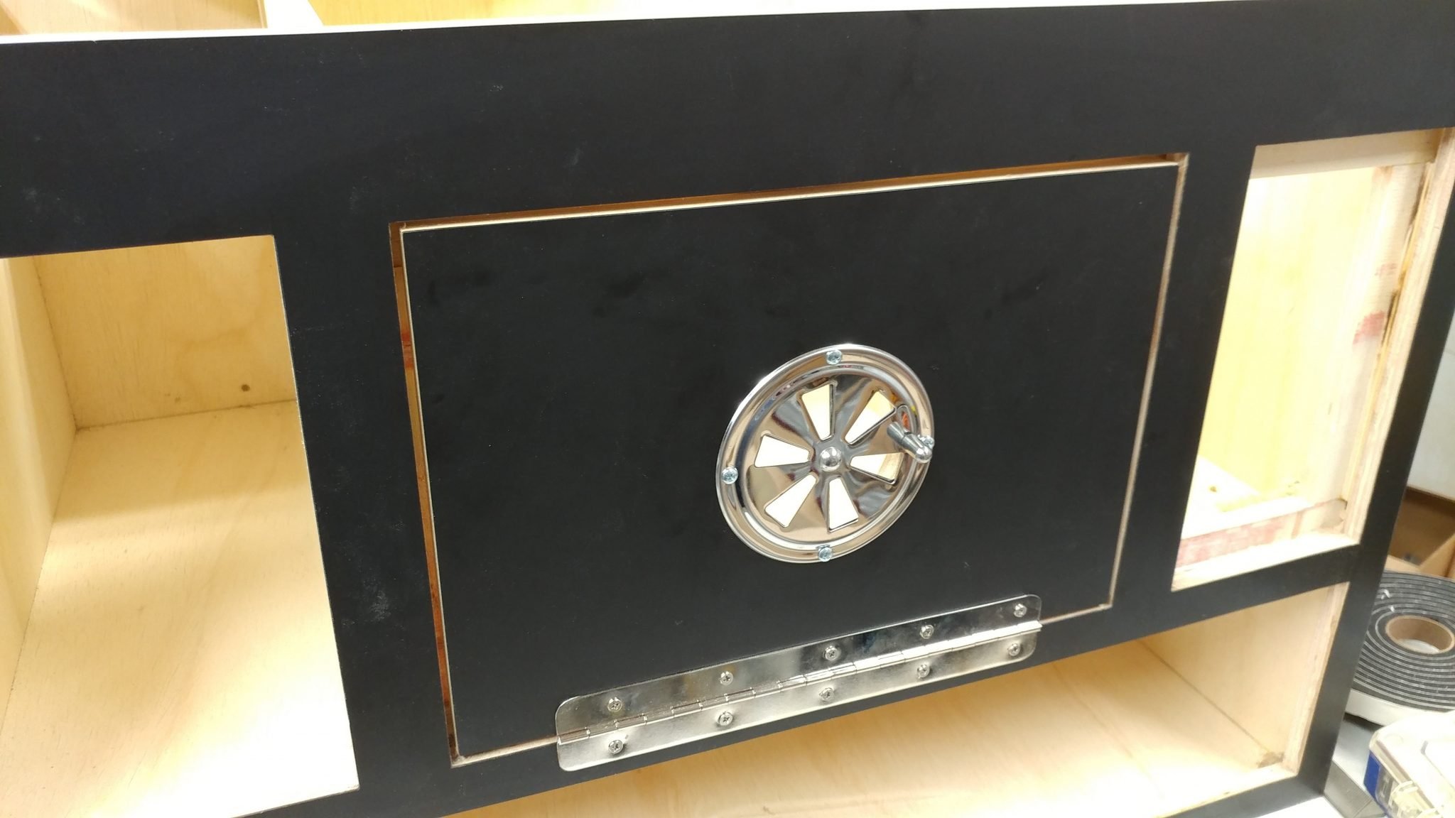
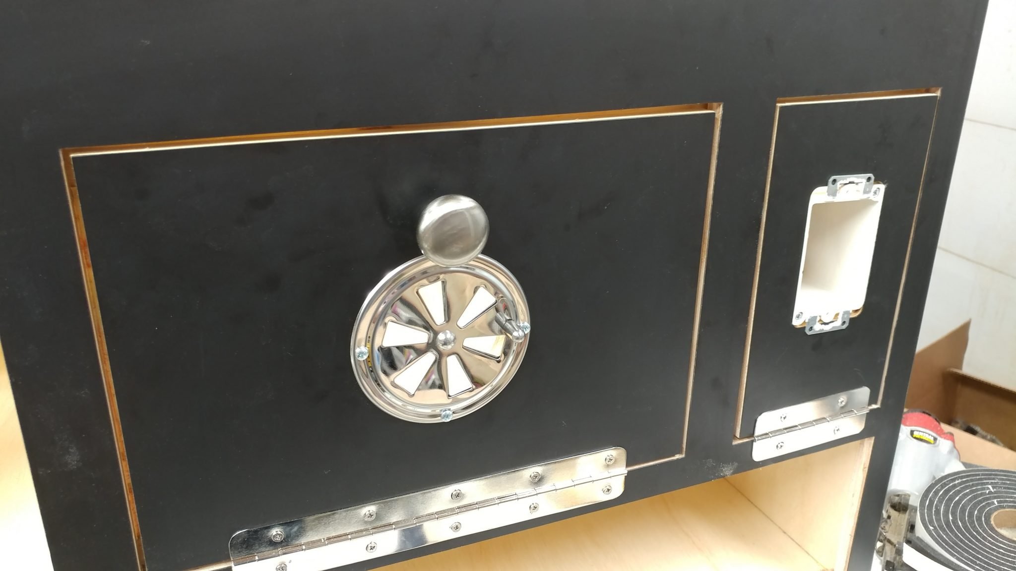
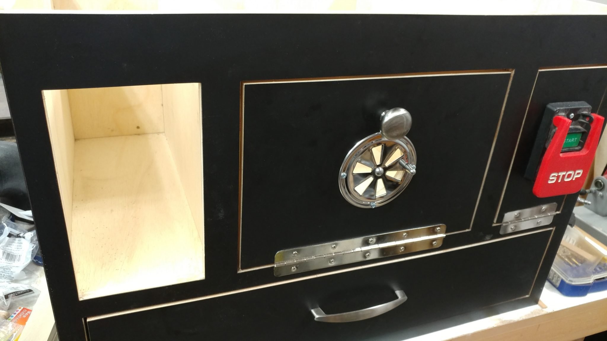
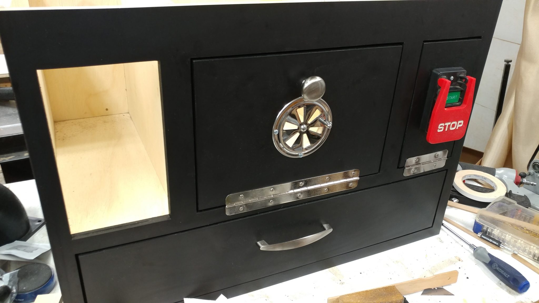
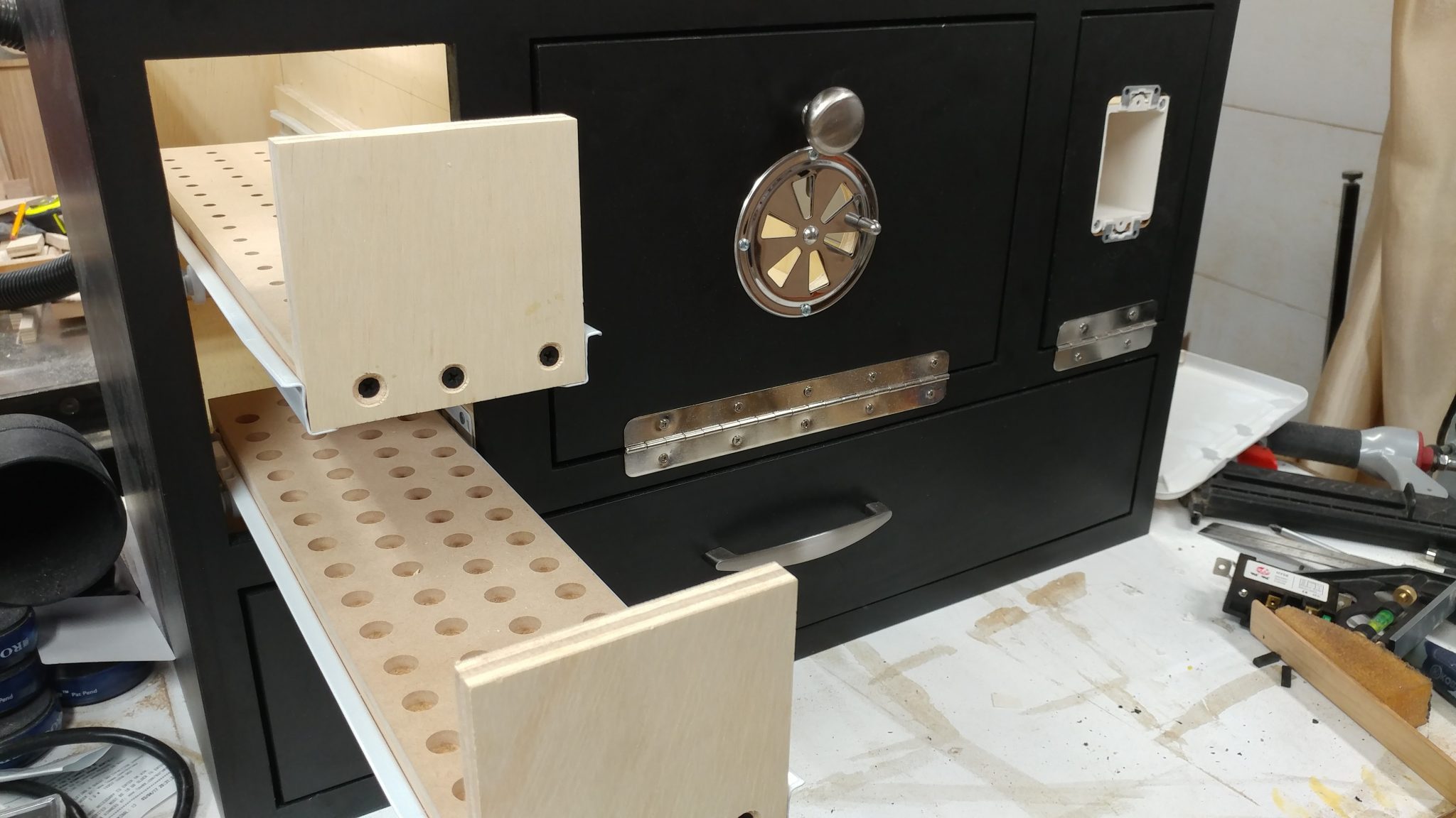
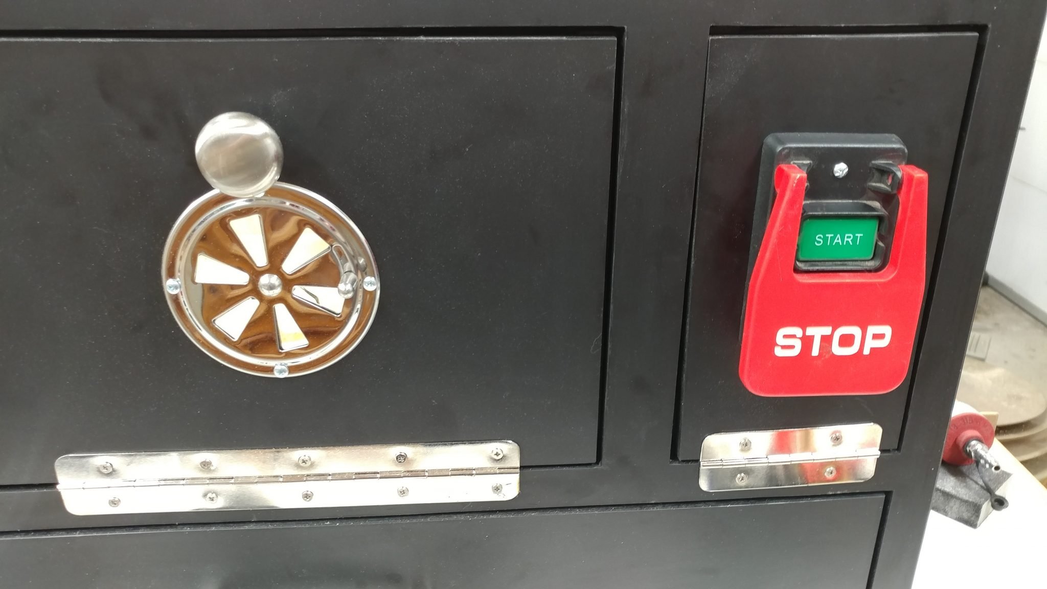
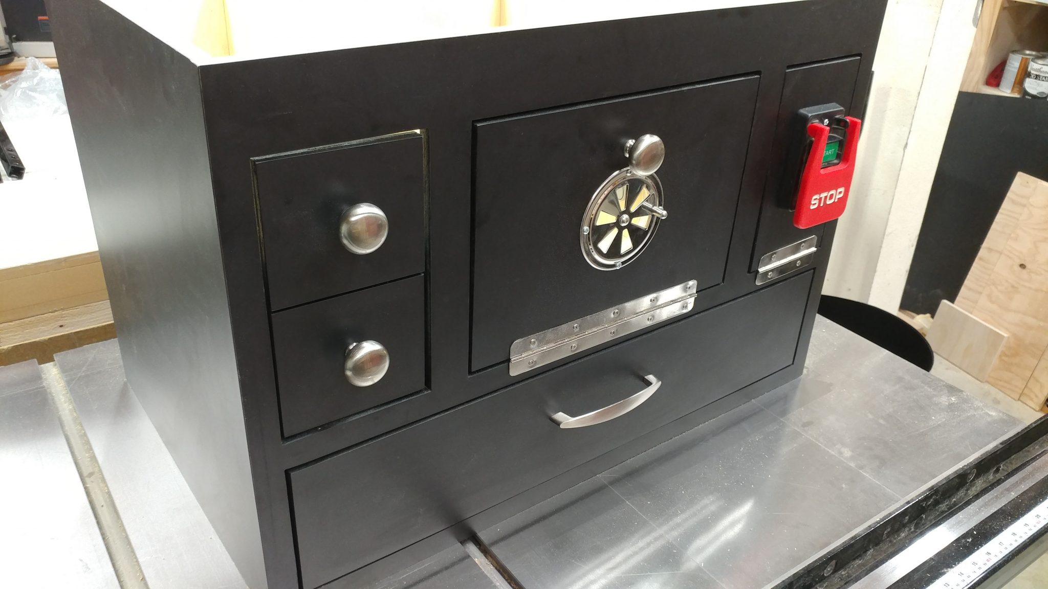
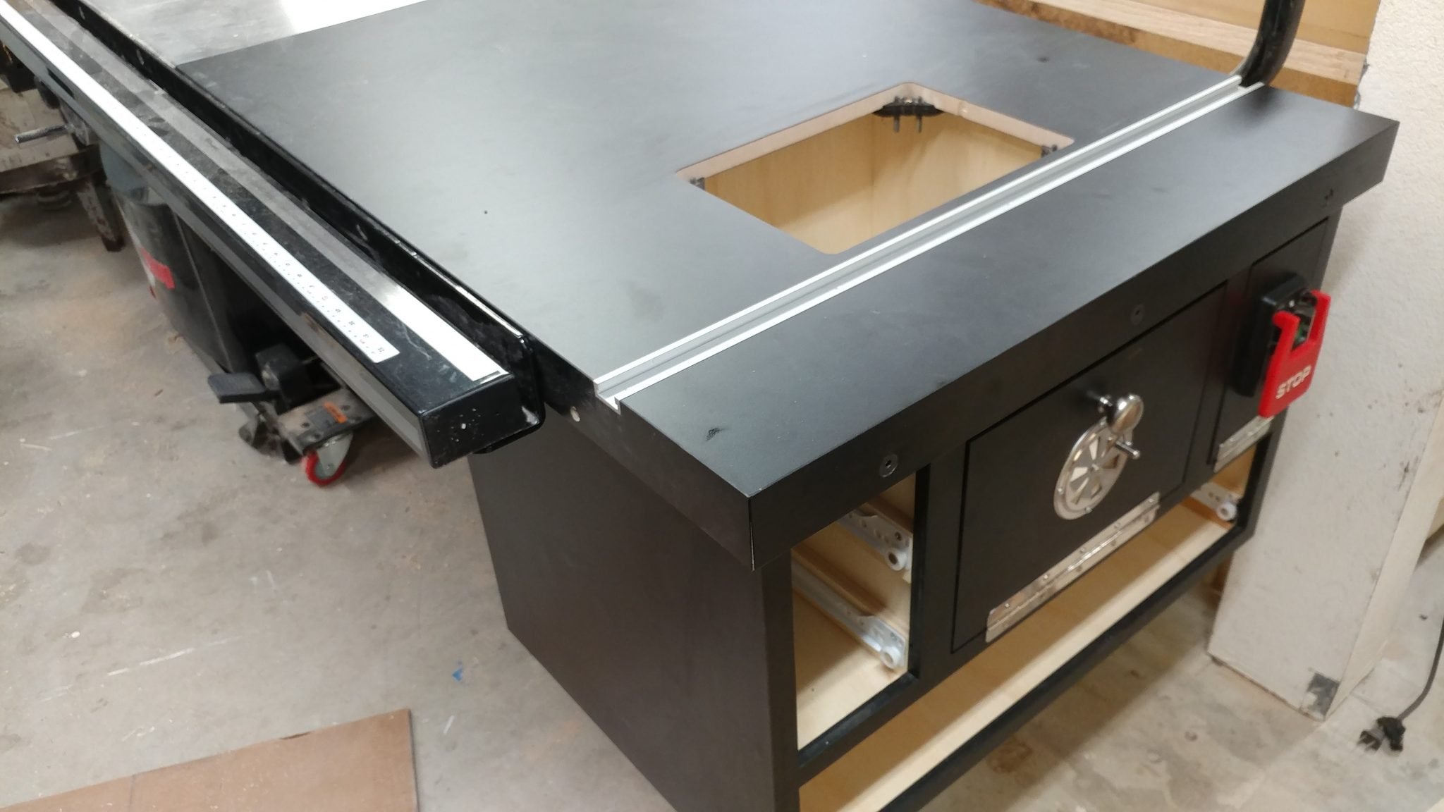
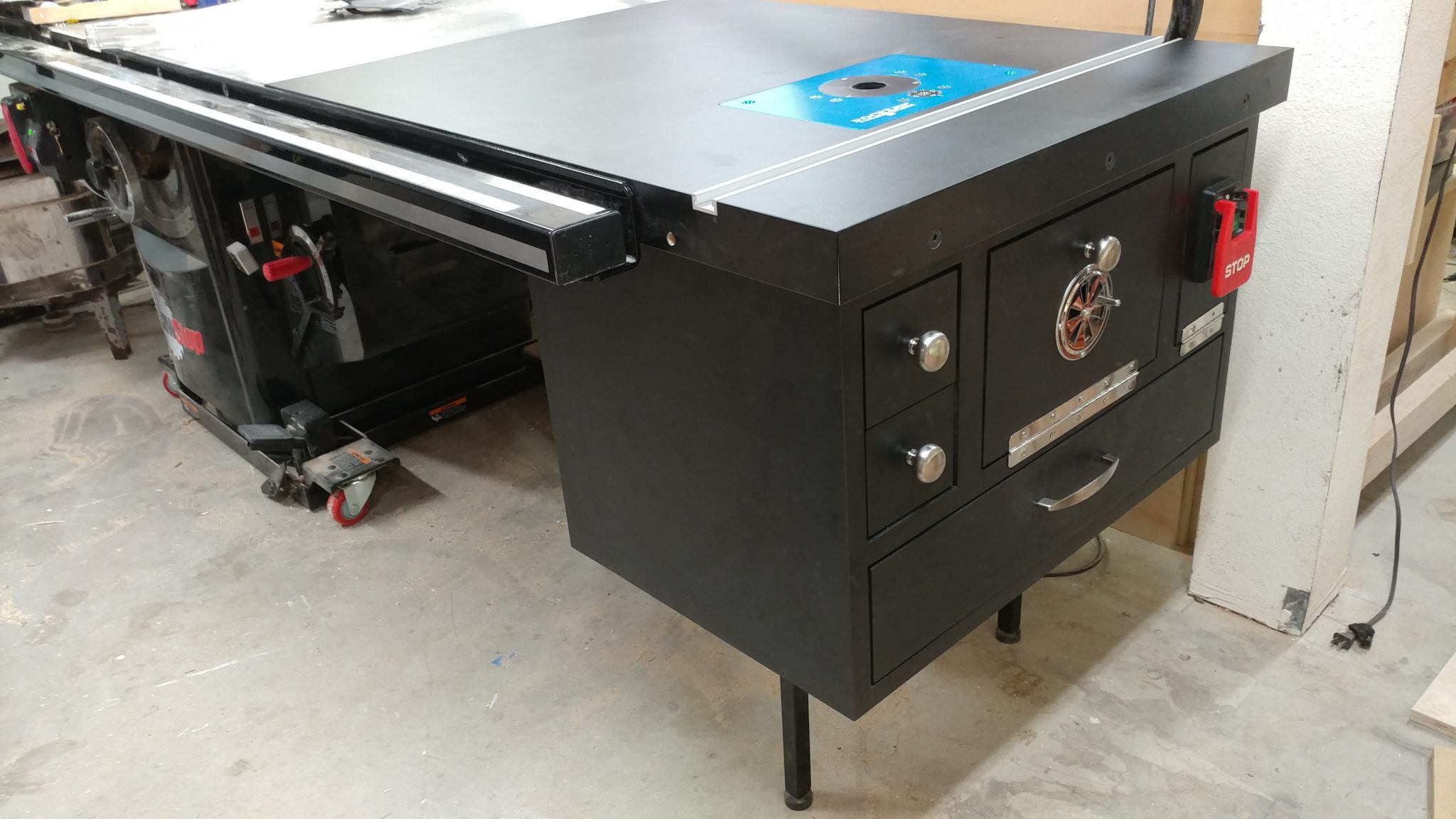
So you can see what I have in mind, here’s a sneak peek of the finished enclosure.
Attaching the doors and drawers
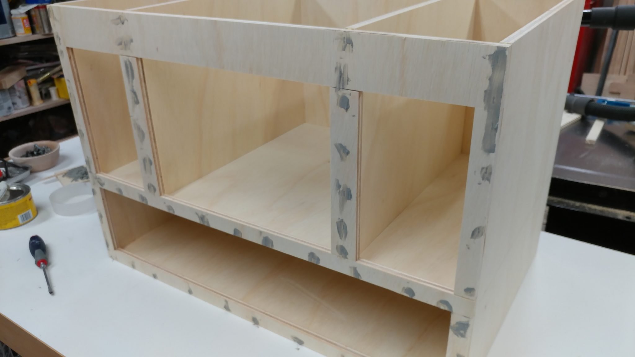
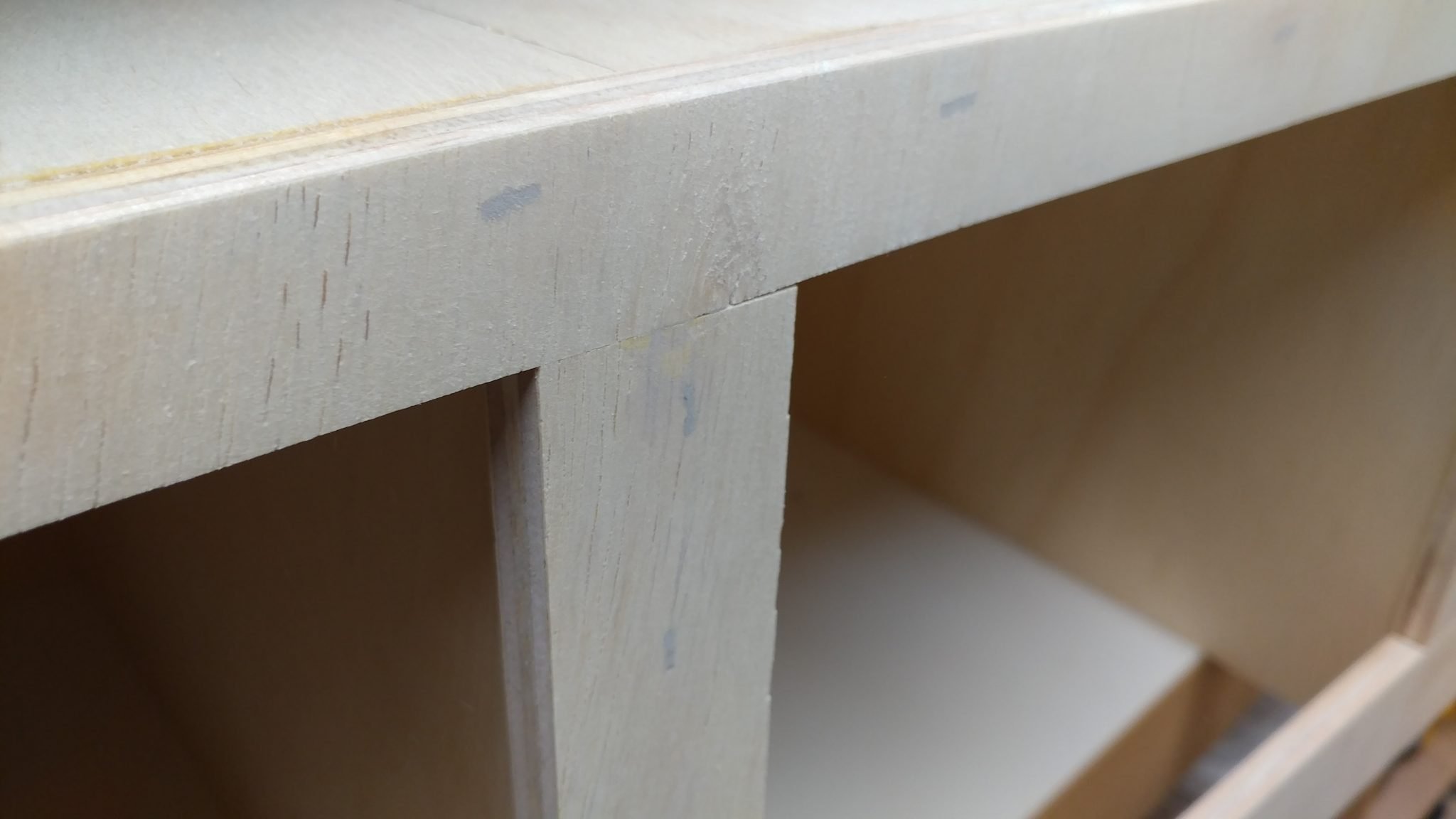
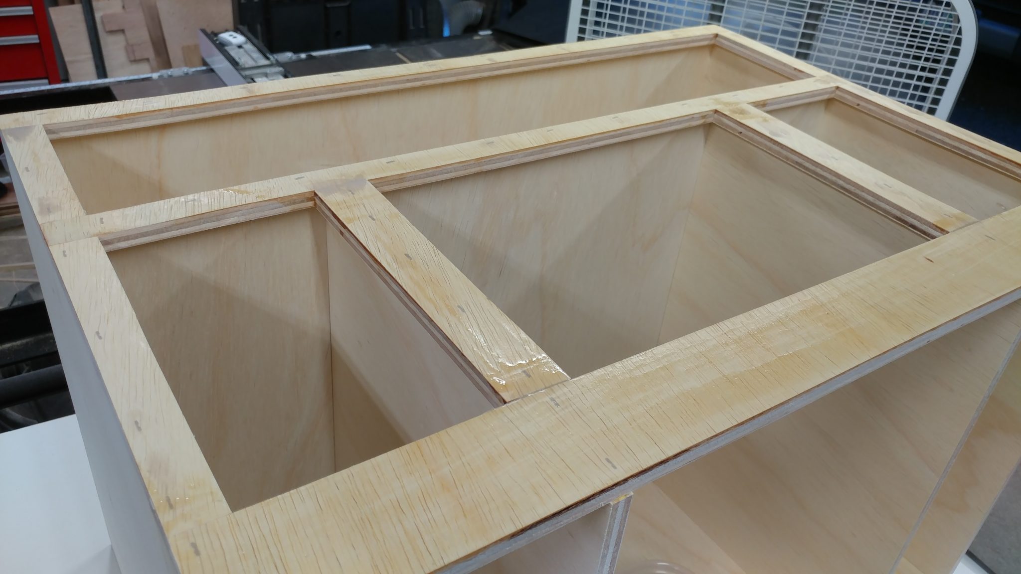
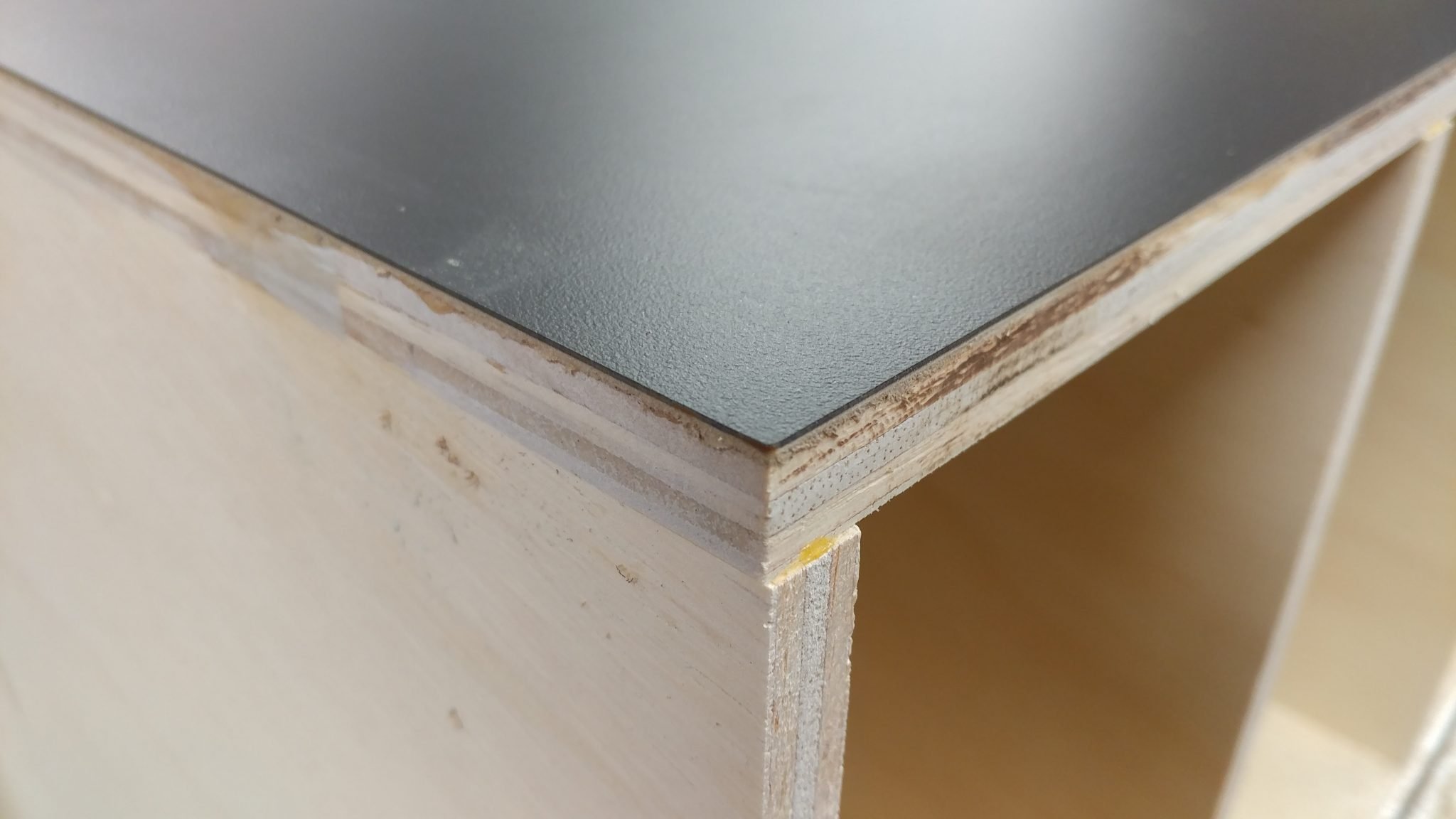
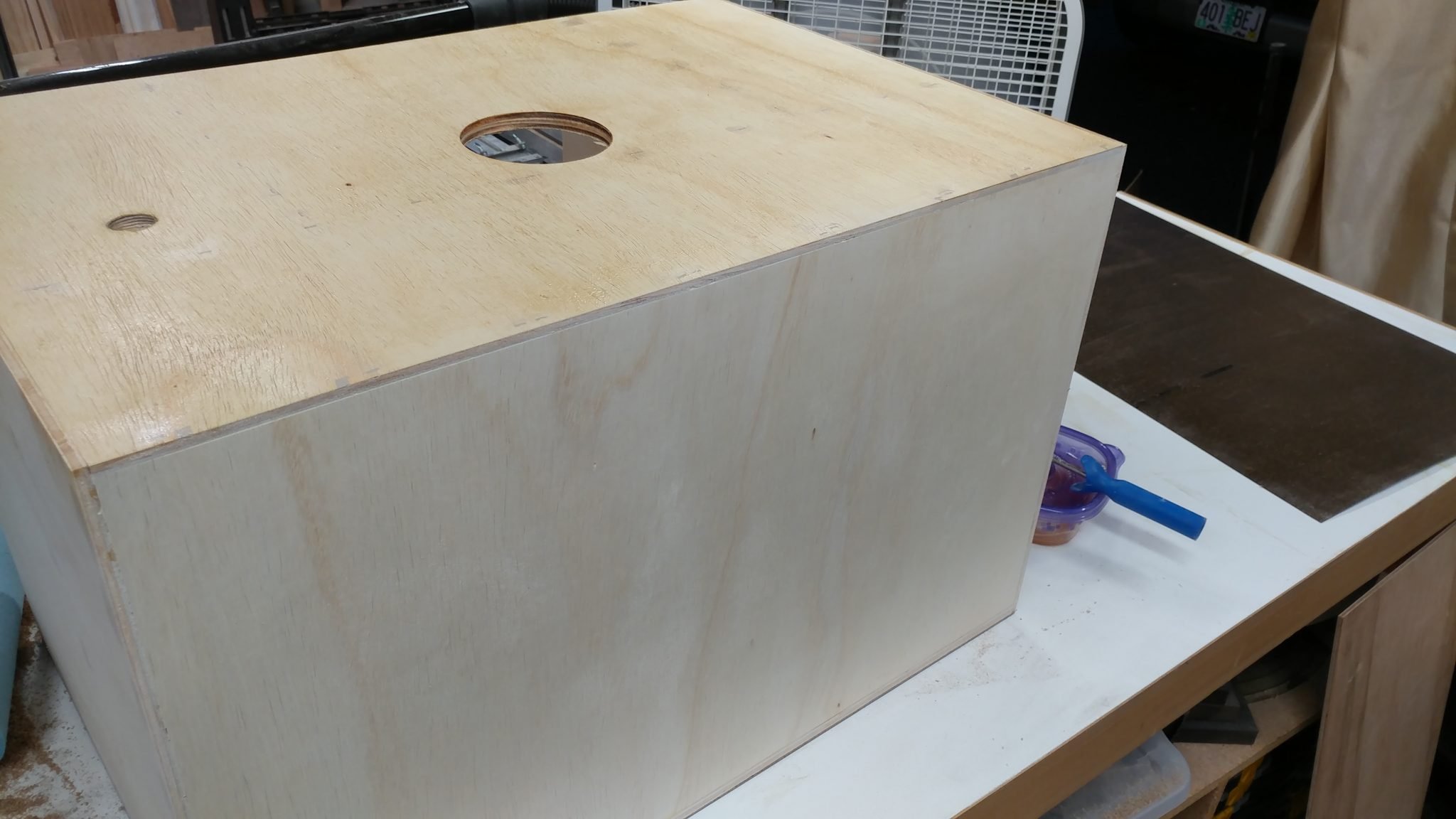
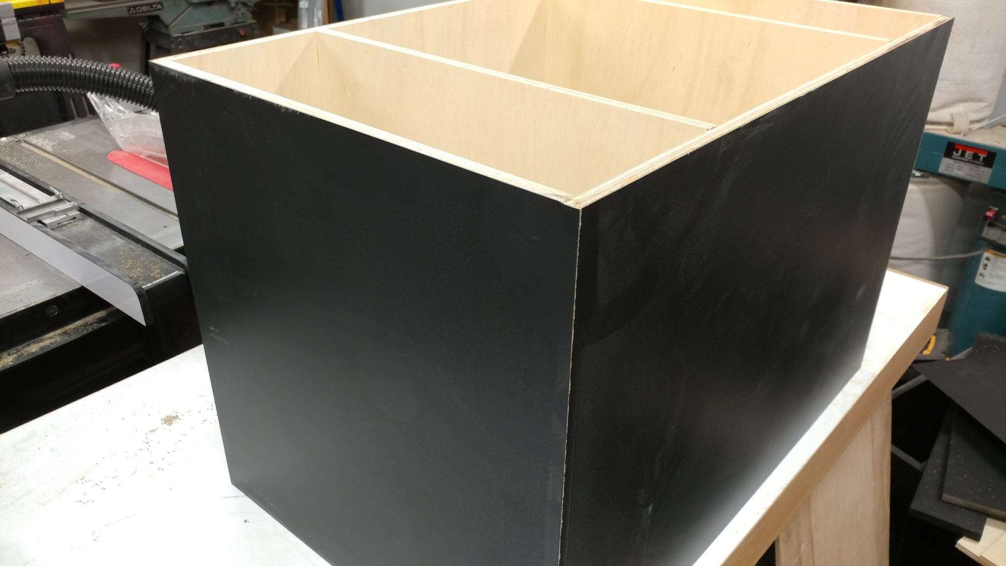
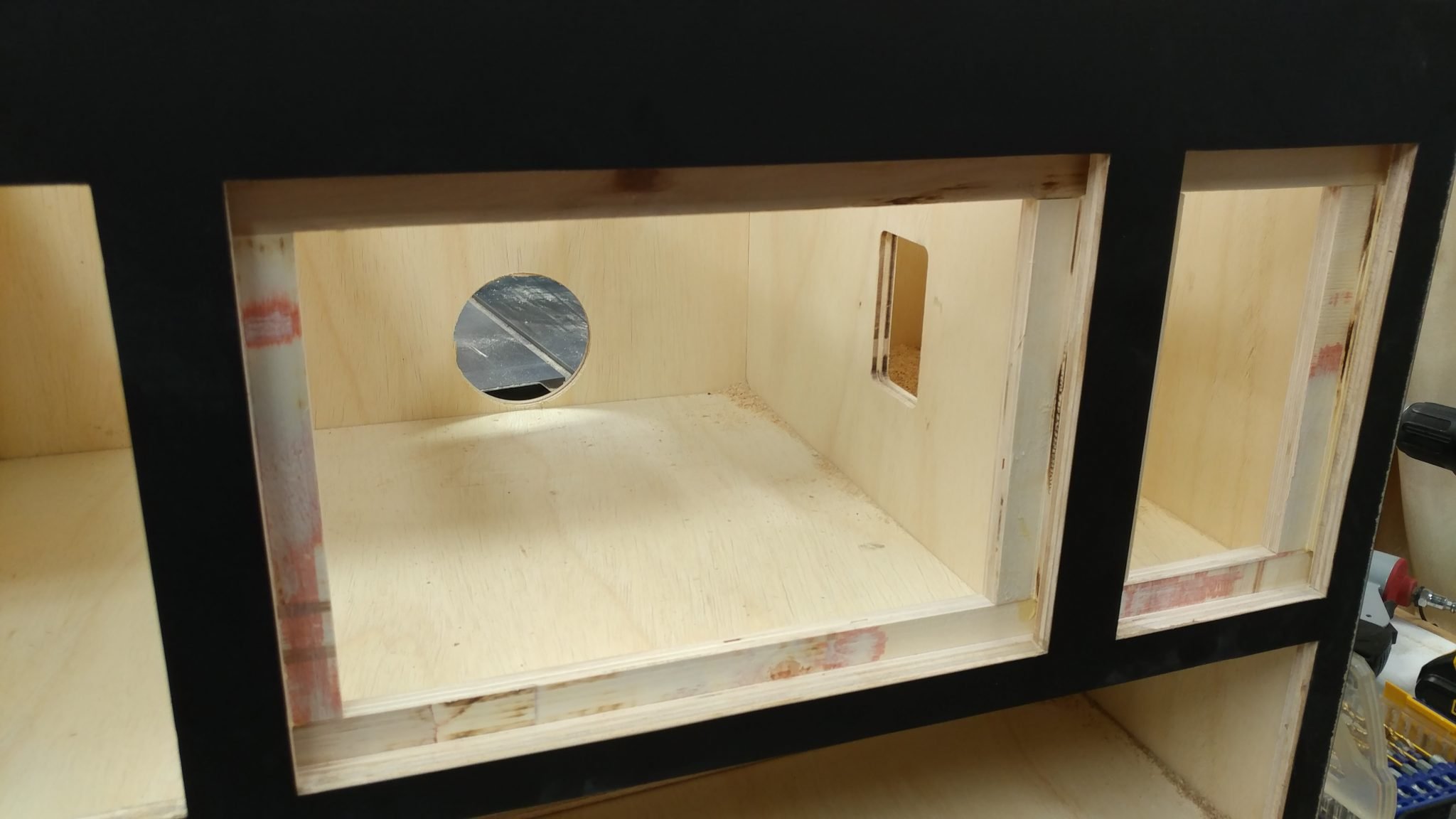
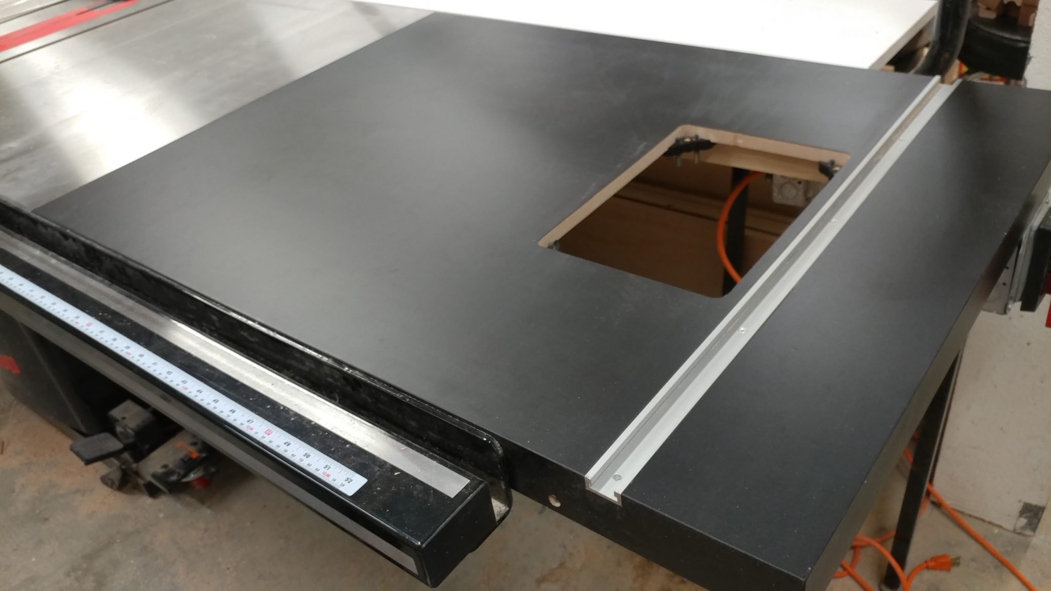
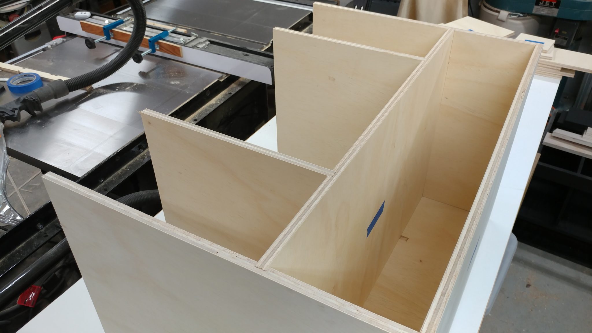
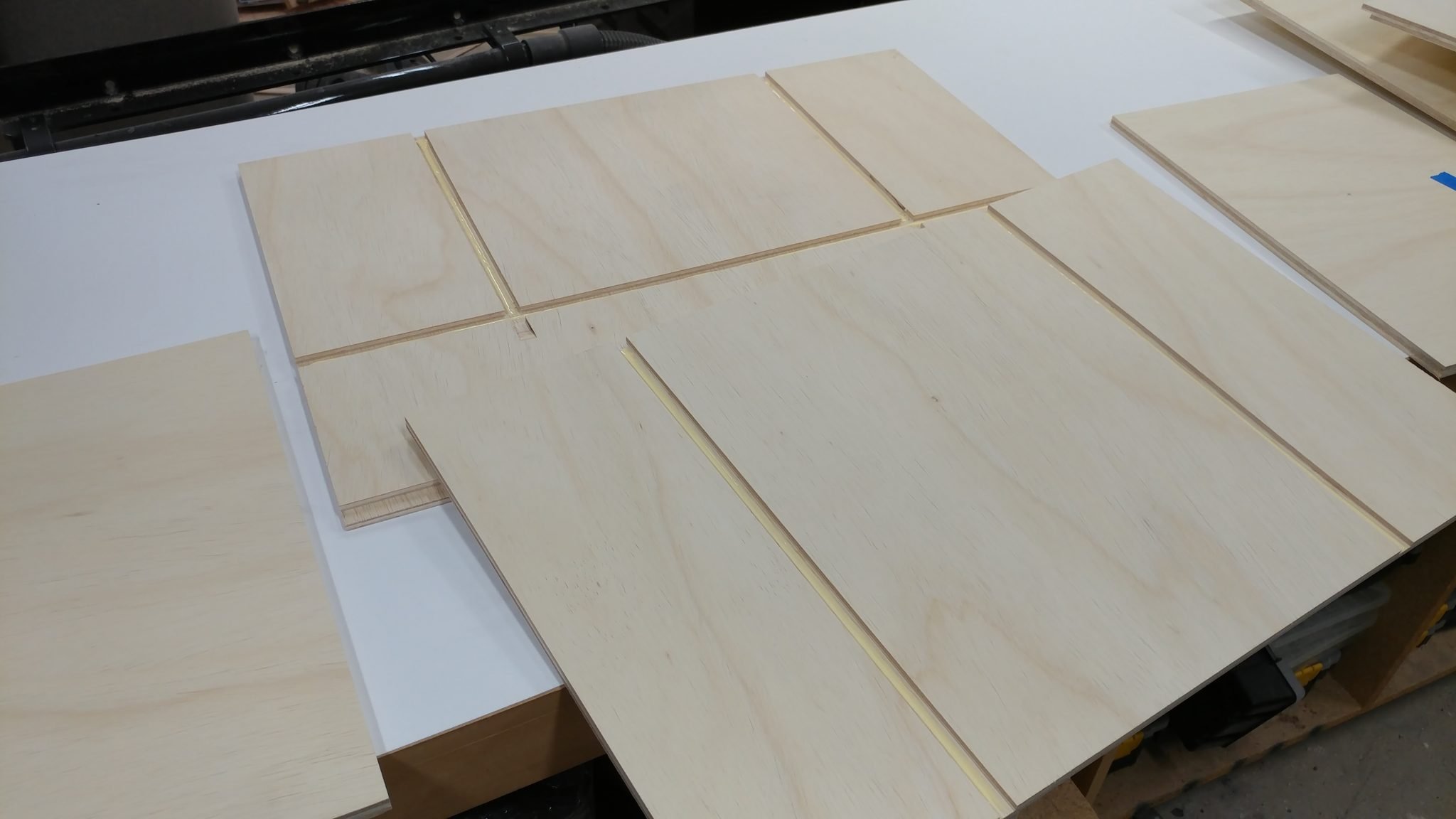
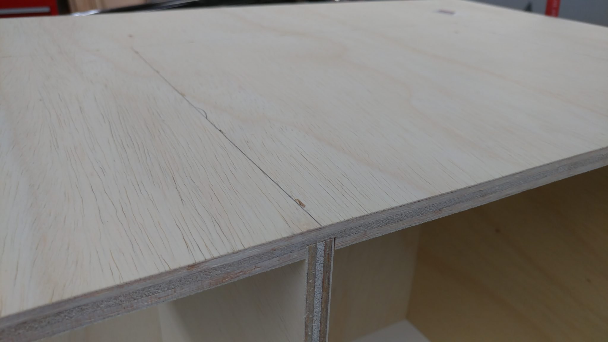
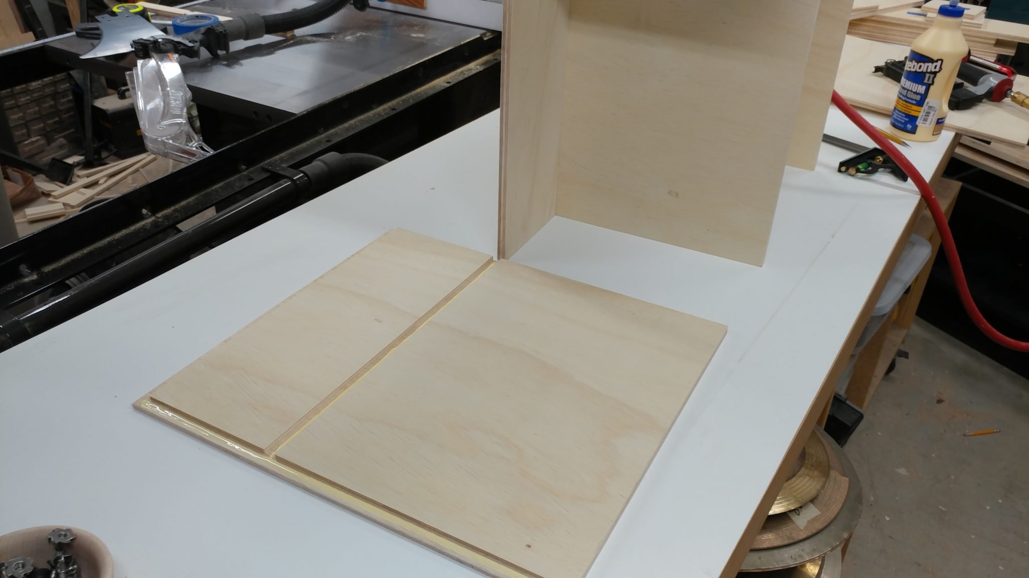
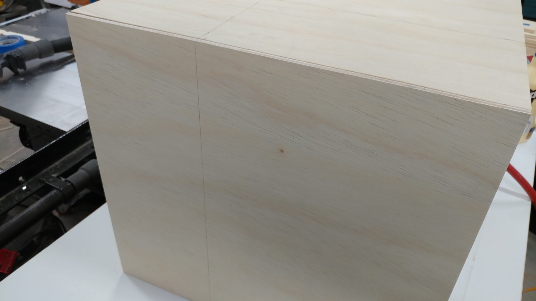
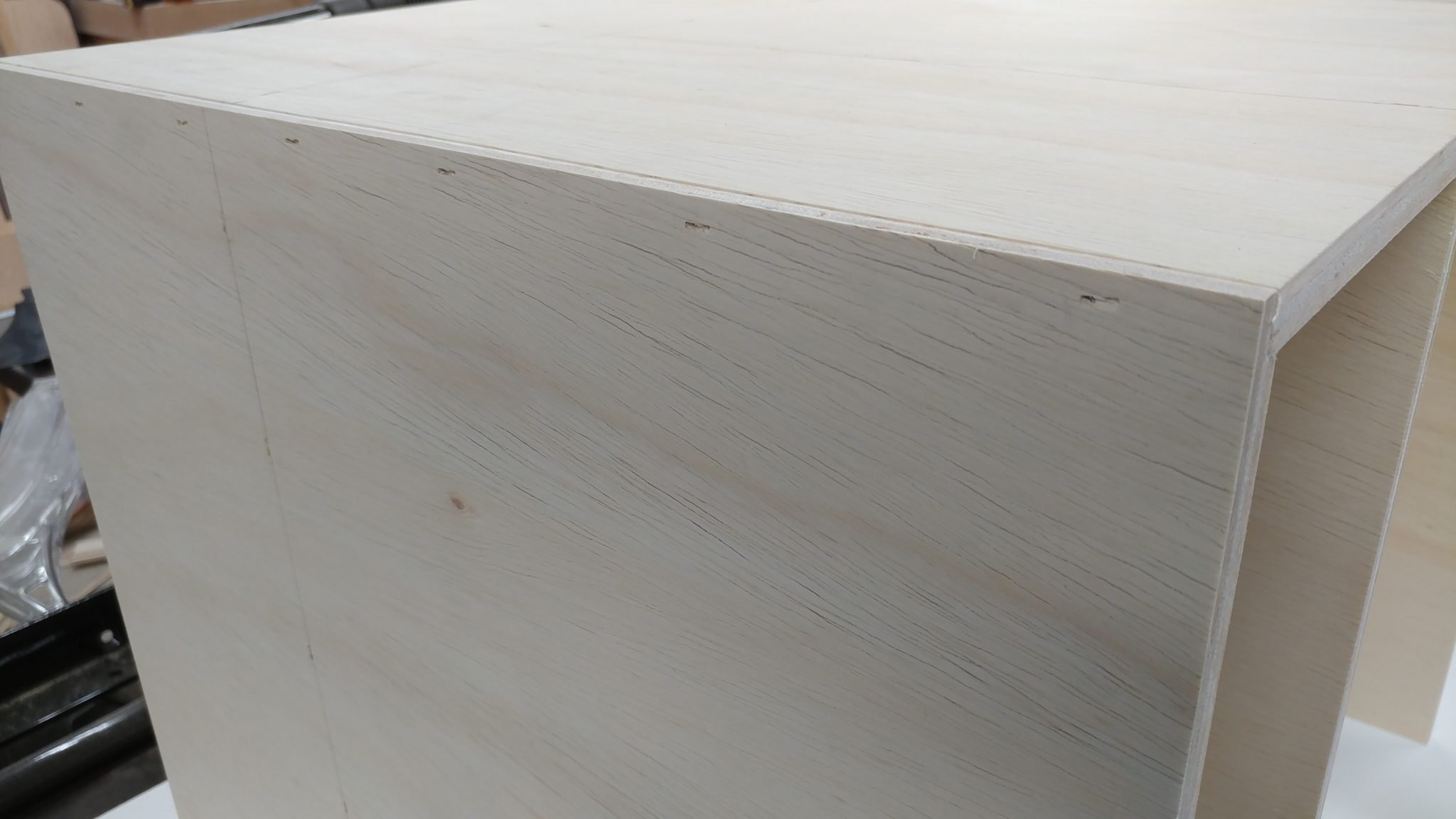
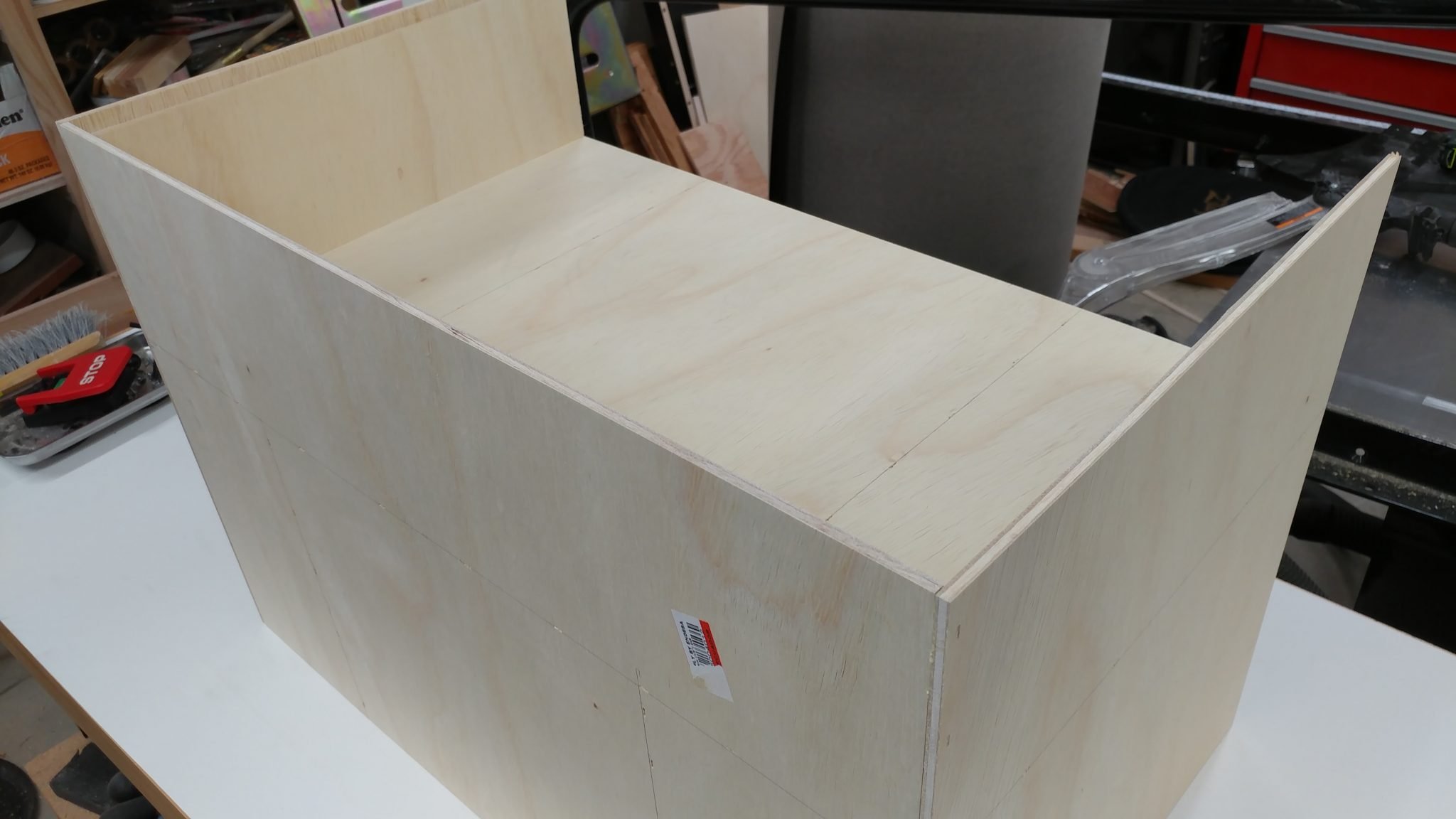
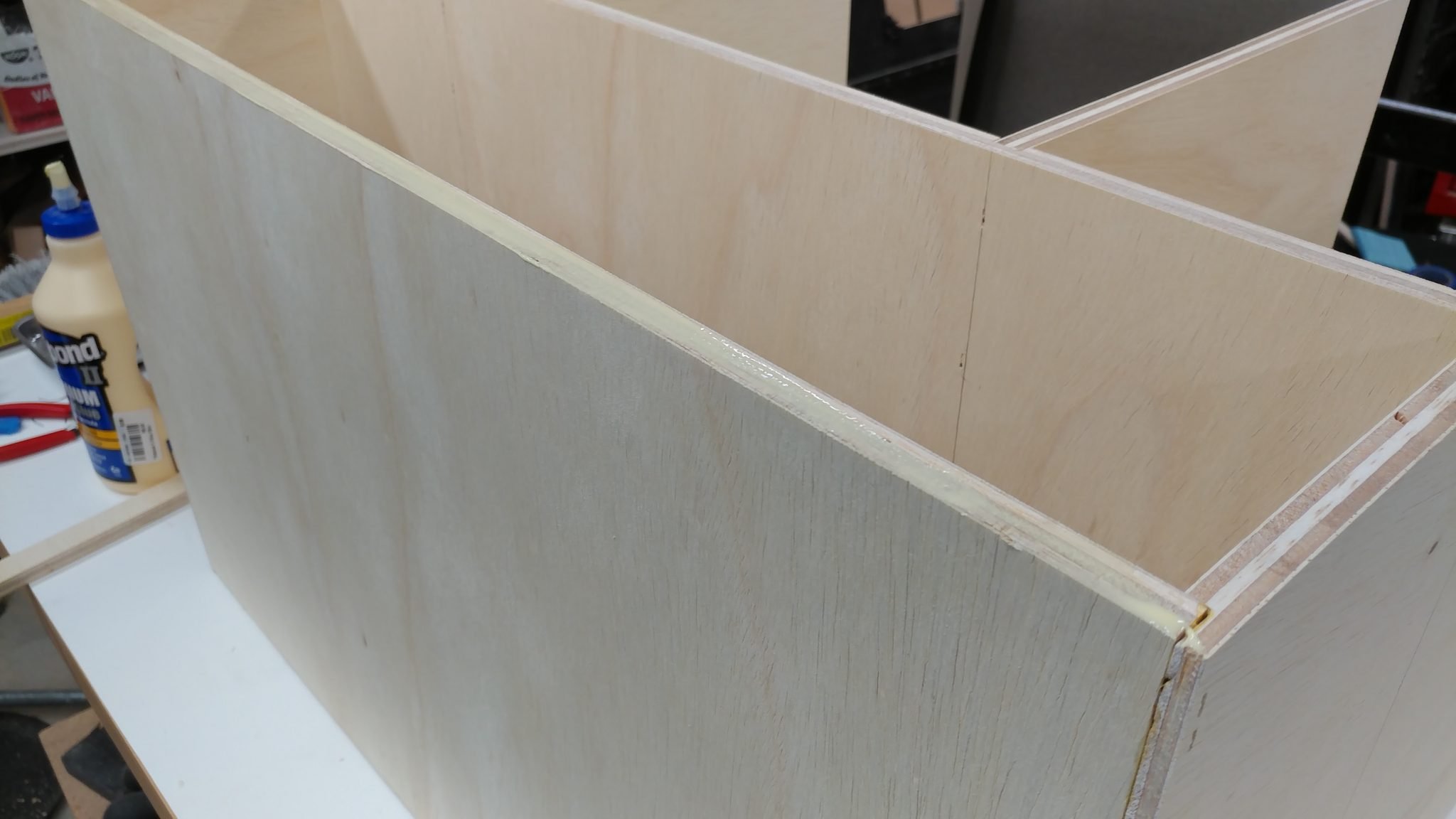
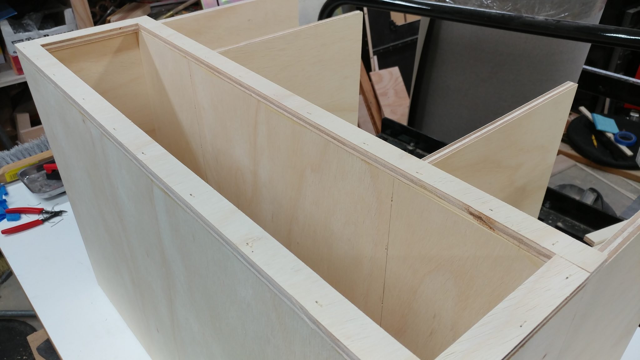
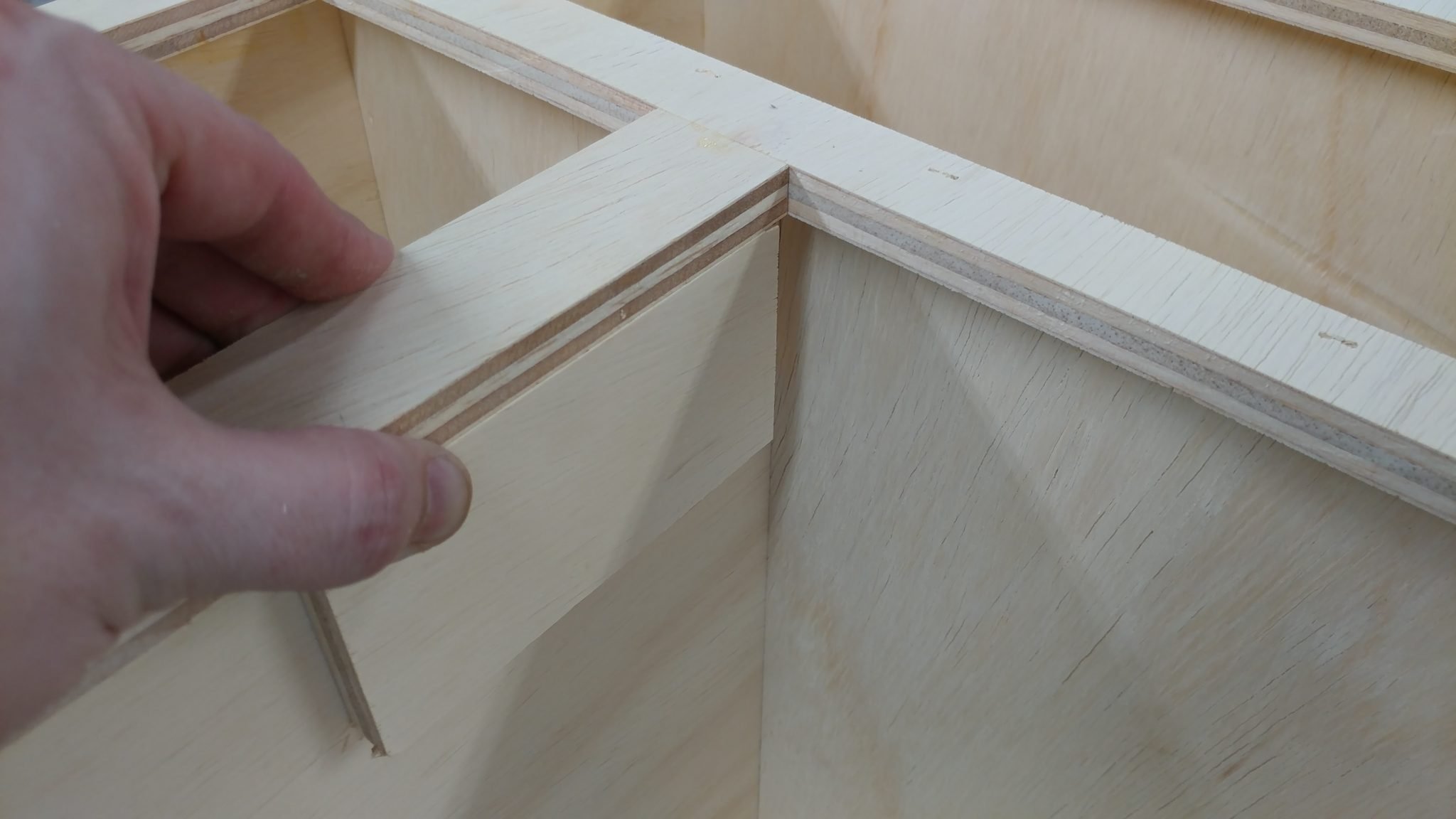
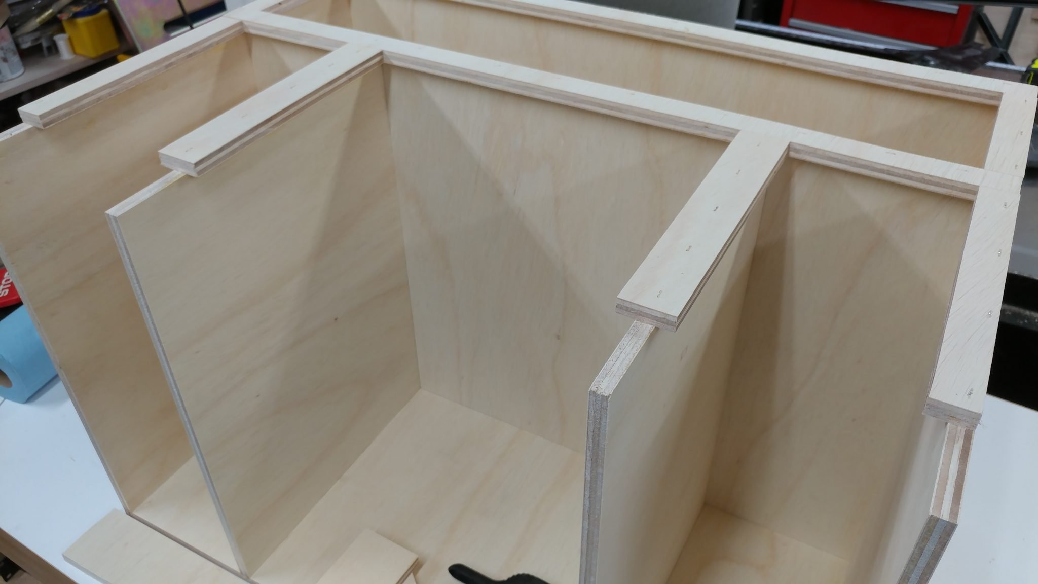
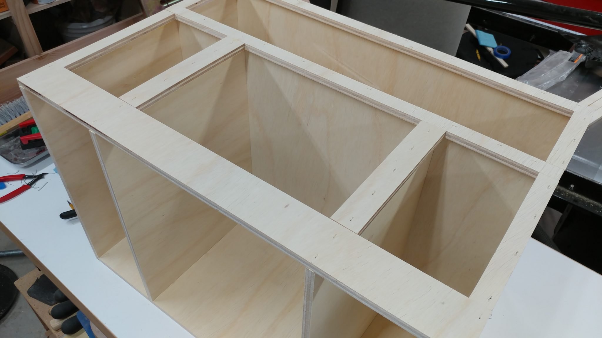
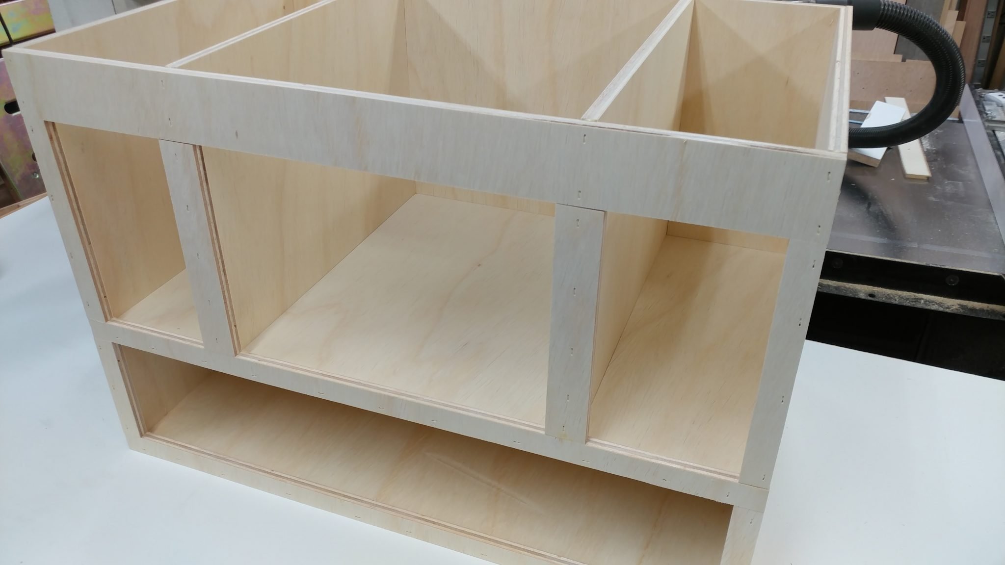
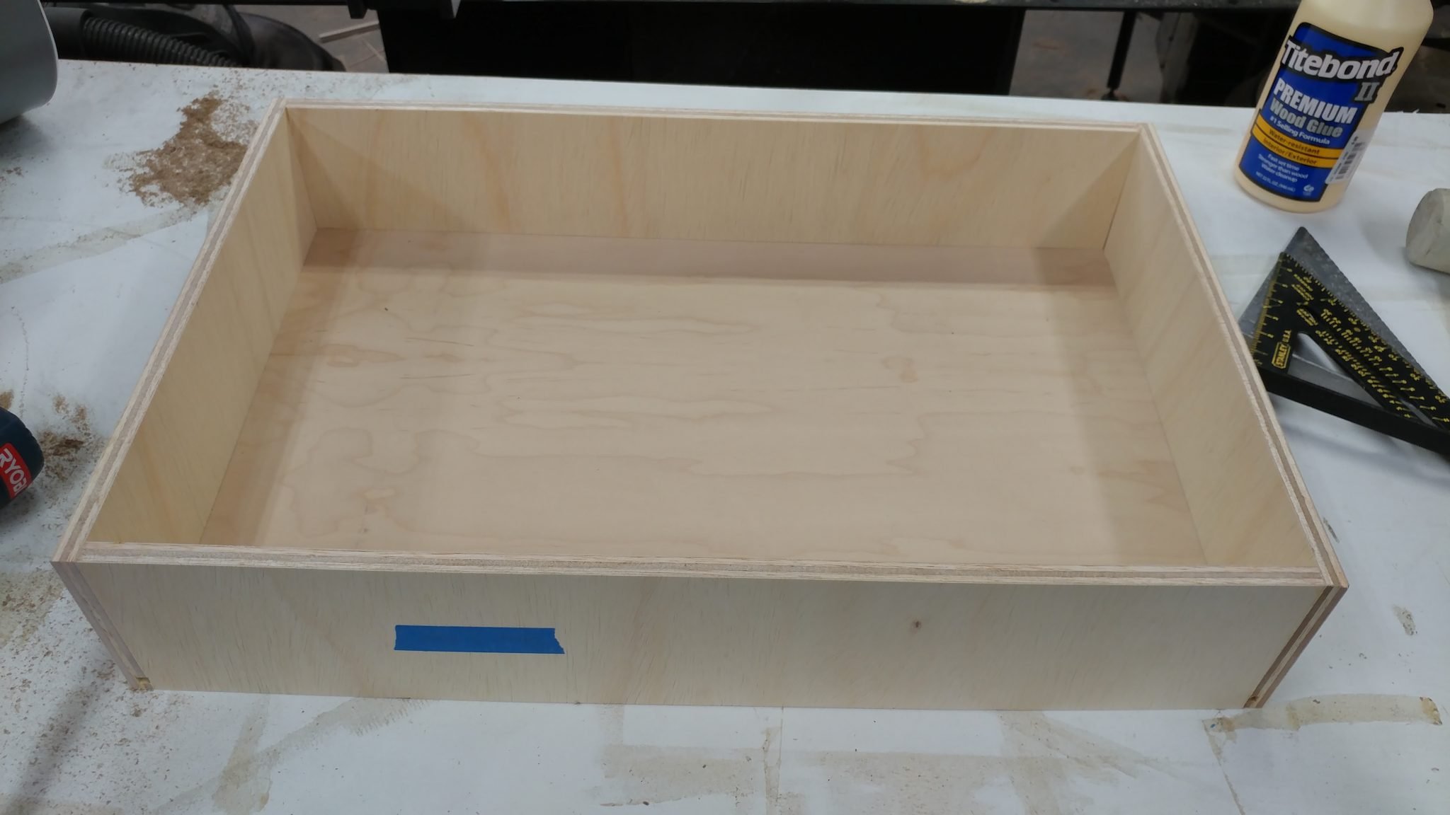
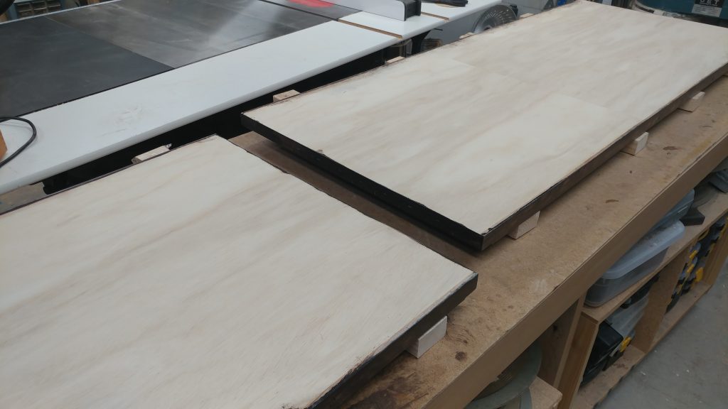
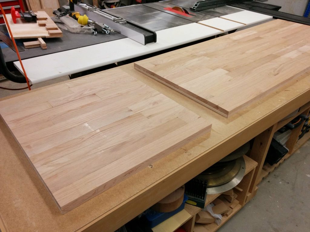
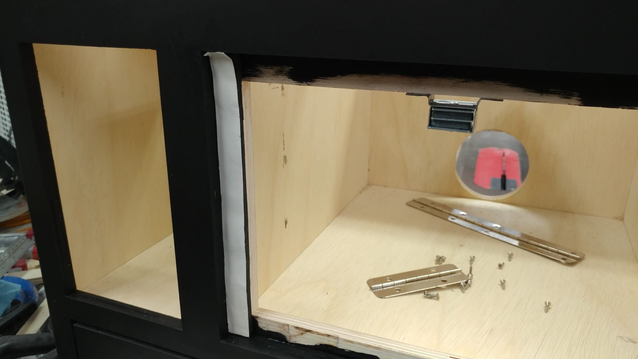
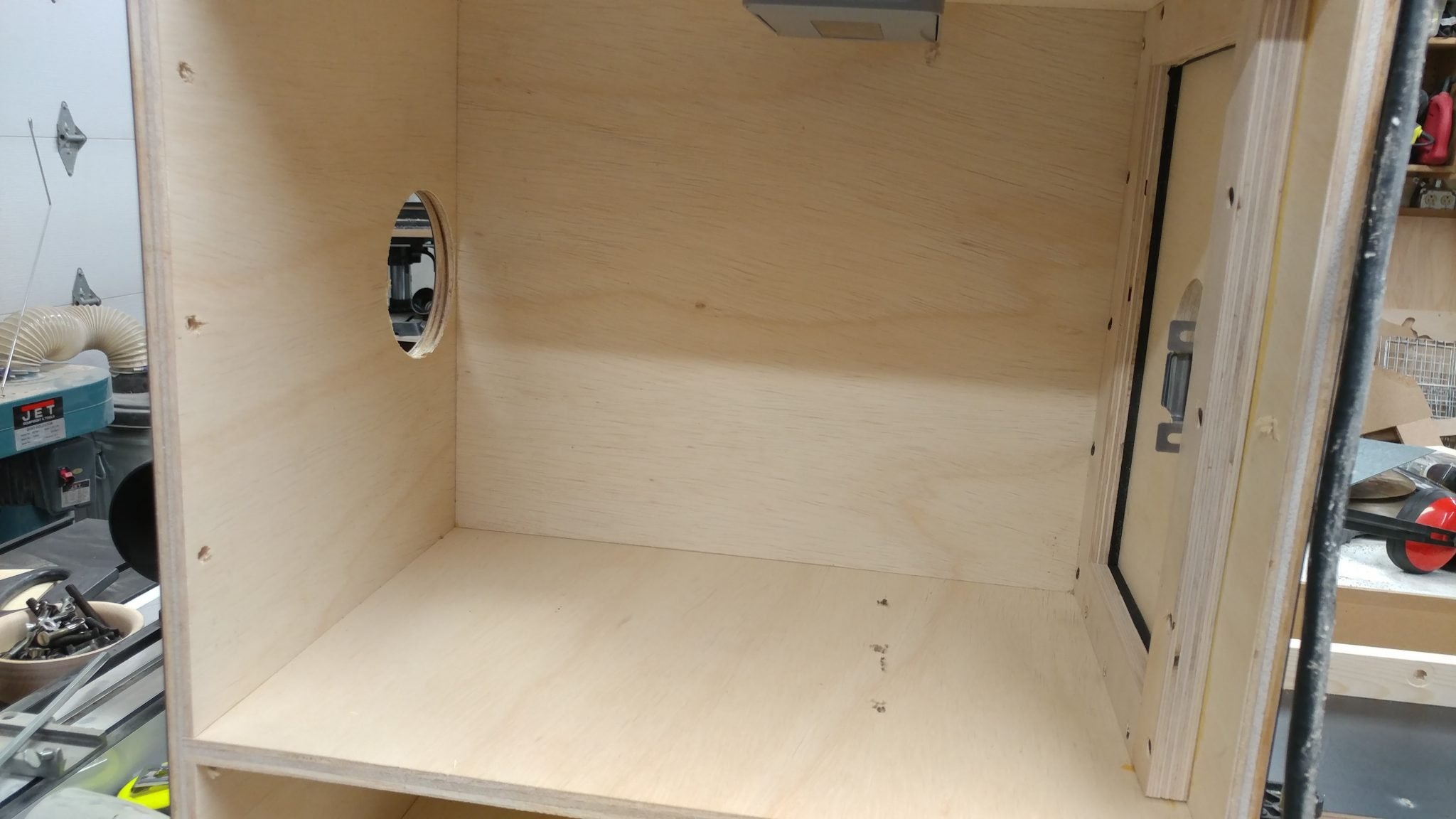
The main carcase is assembled and ready for the hardware.
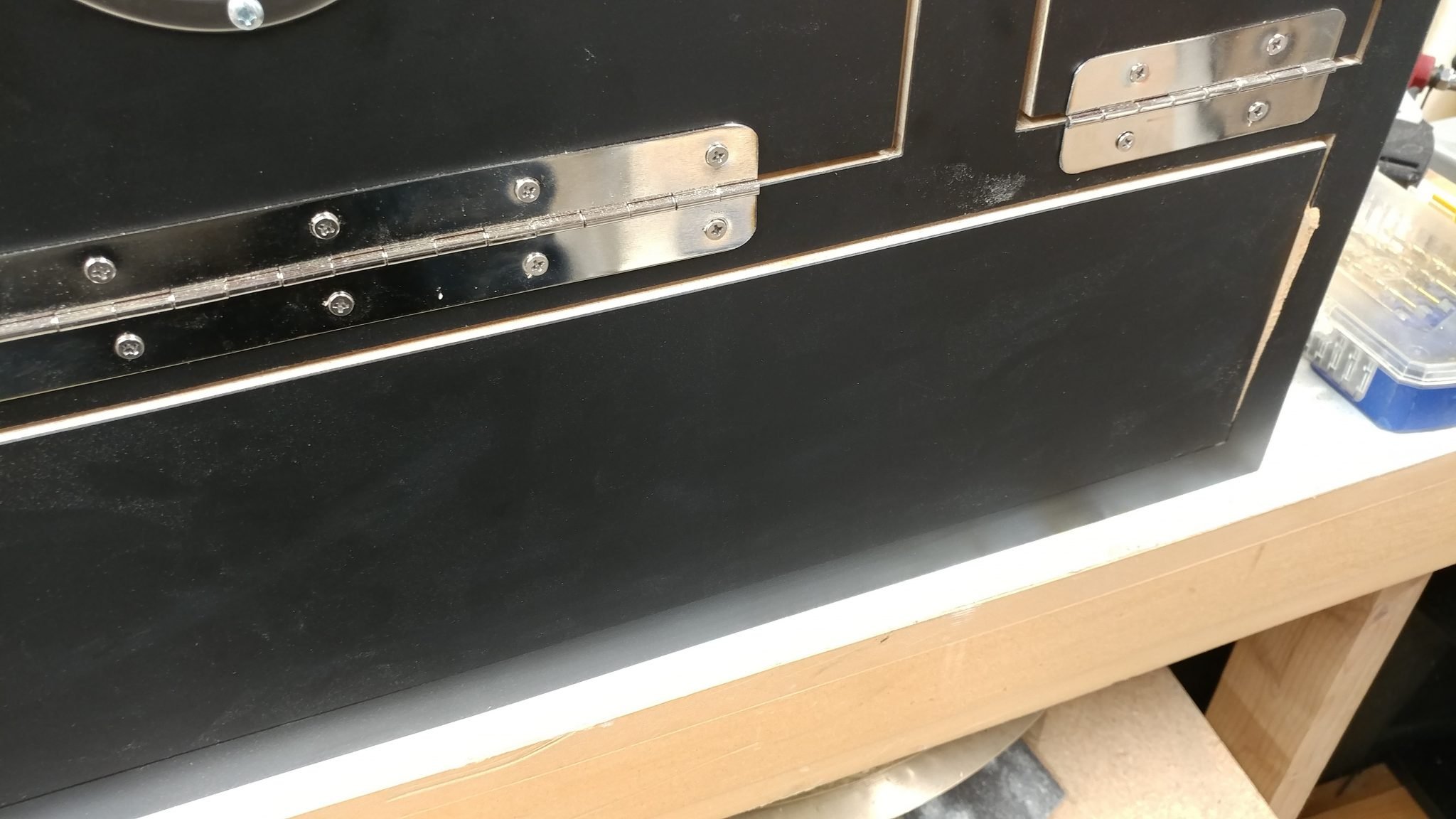
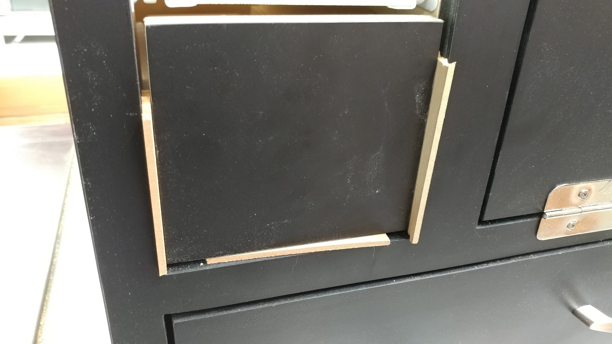
To start with, I attach the main door. I use some 1/8″ thick MDF pieces as spacers on each edge of the door.

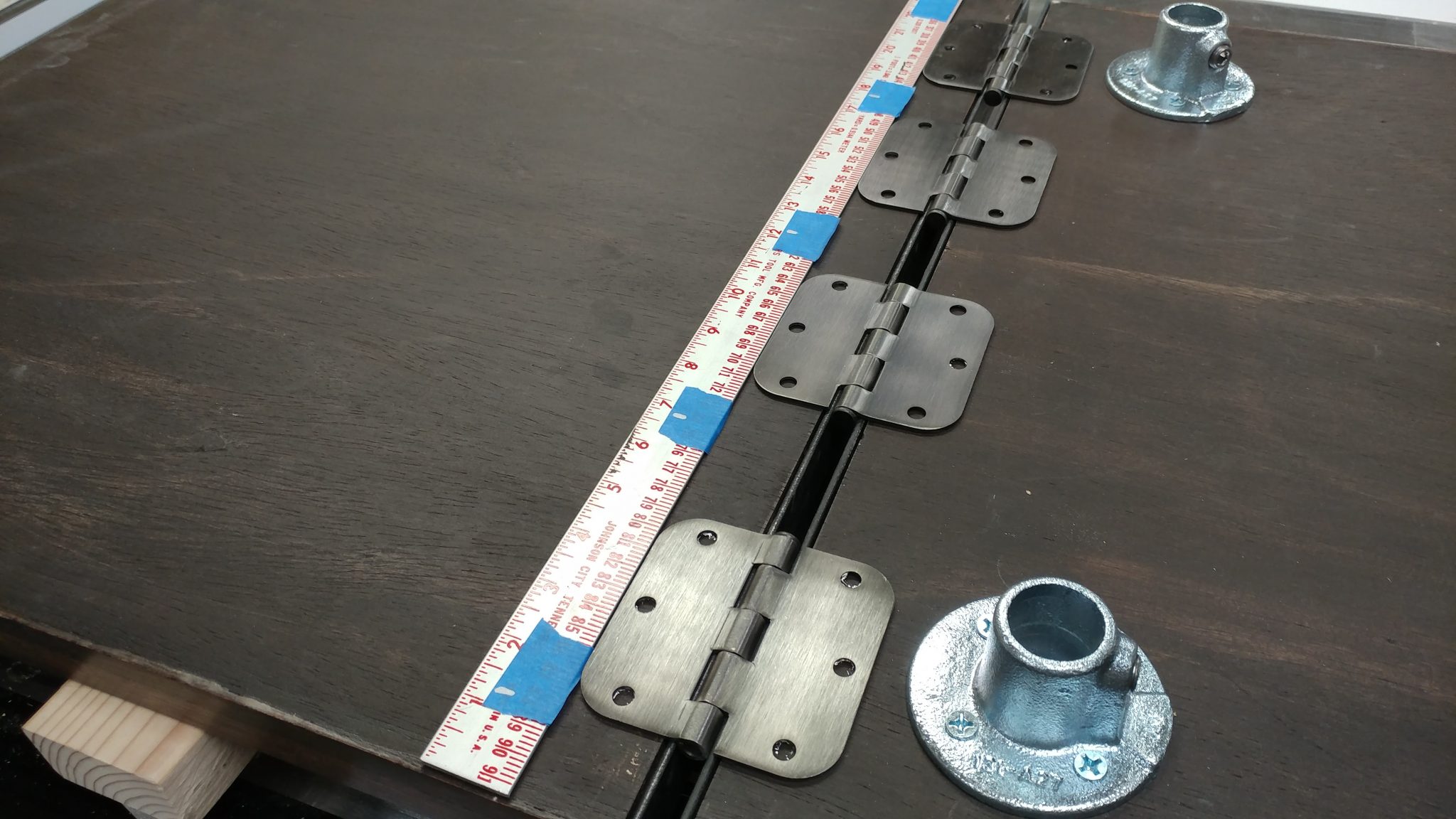
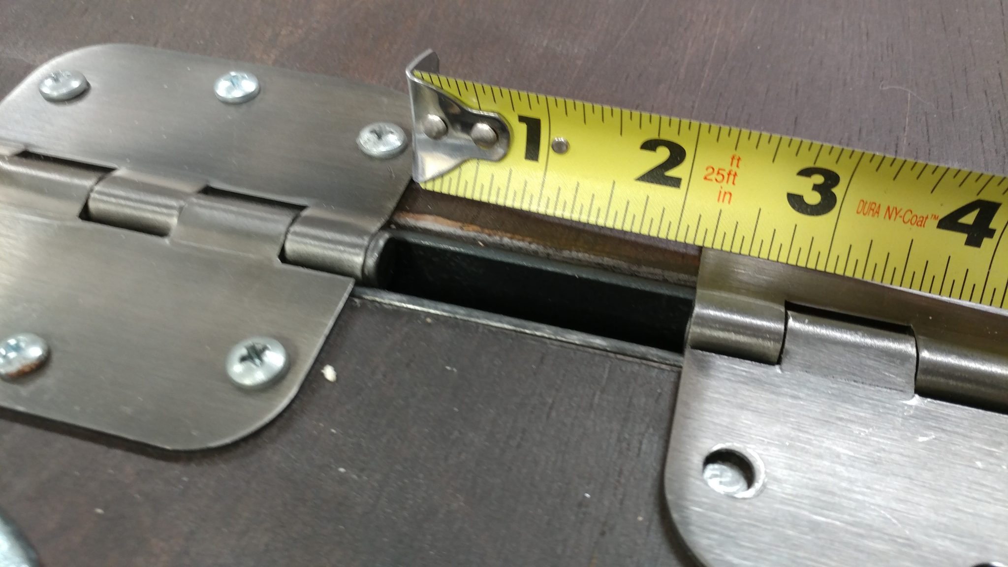
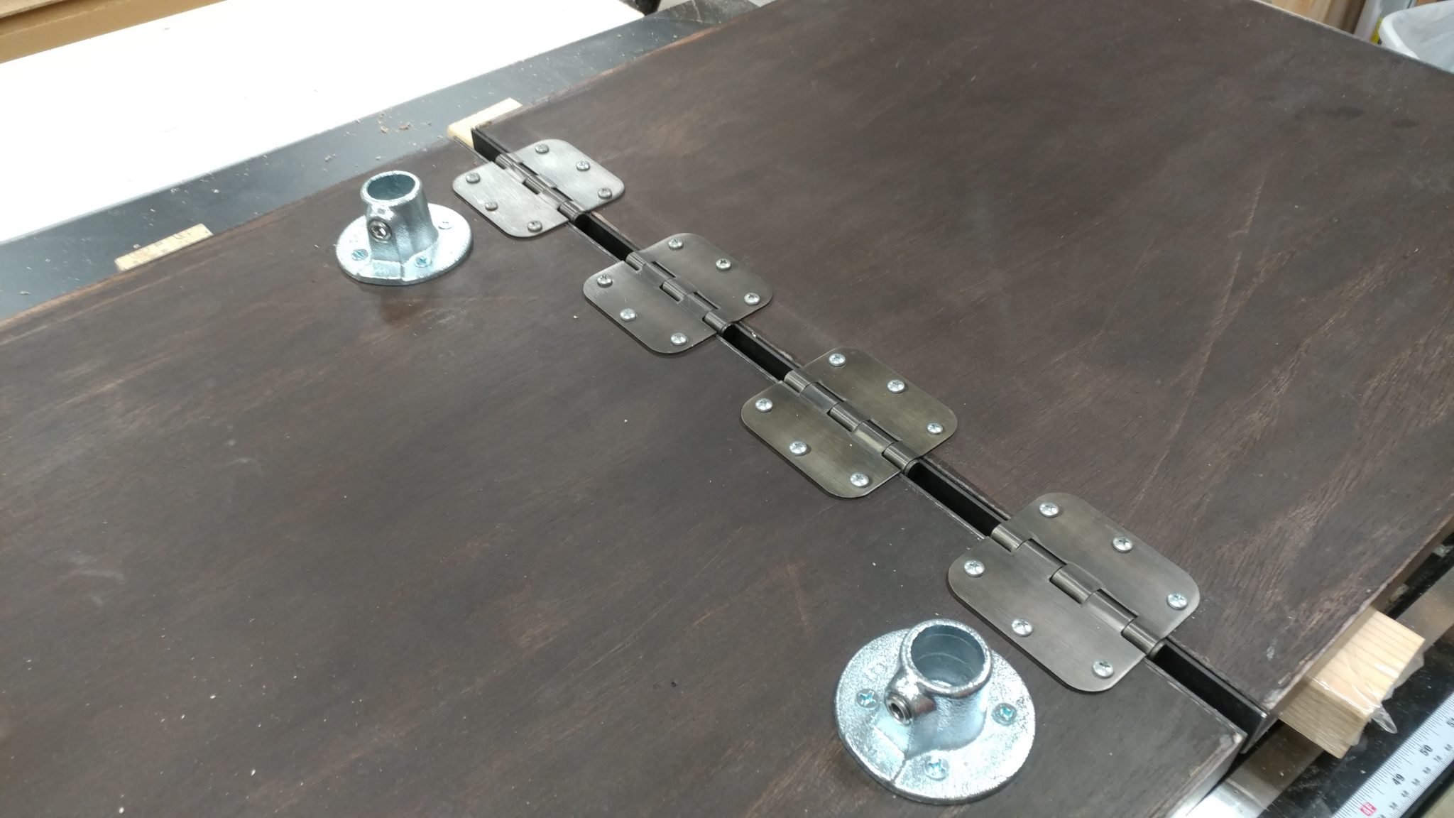
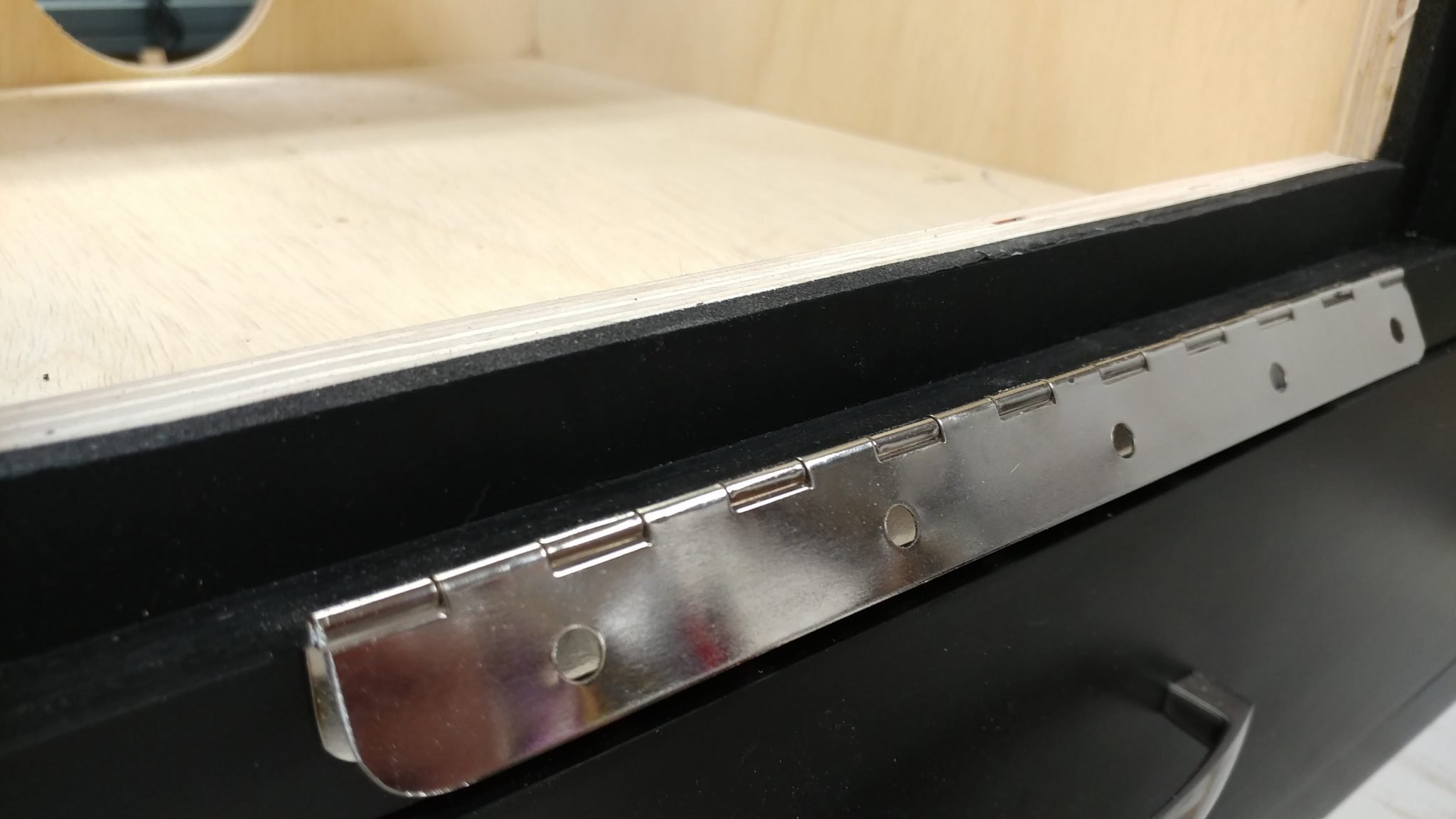
With the spacers holding the door in position, I attach a piano hinge.
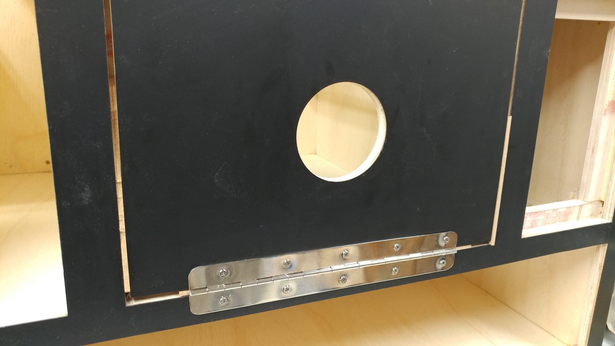
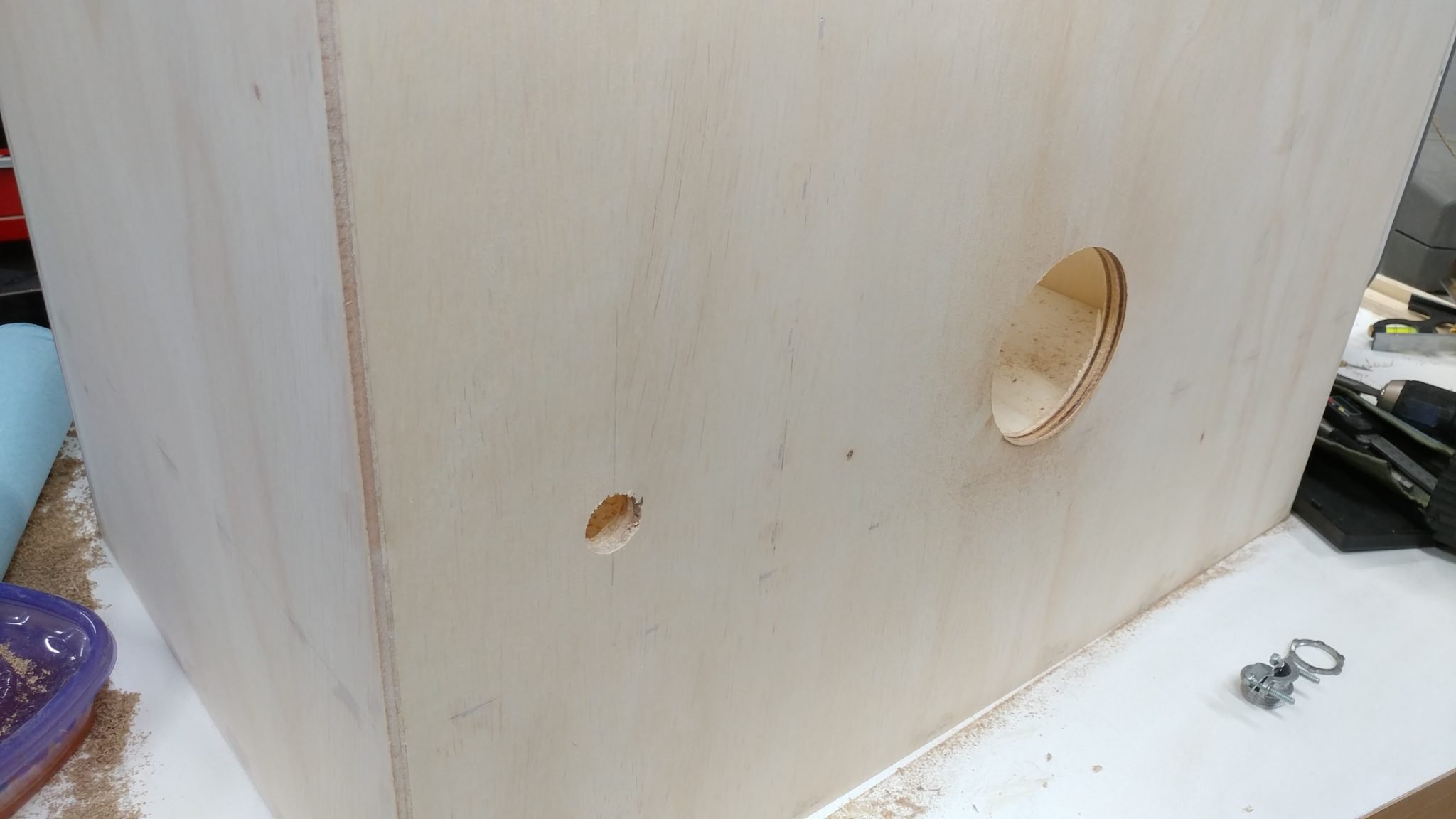
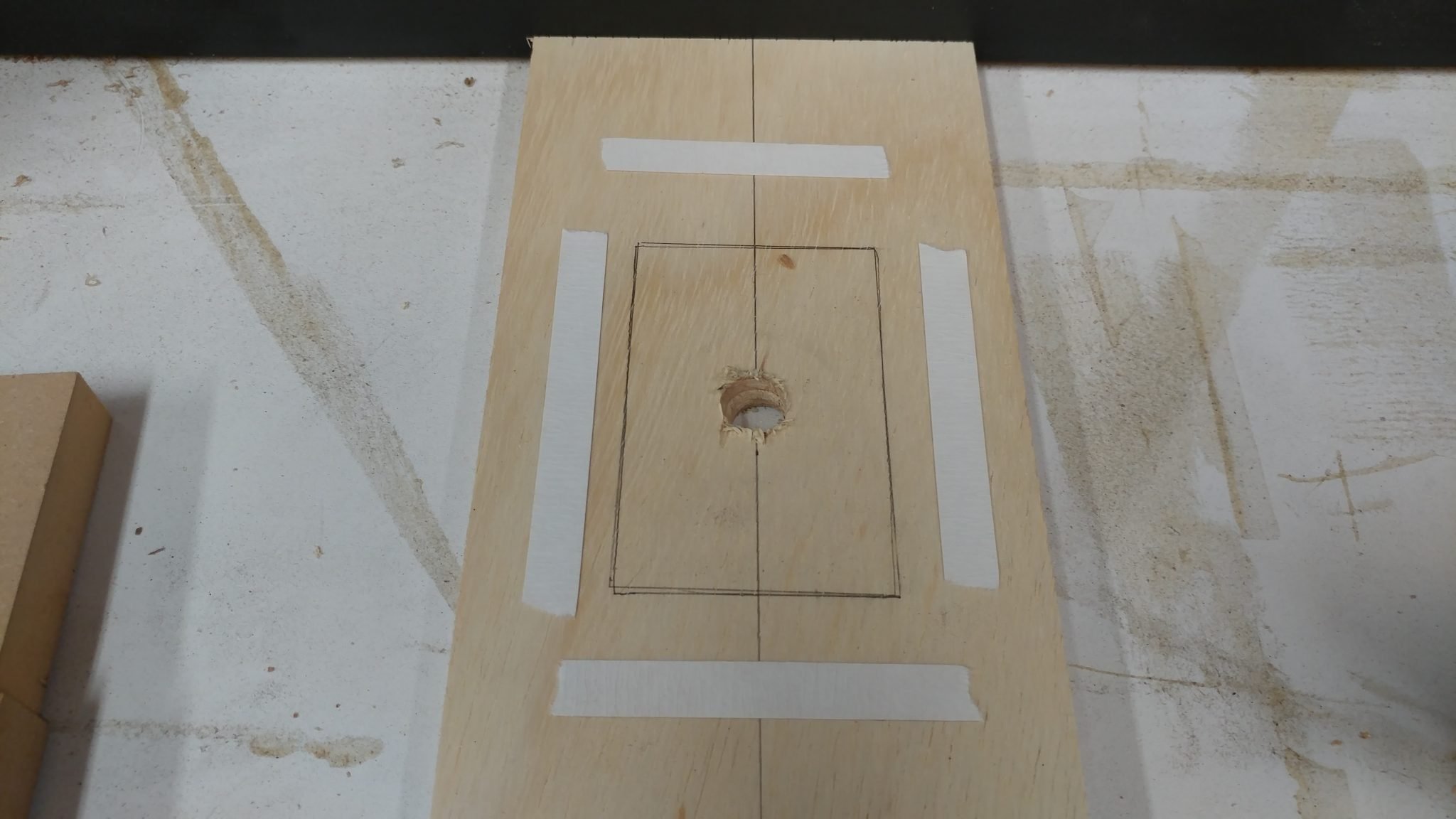
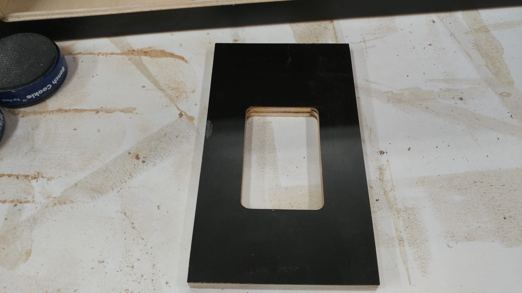
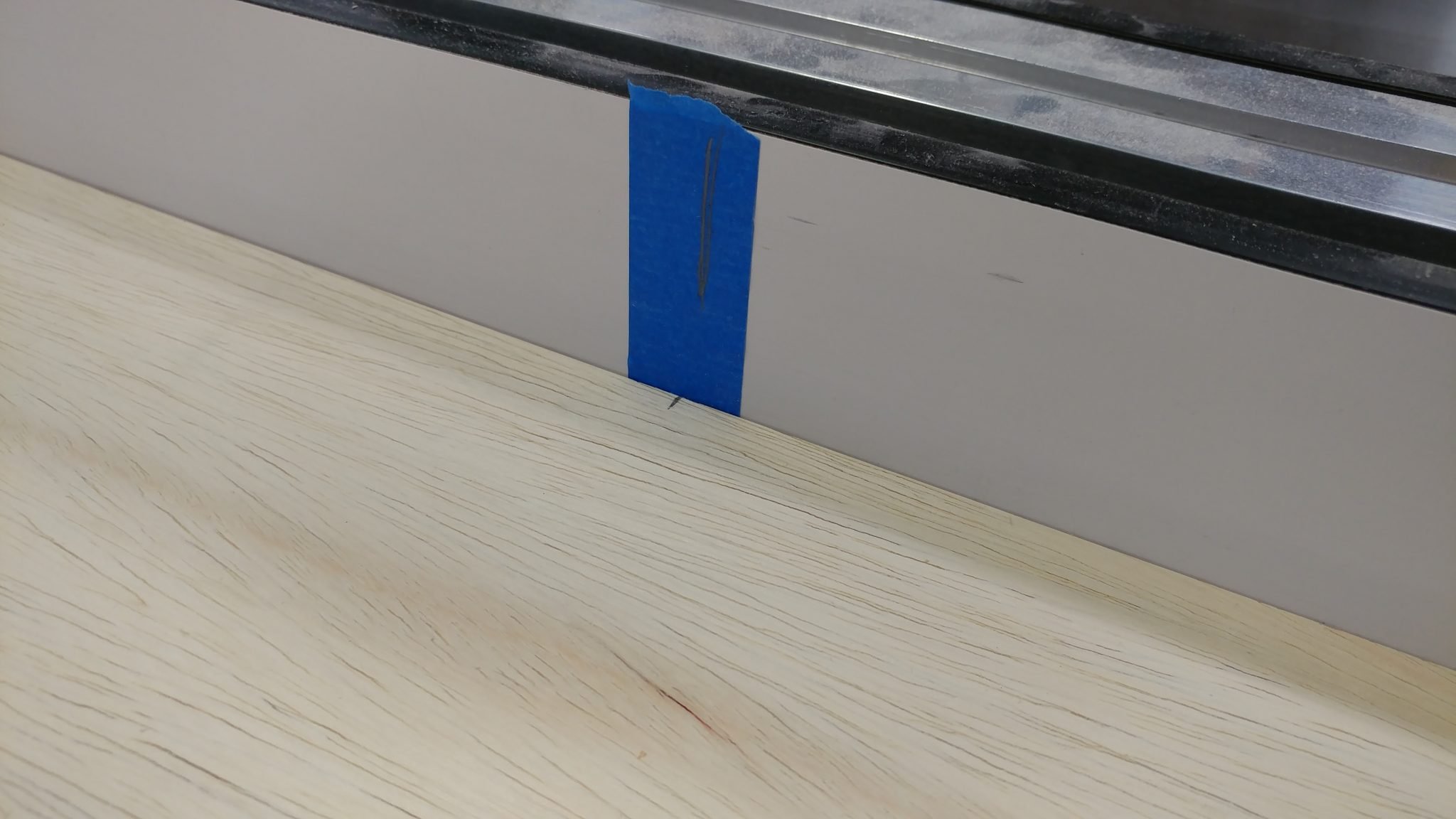
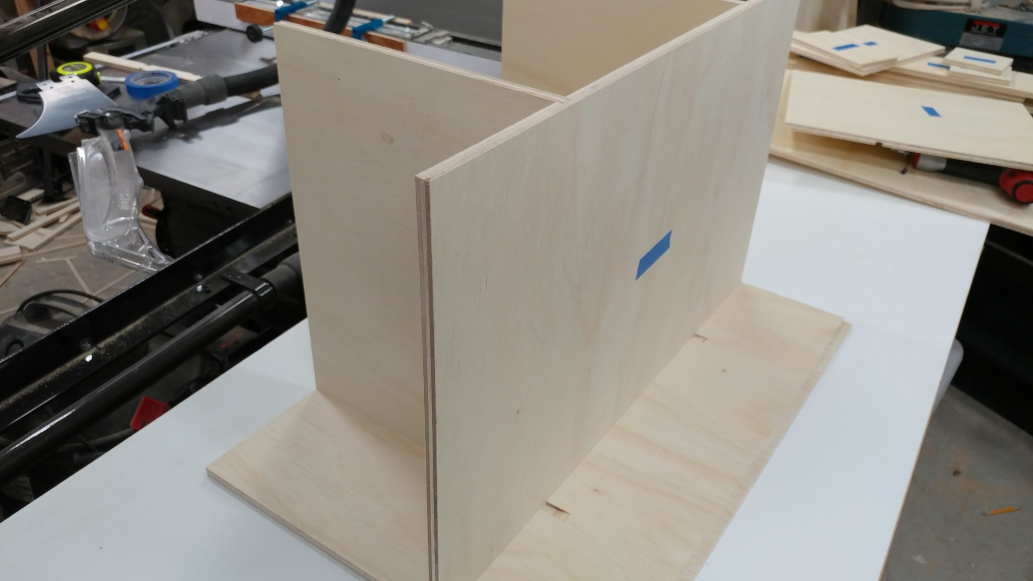
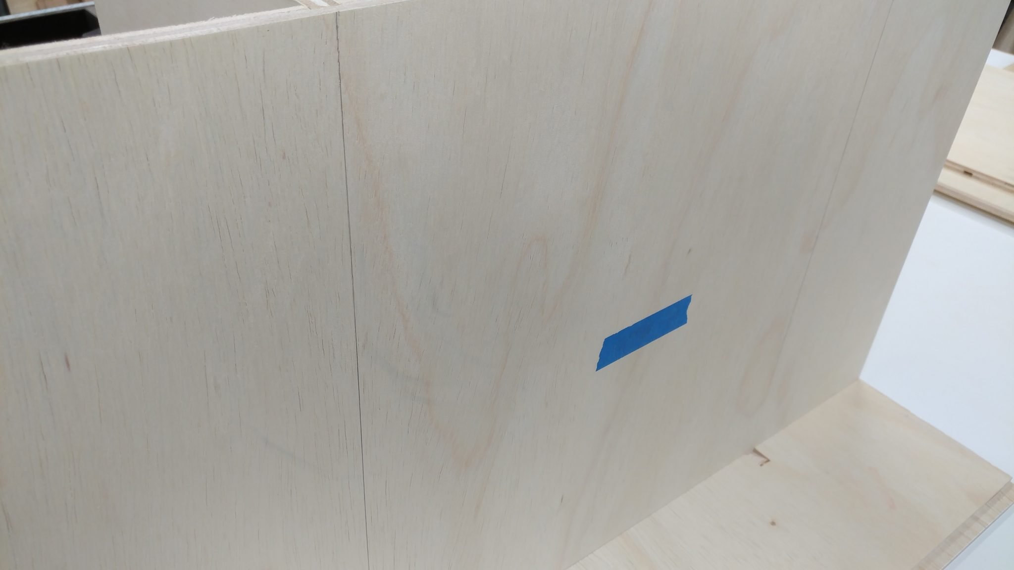
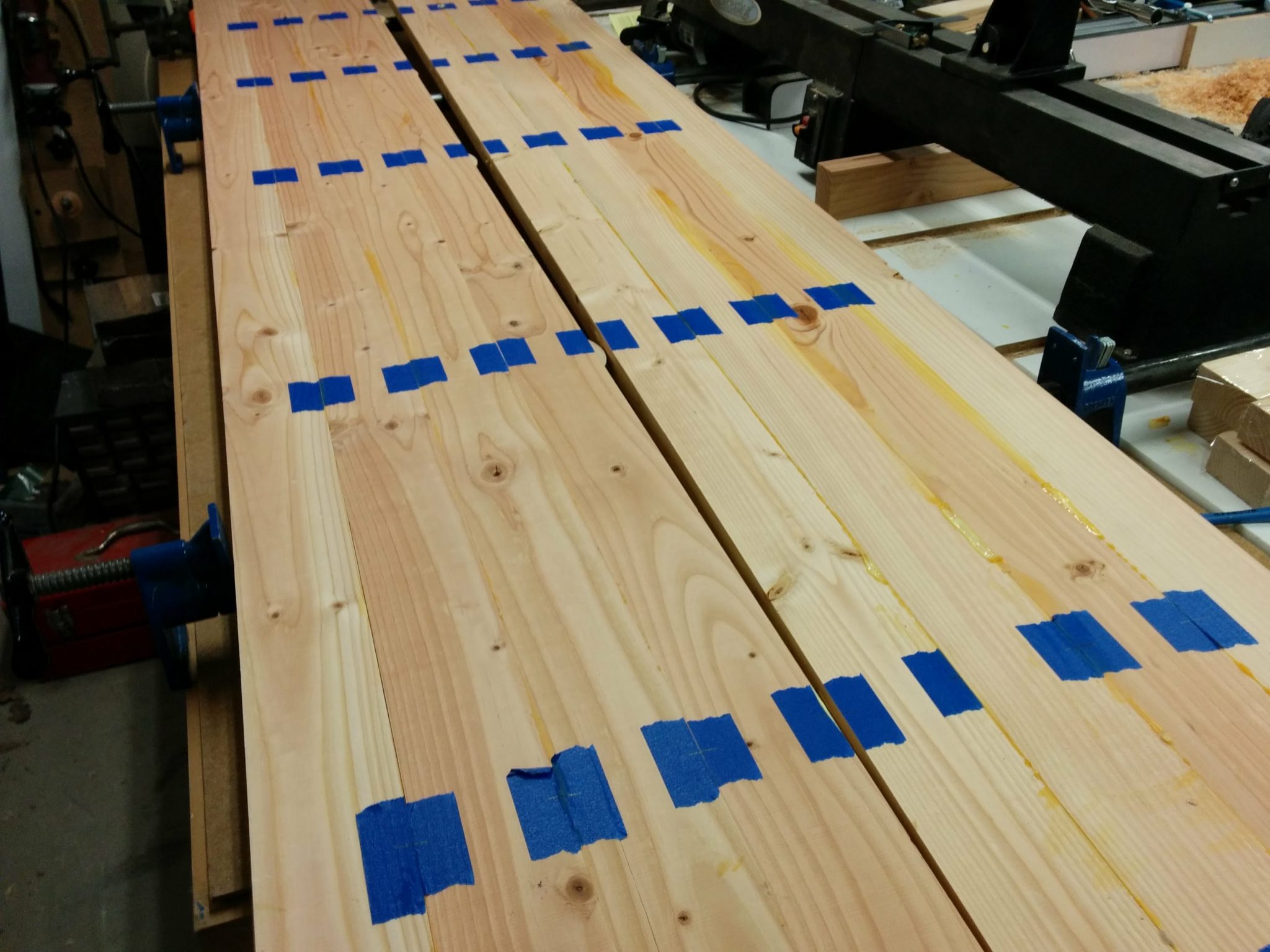
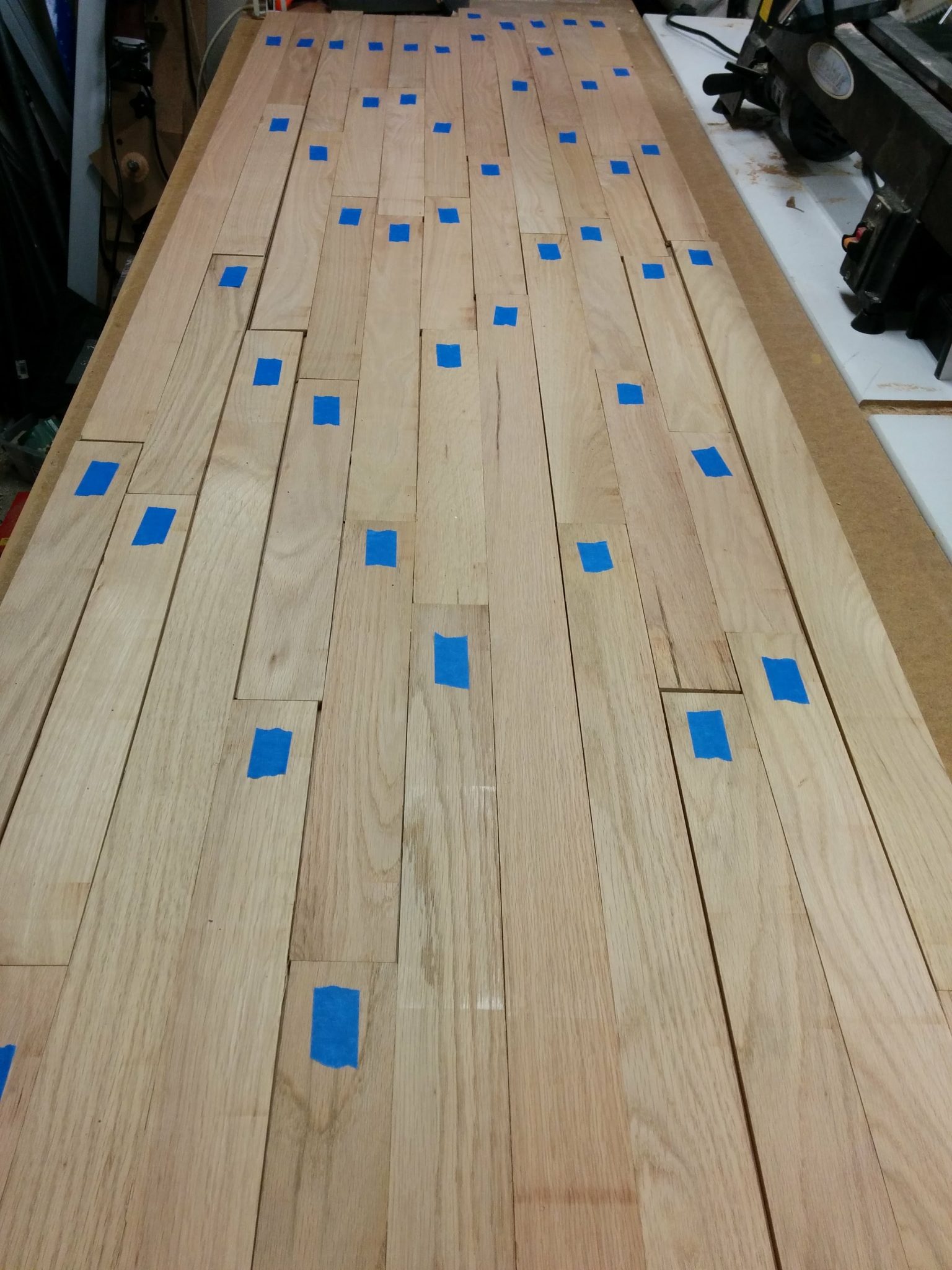
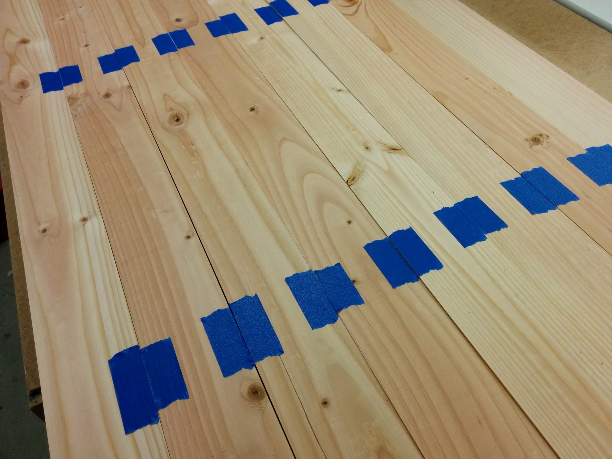
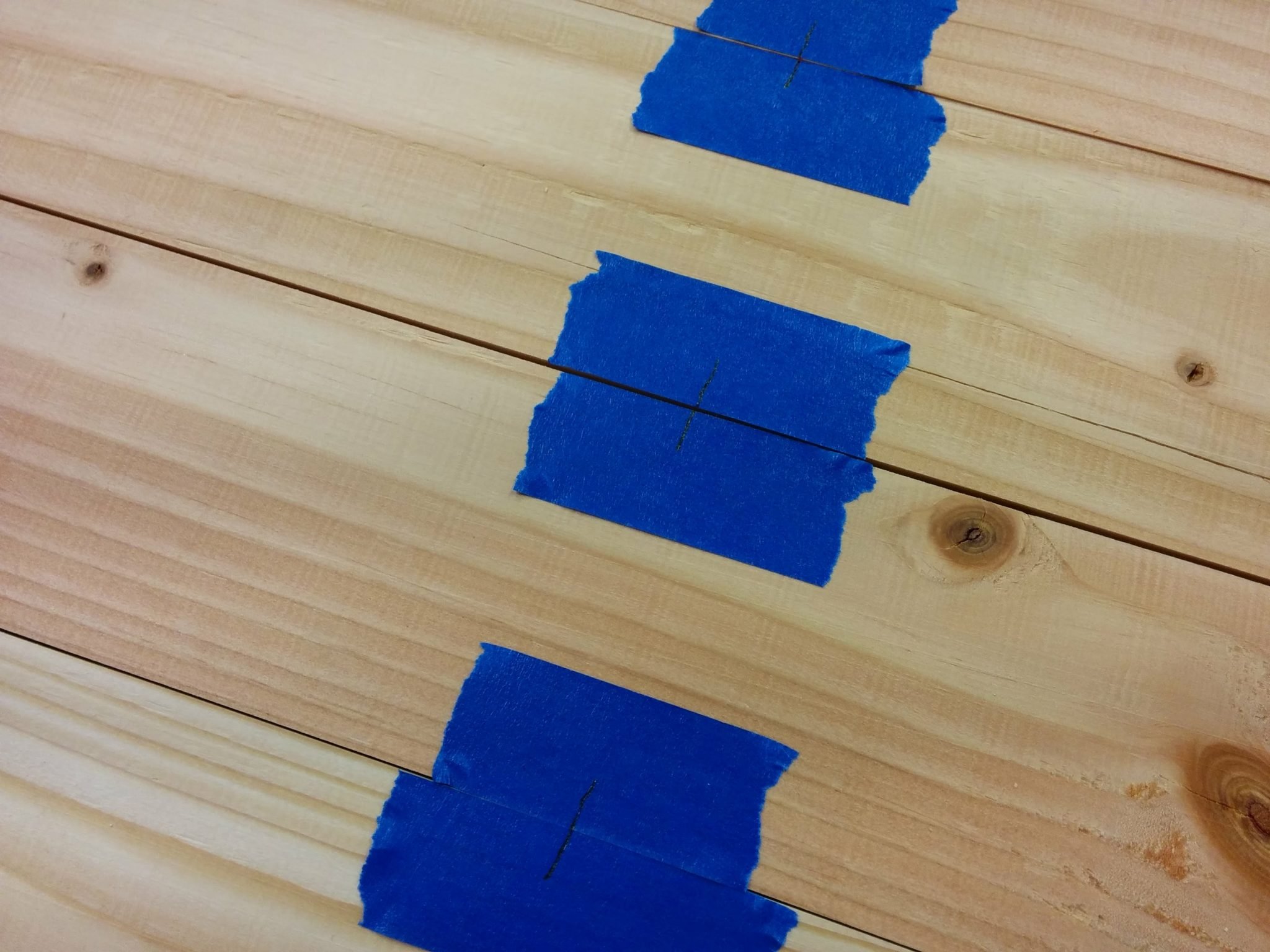
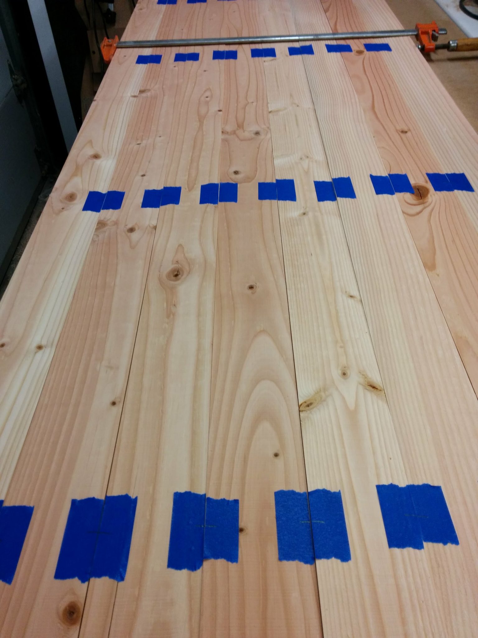
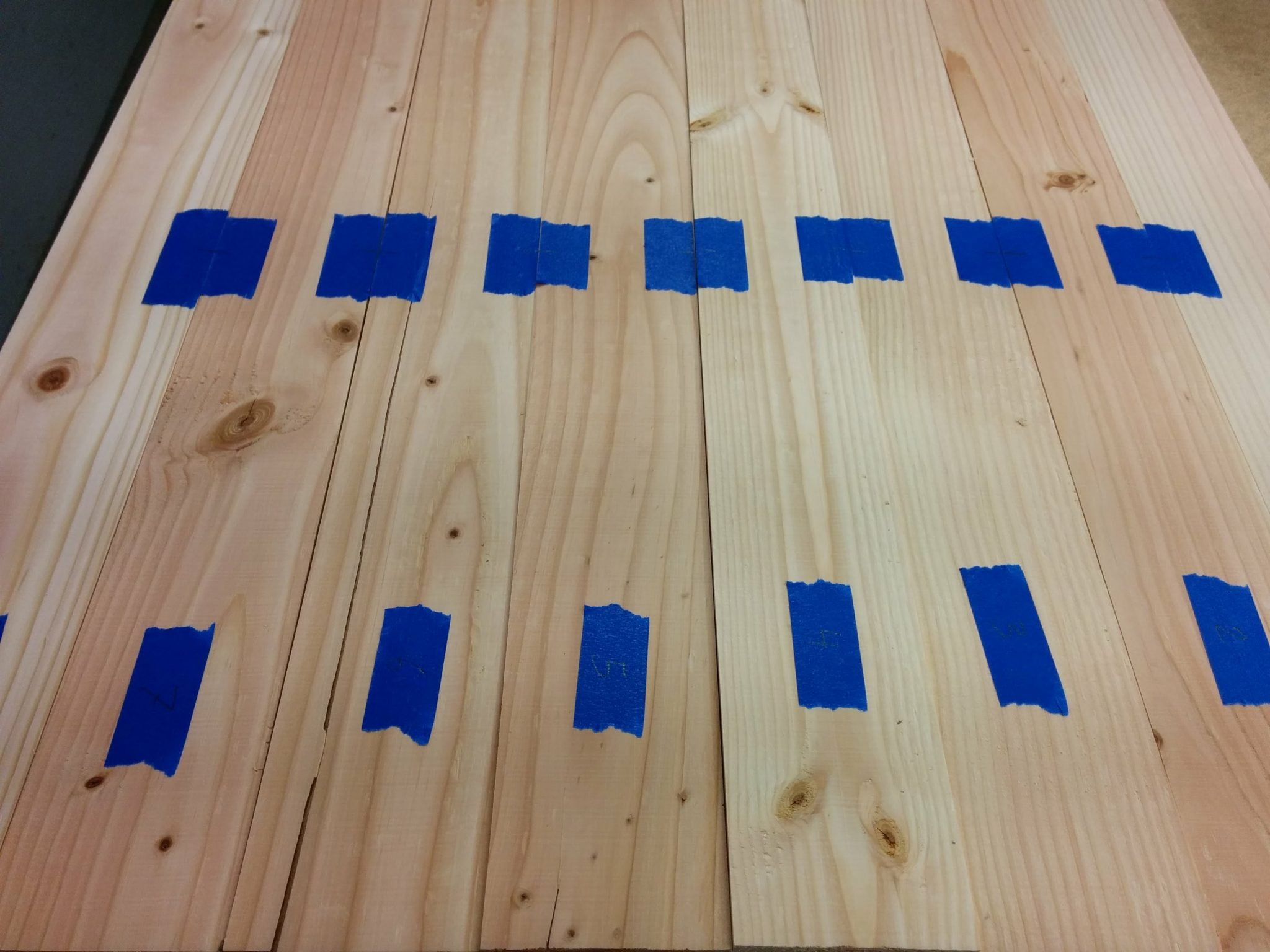
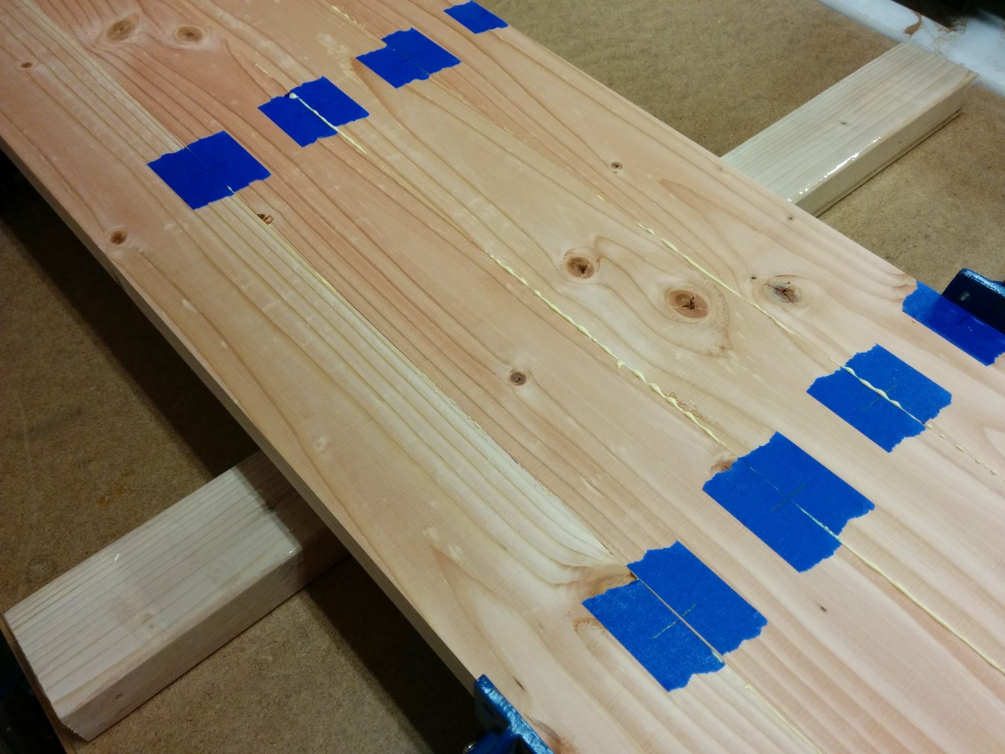
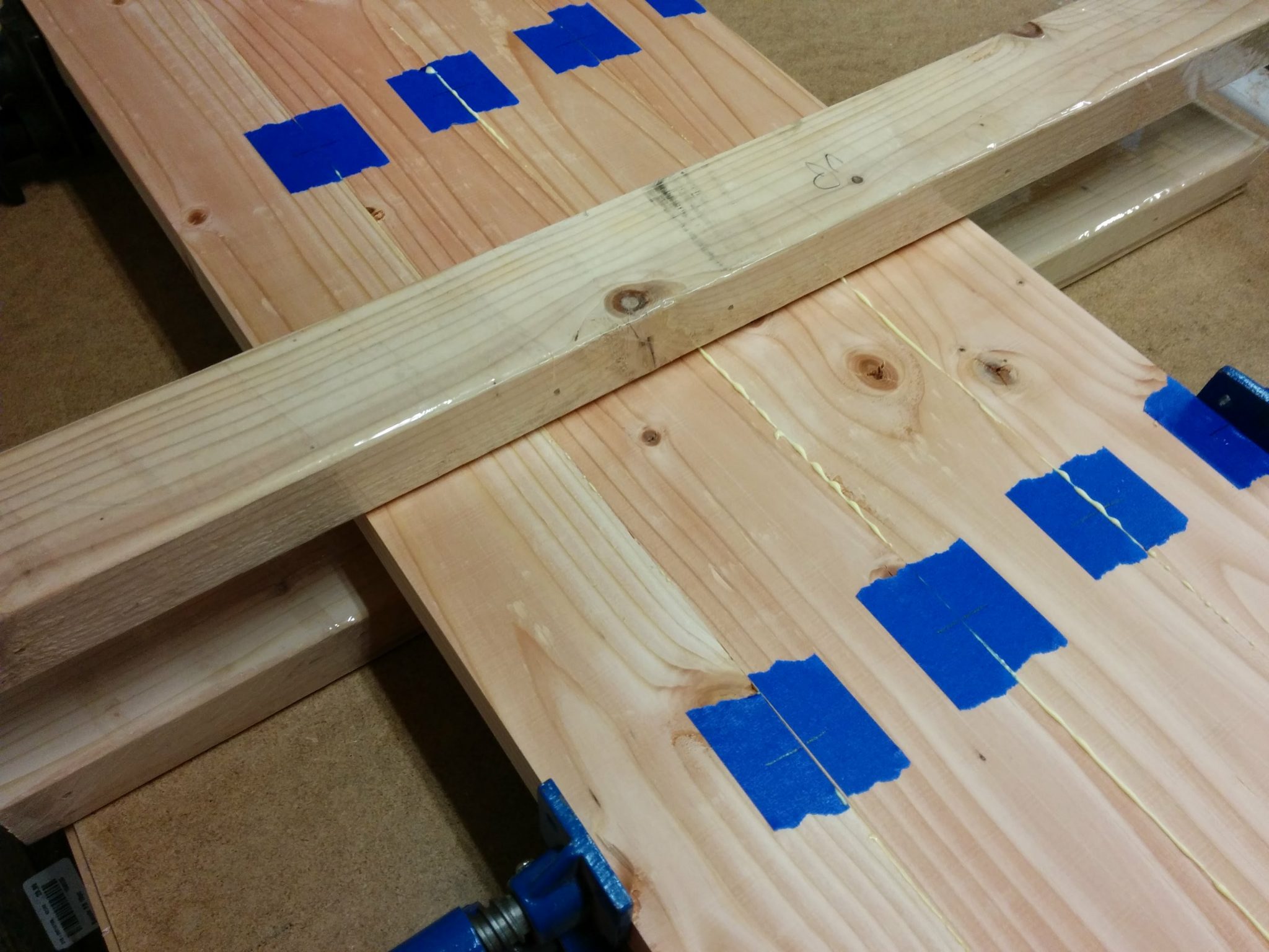
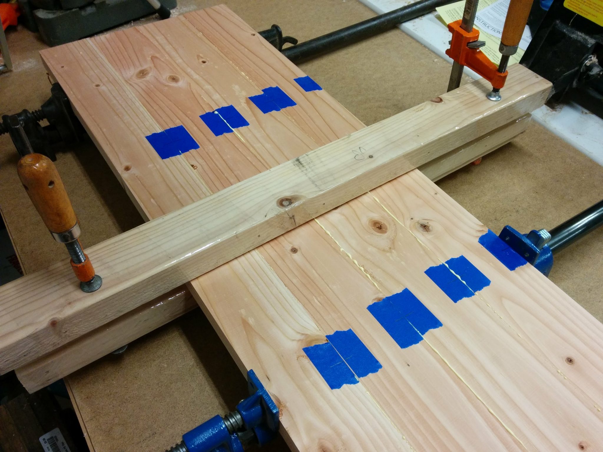
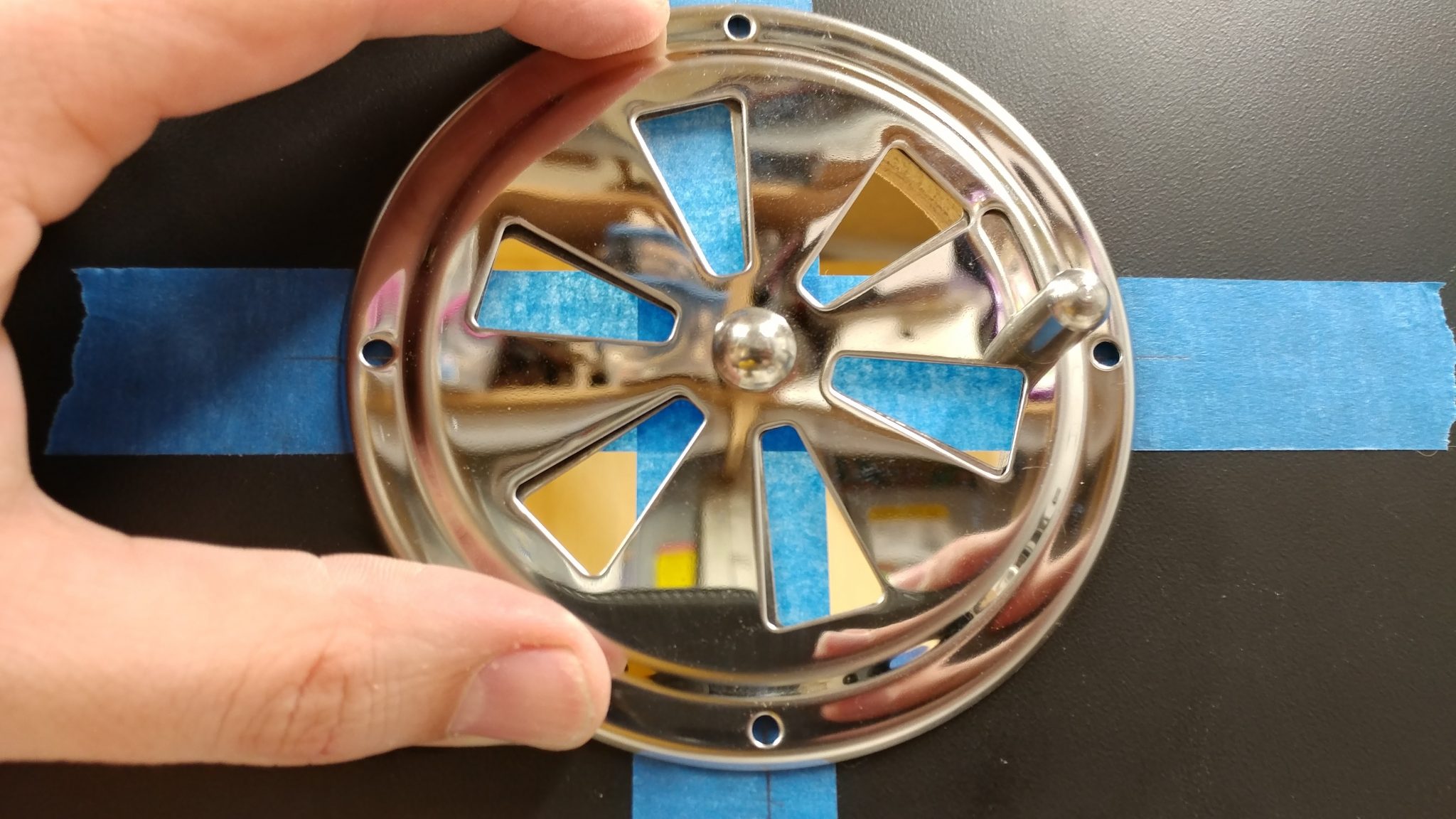
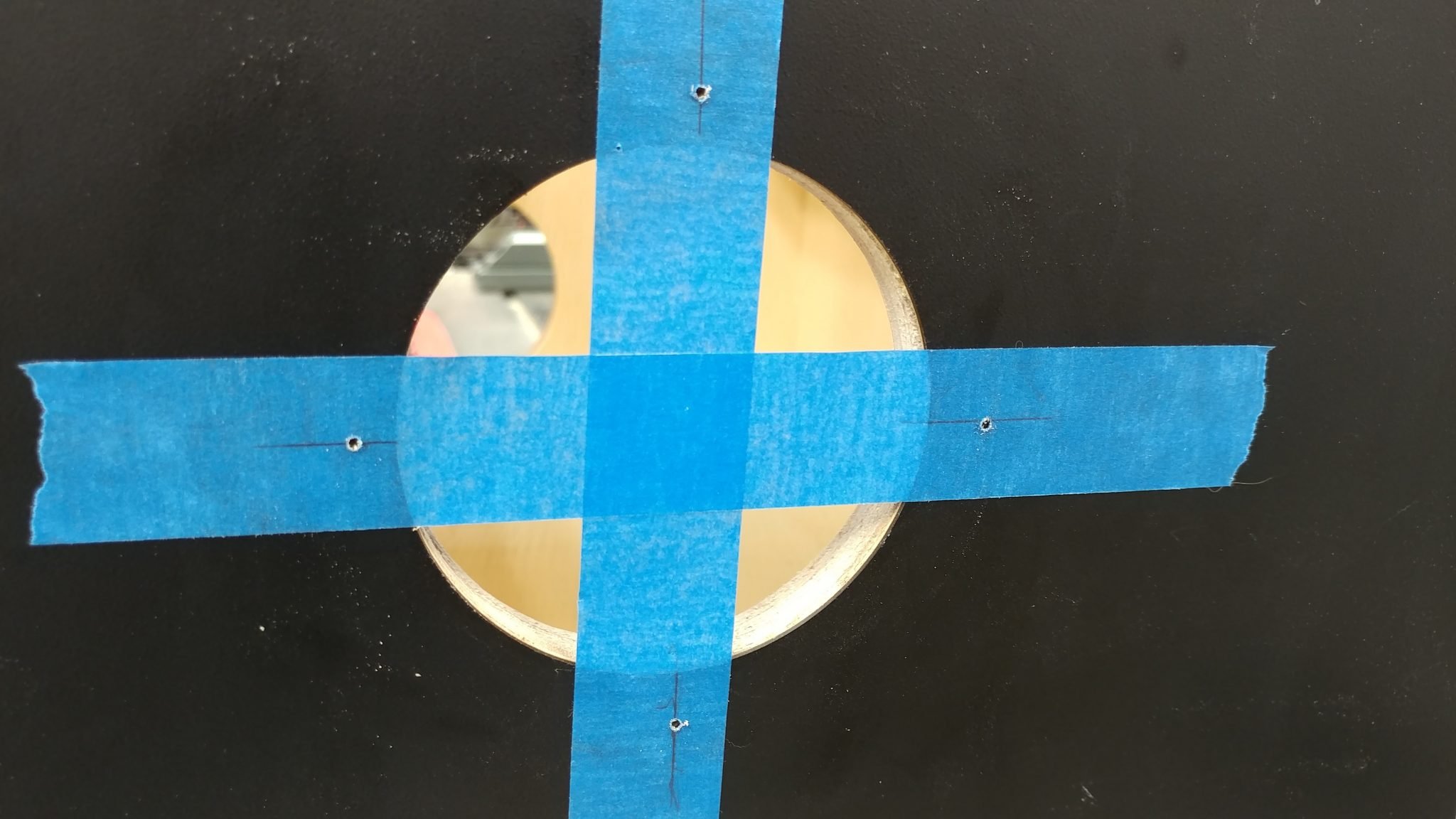
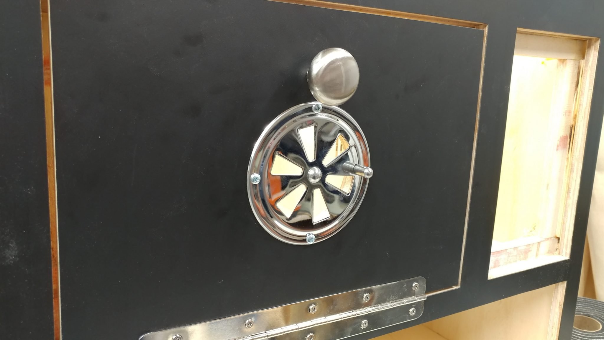
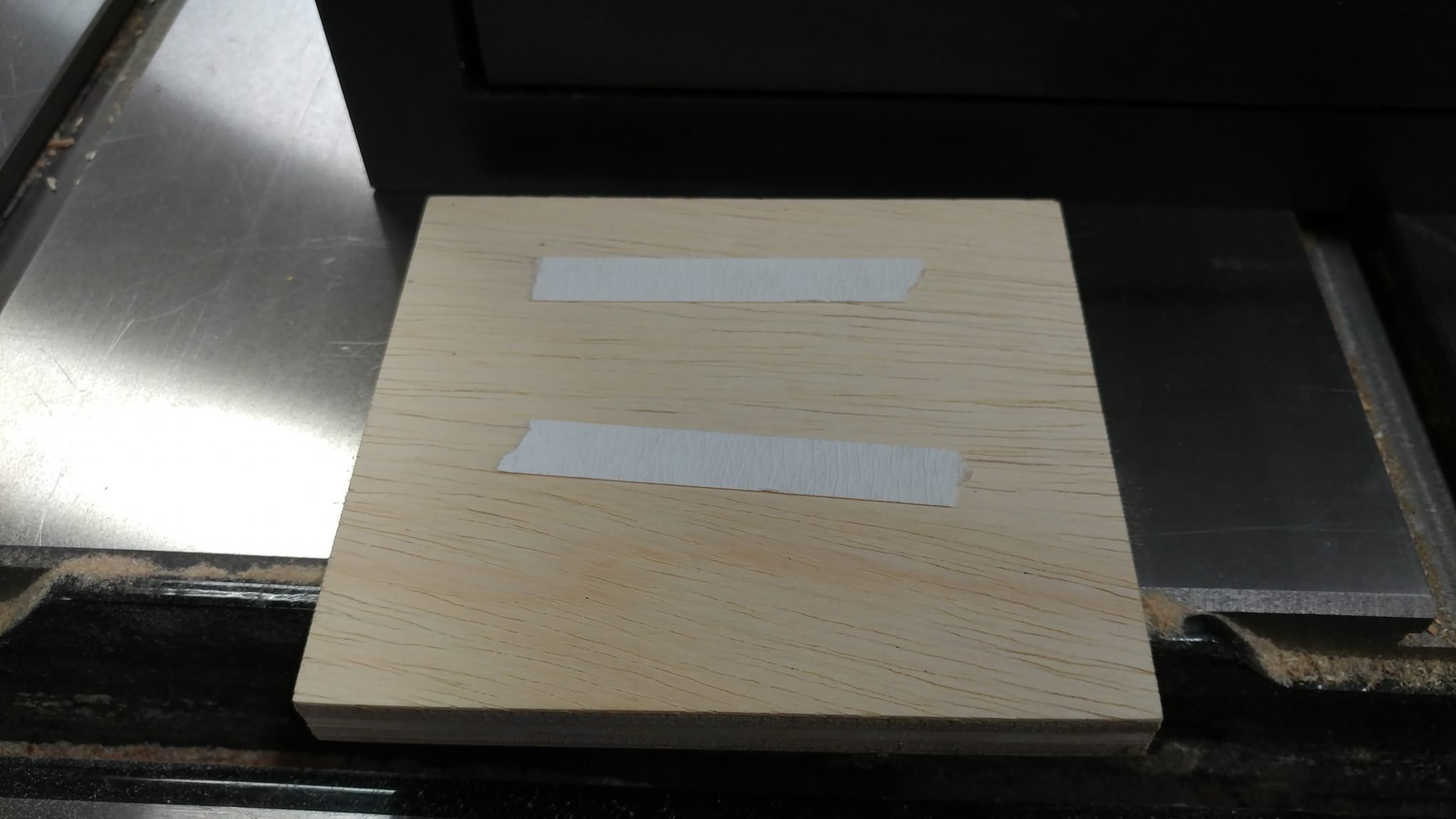
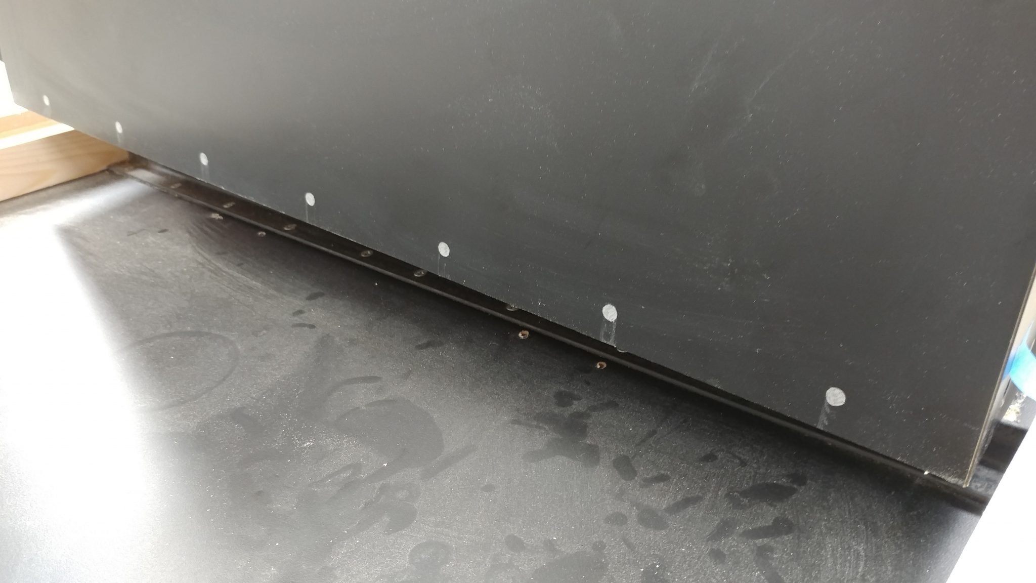
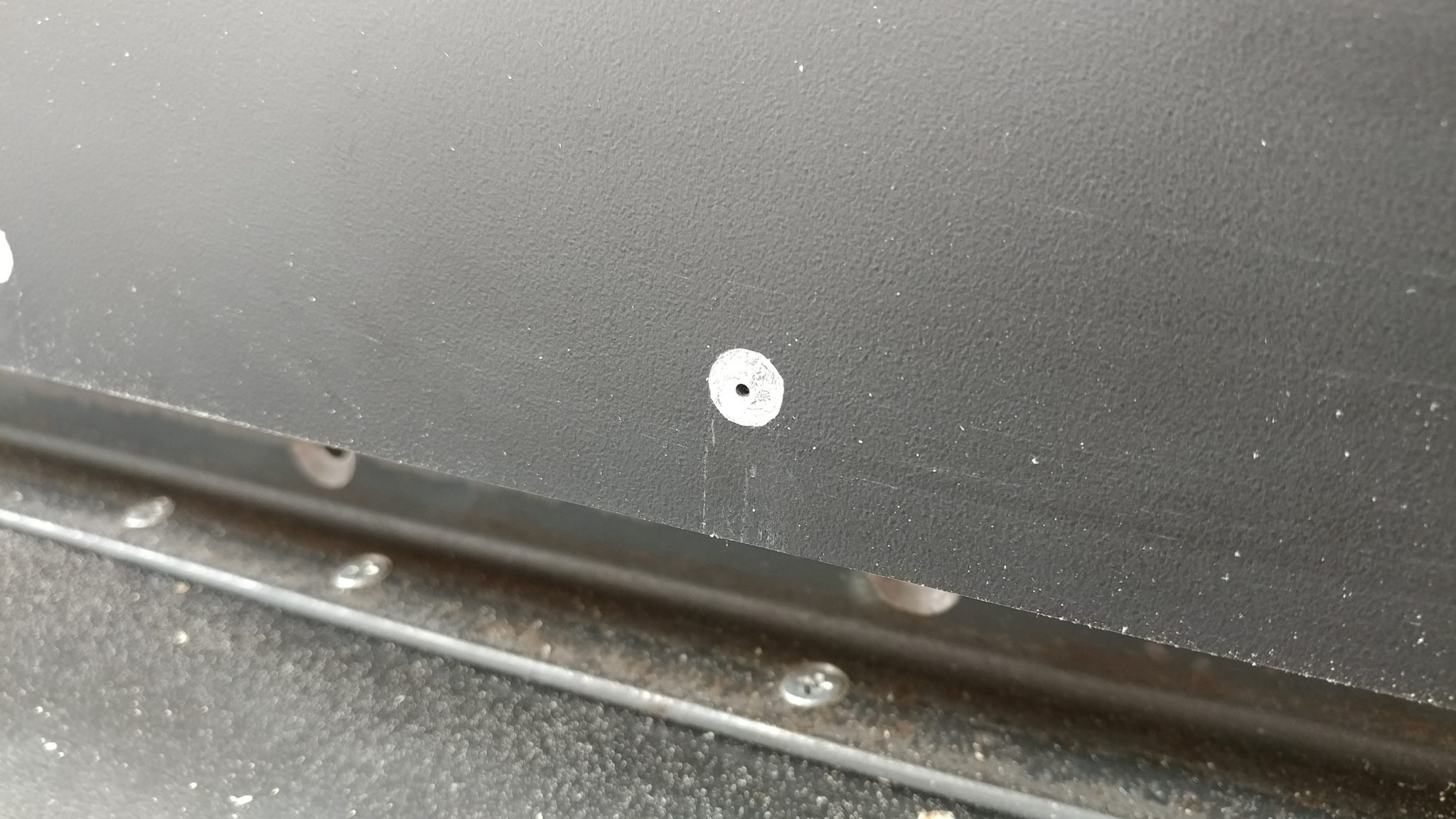
To position the air vent, I put some blue painters tape across the opening and mark the center lines where the screw holes on the vent should line up.
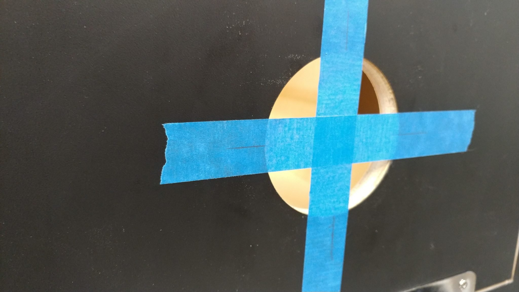
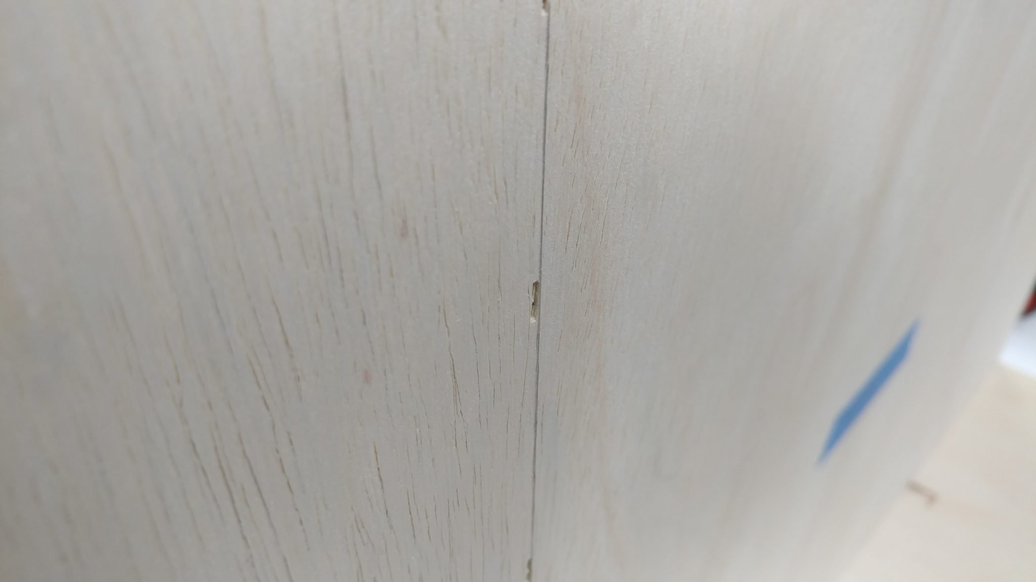
I then position the air vent with the lines going through the center of the screw holes…
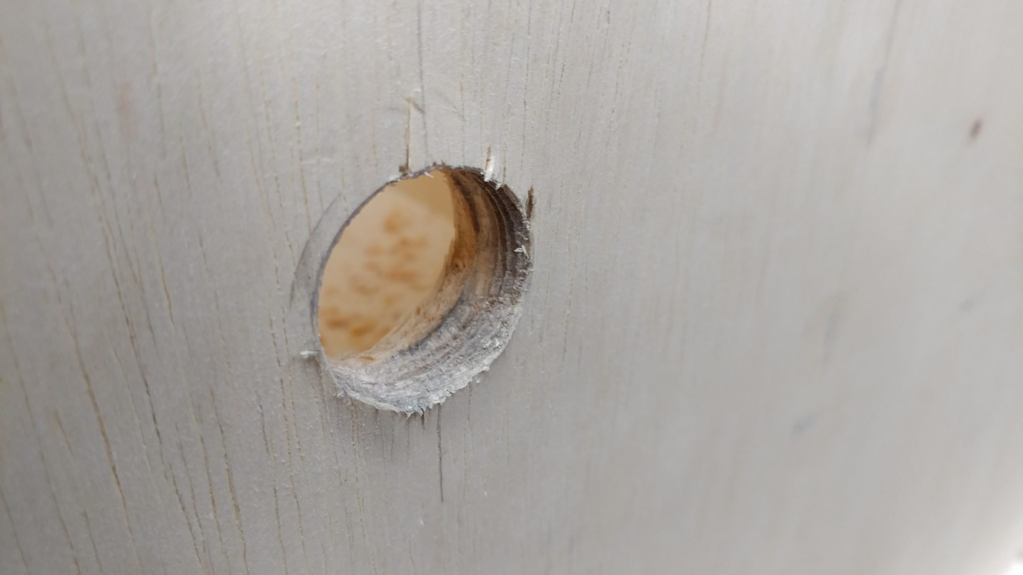
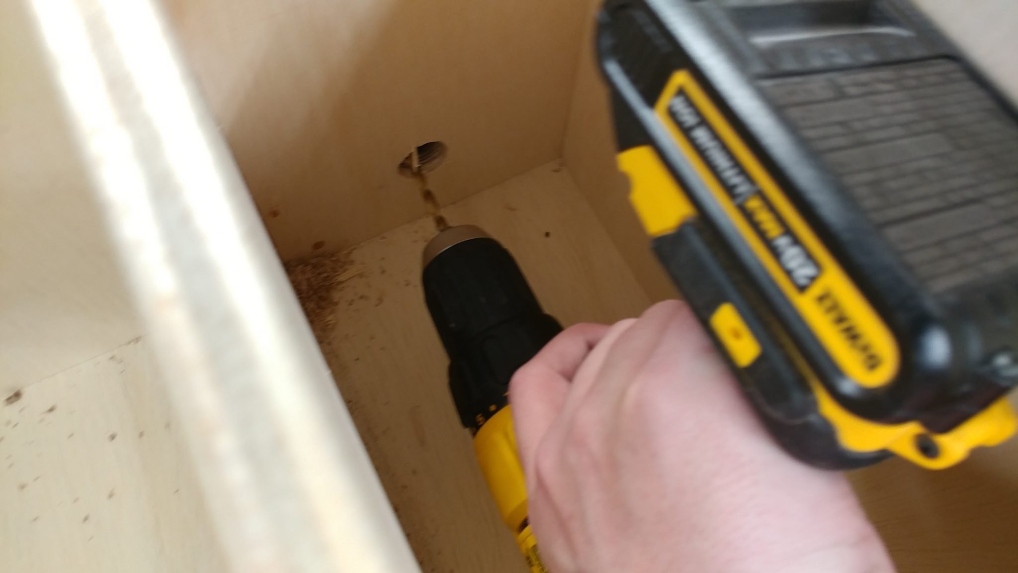
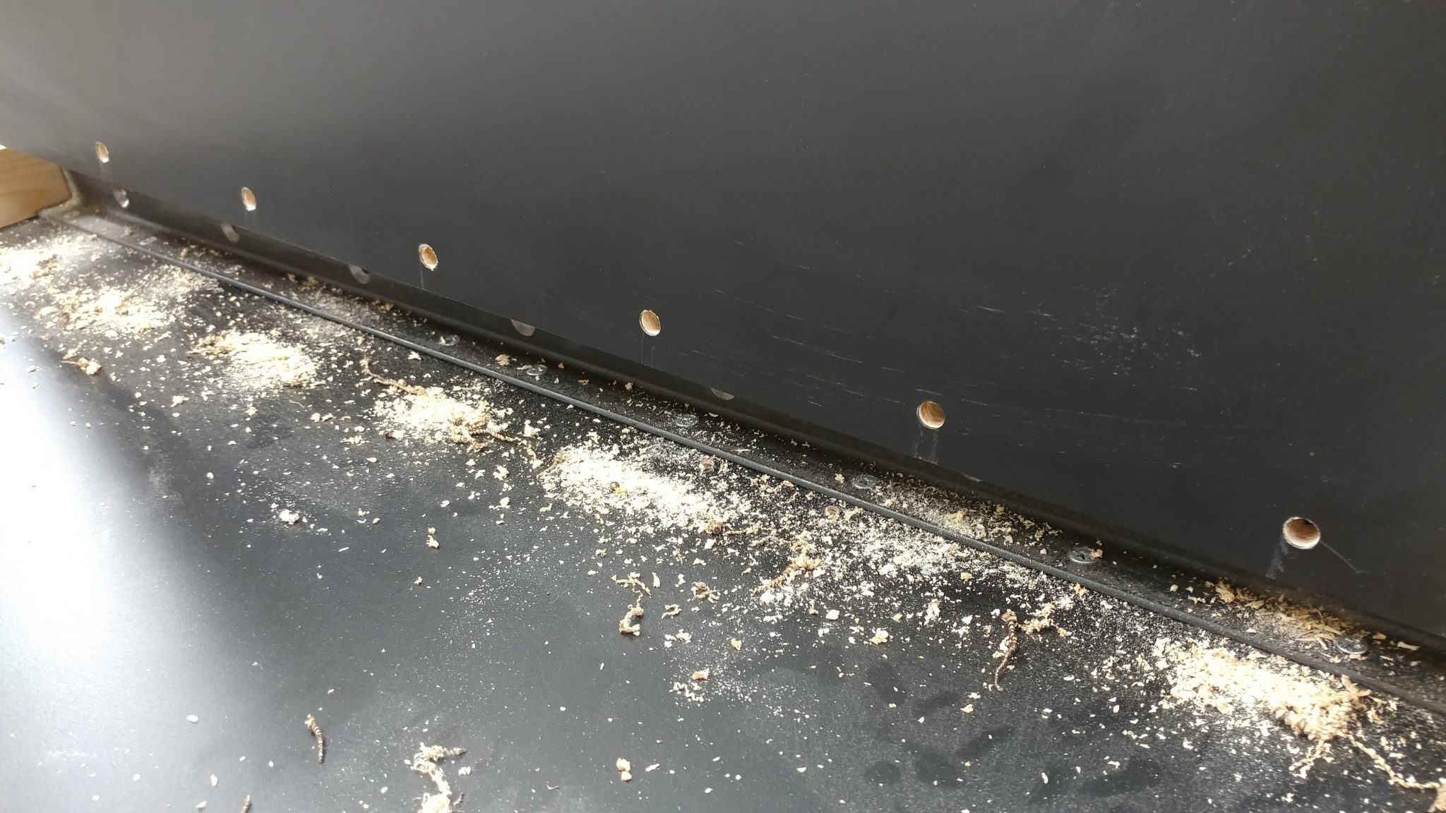
…and drill pilot holes for the screws.
I then installed a magnetic door catch to hold the door closed.
I can then close the door. The 1/8″ spacers made a nice gap.
On the inside of the door, I drill a hole as close to the metal plate of the door catch as I can so I can attach a handle.
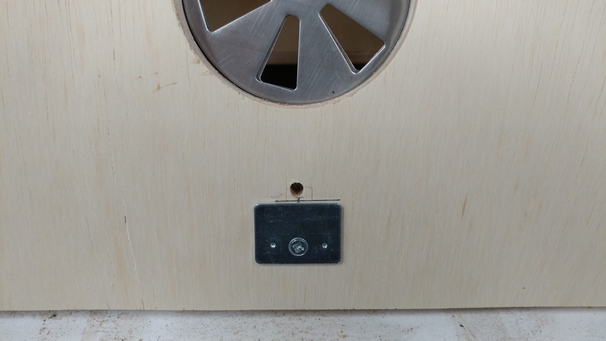
I then attached a handle to the door.
I also attached the door for the electrical in the same way except I didn’t attach a handle. I’ll explain why later.
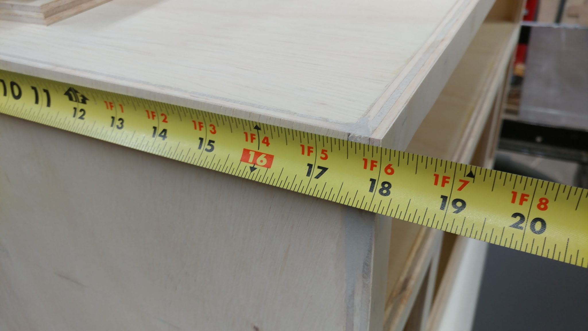
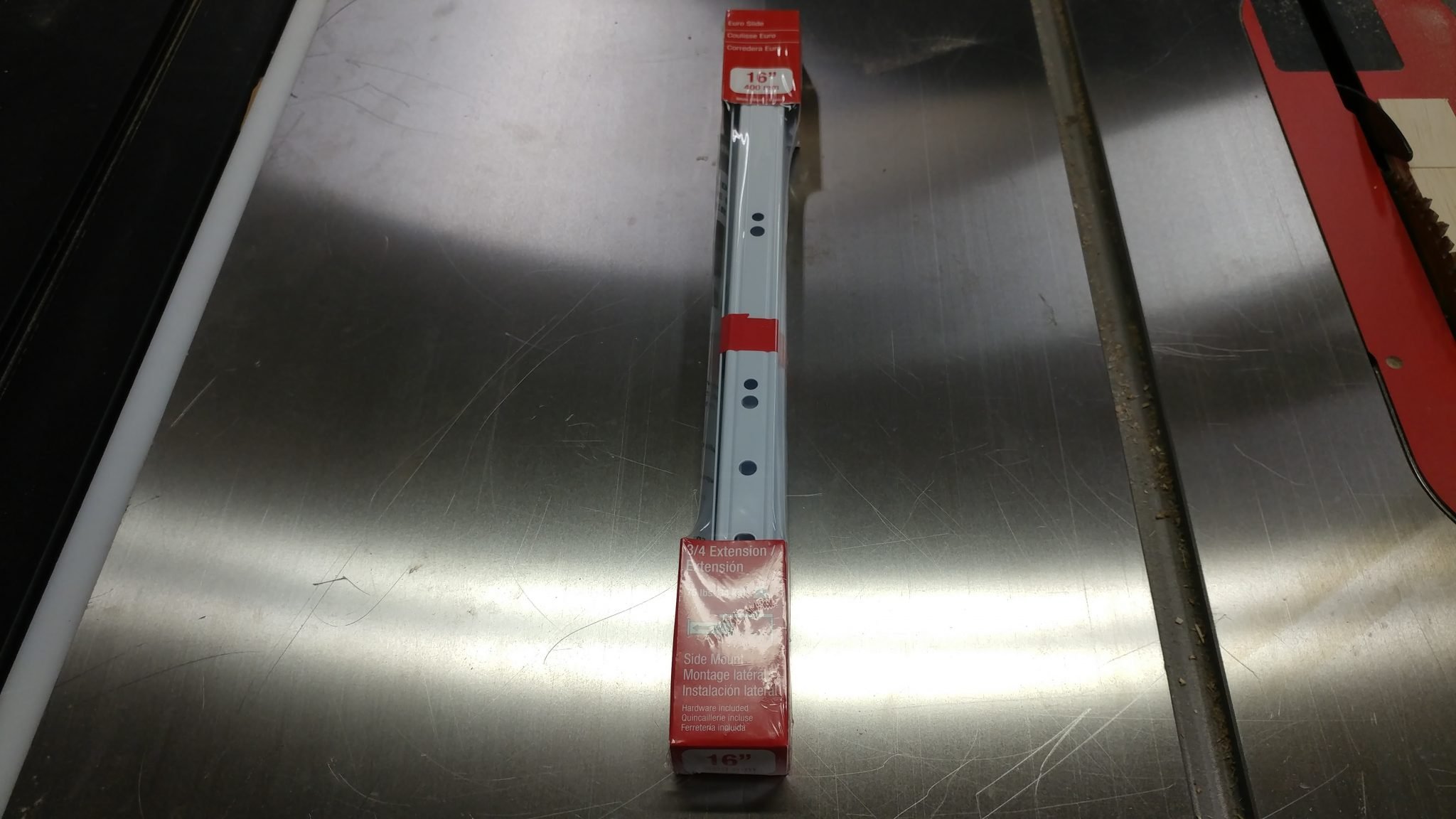
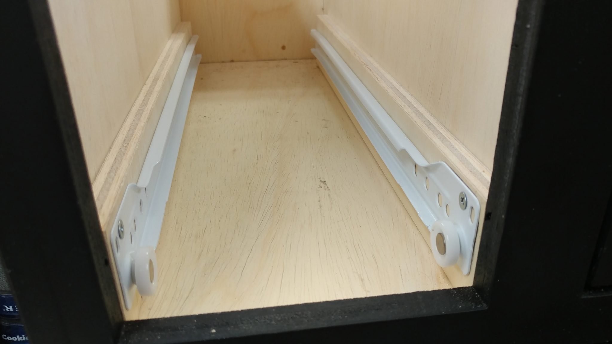
I decided to get cheap and I got some 16″ euro-style drawer glides.
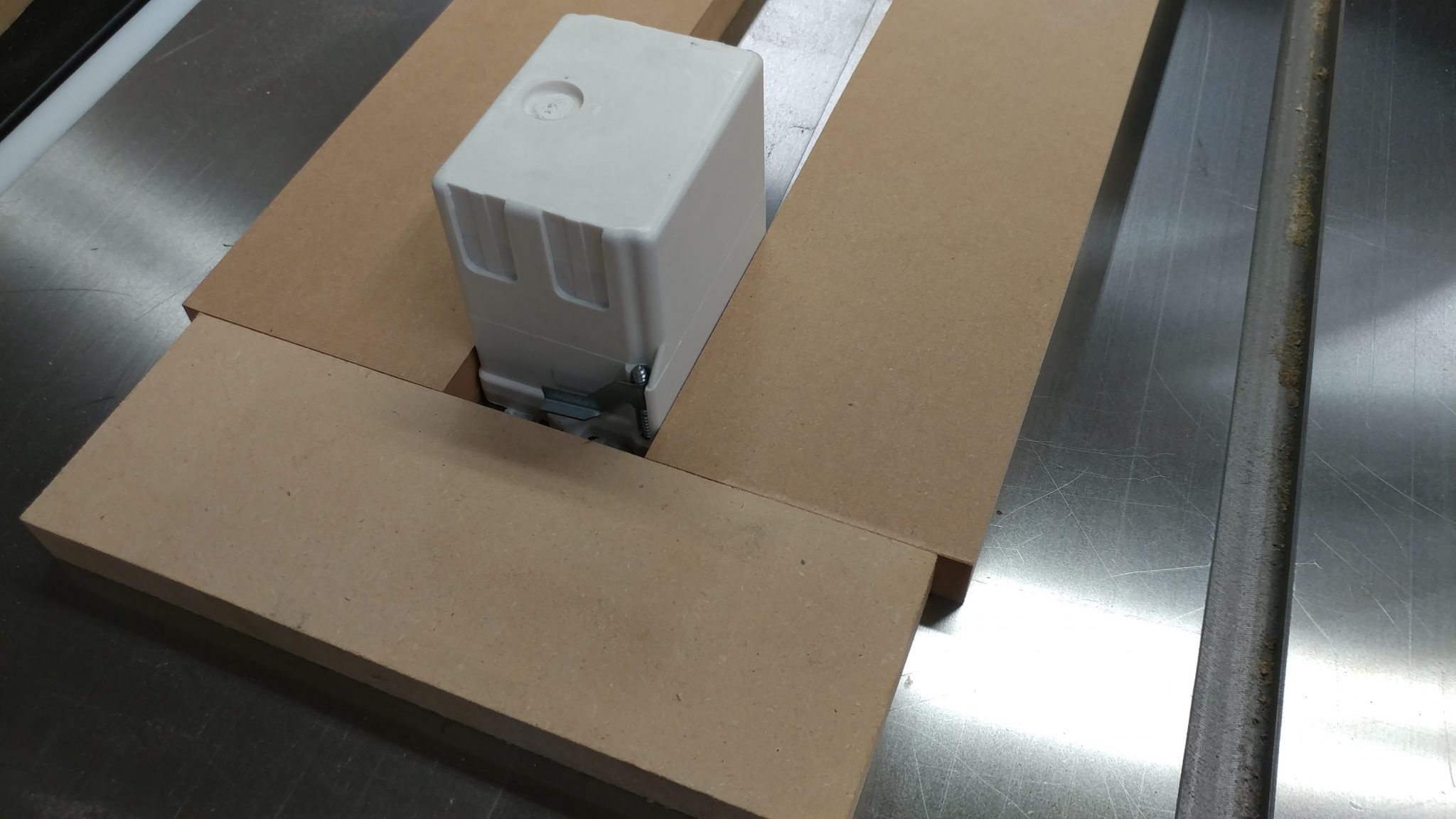
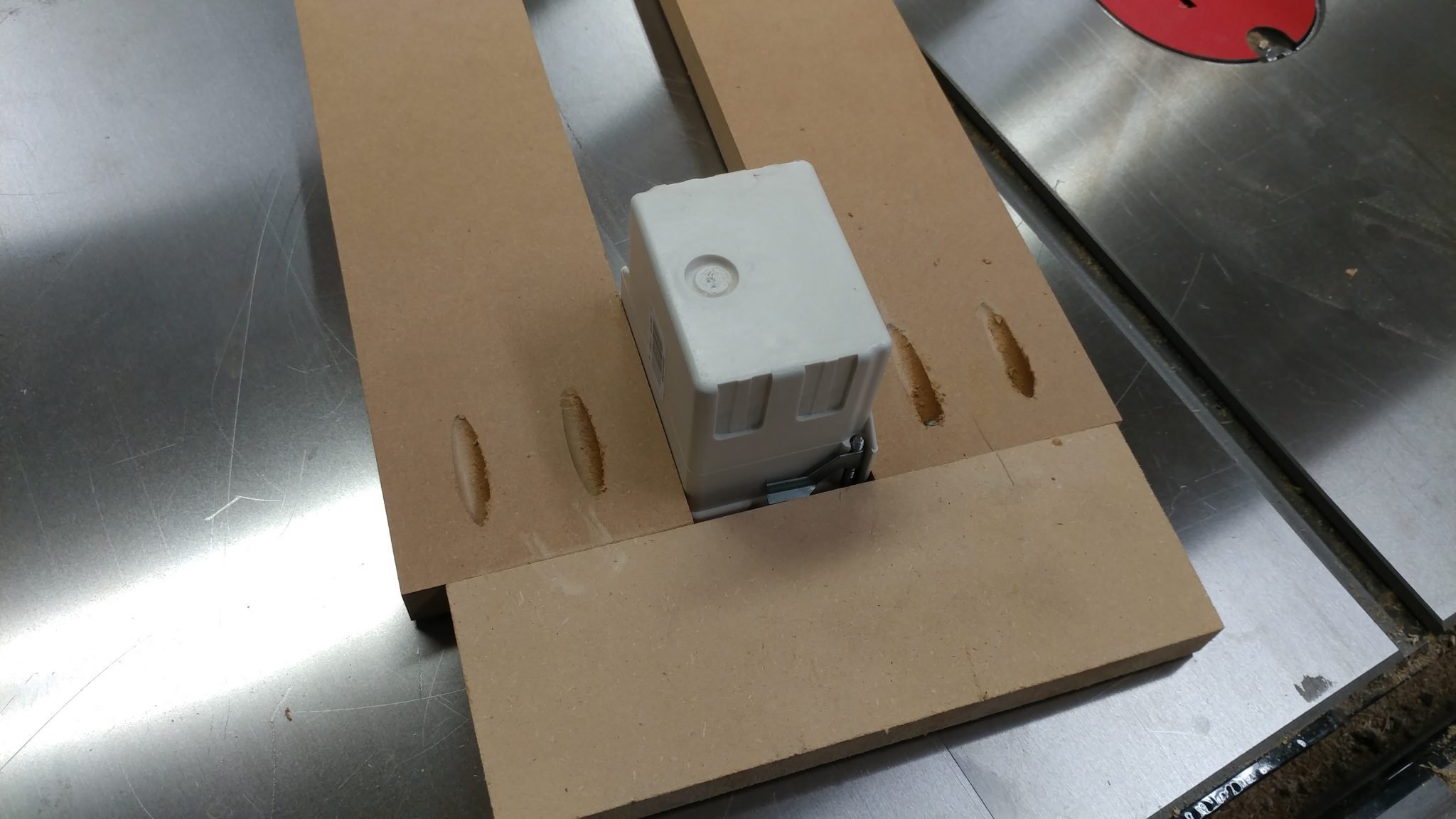
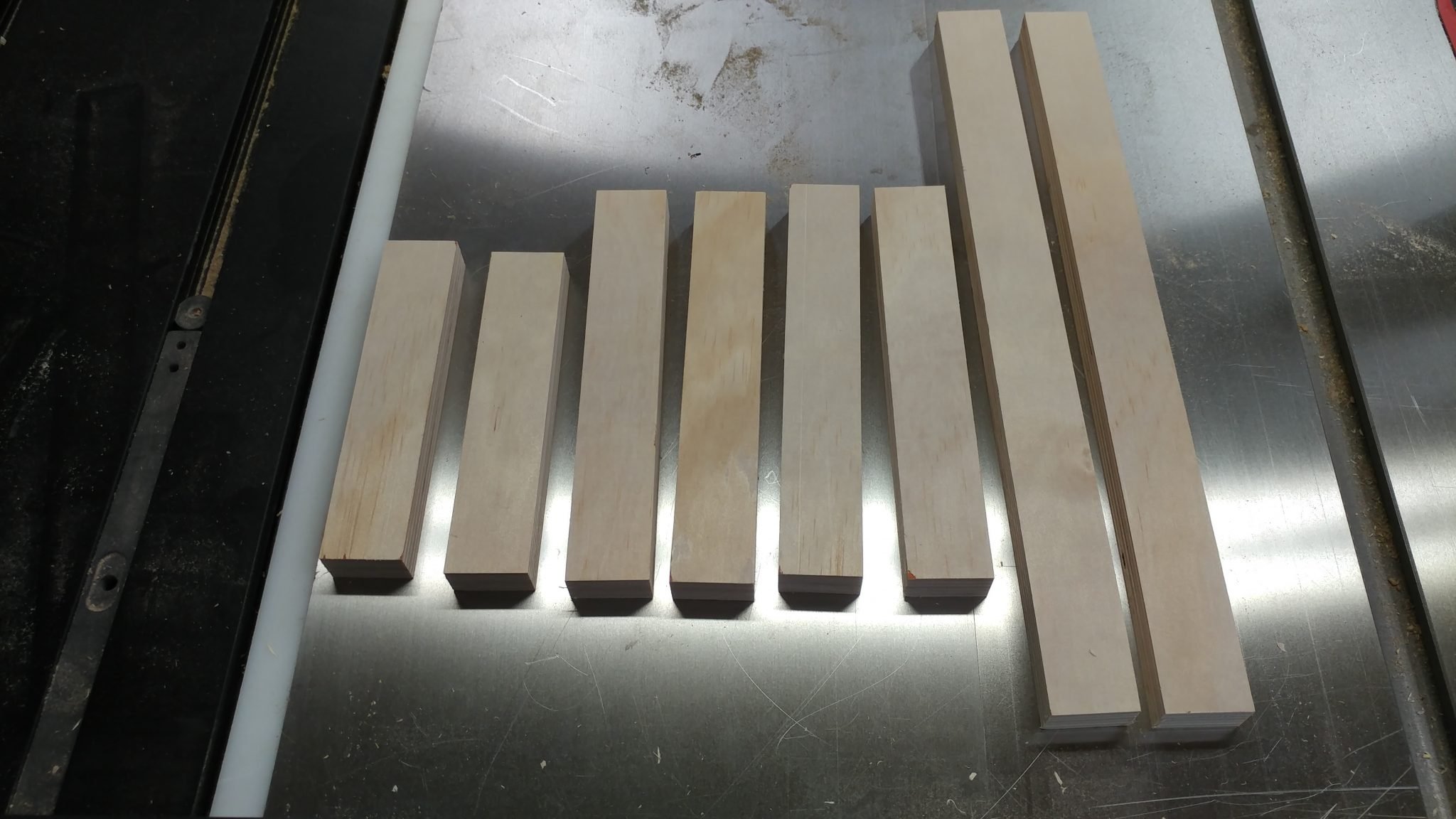
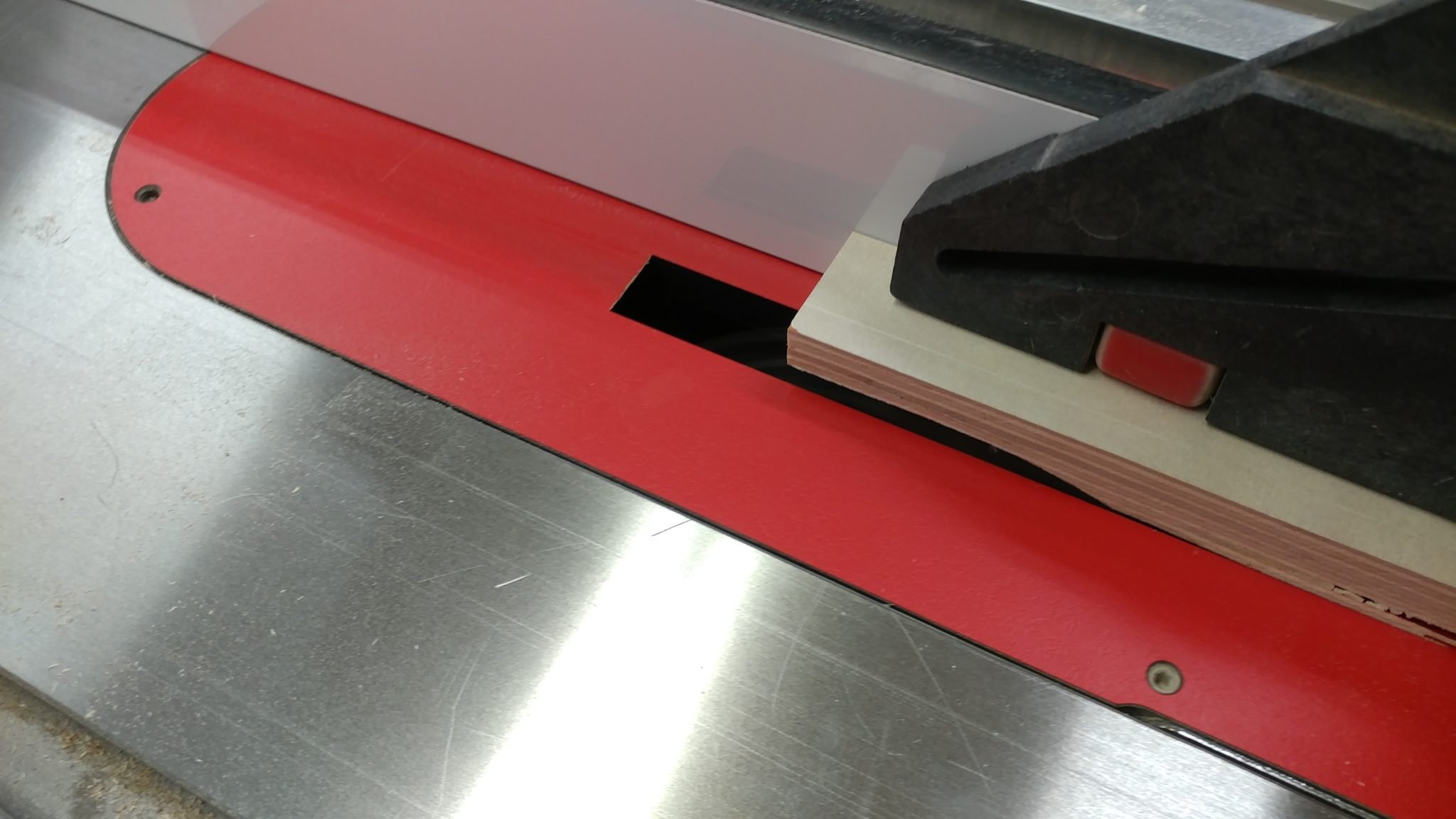
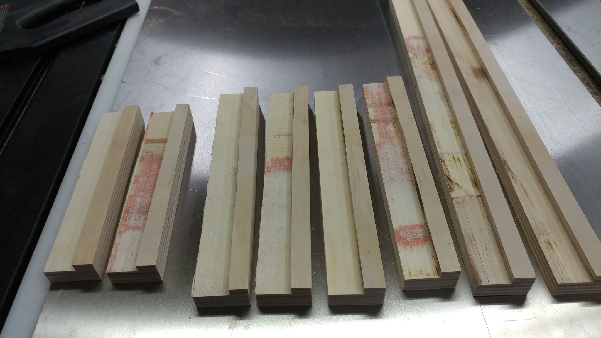
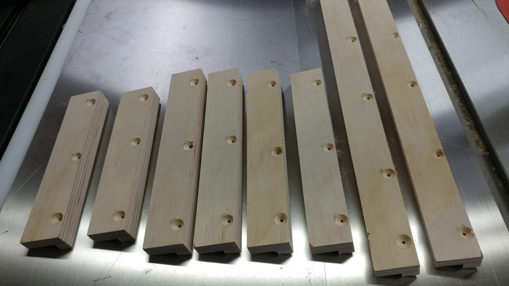
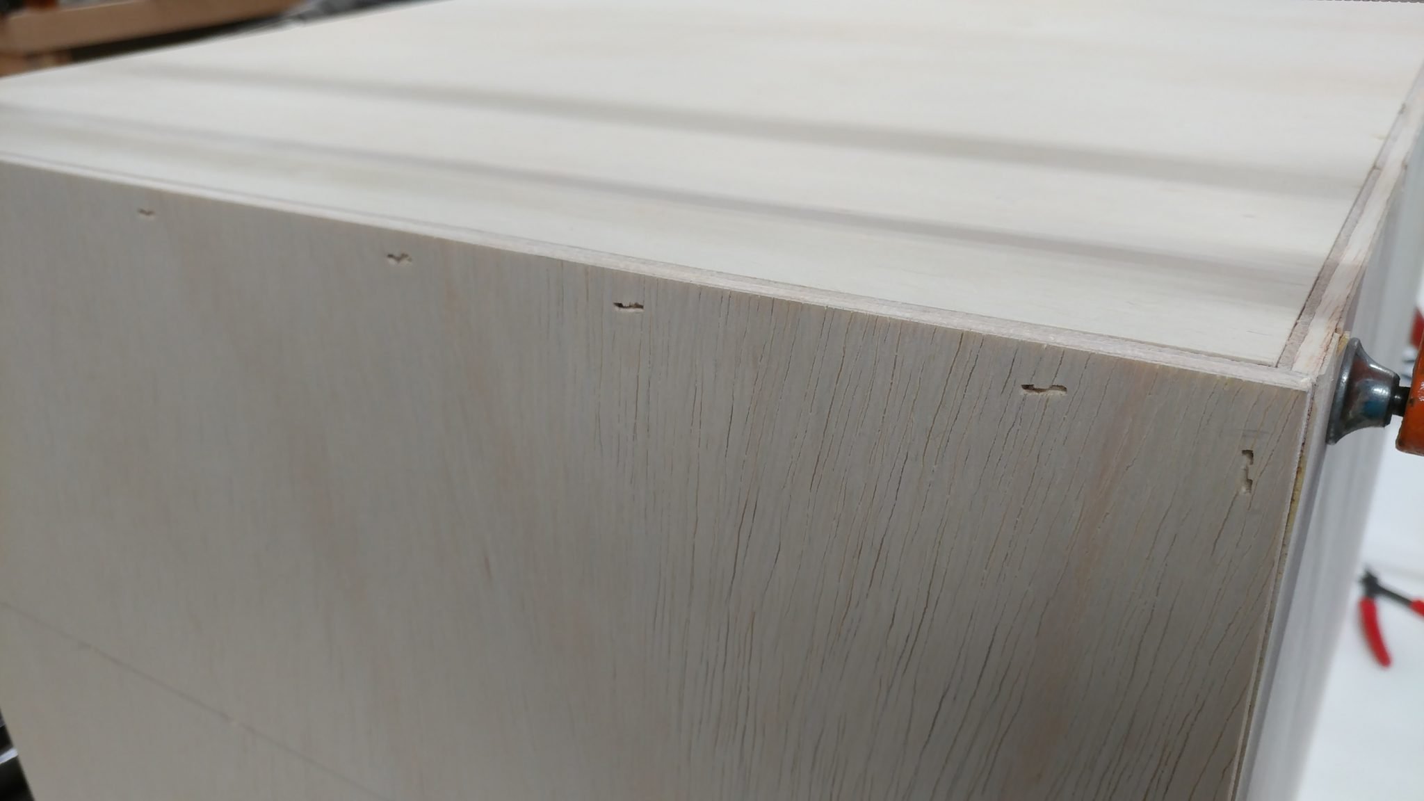
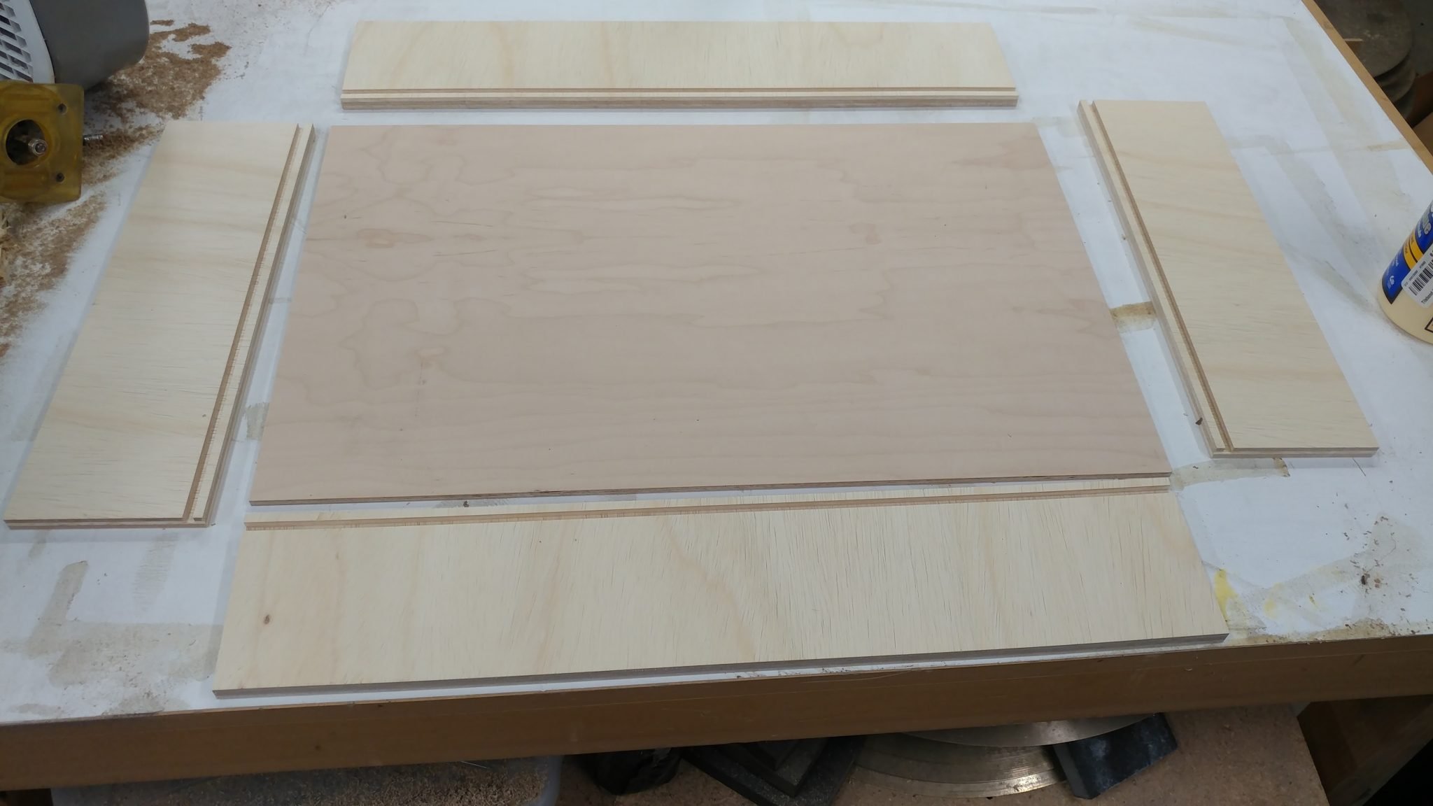
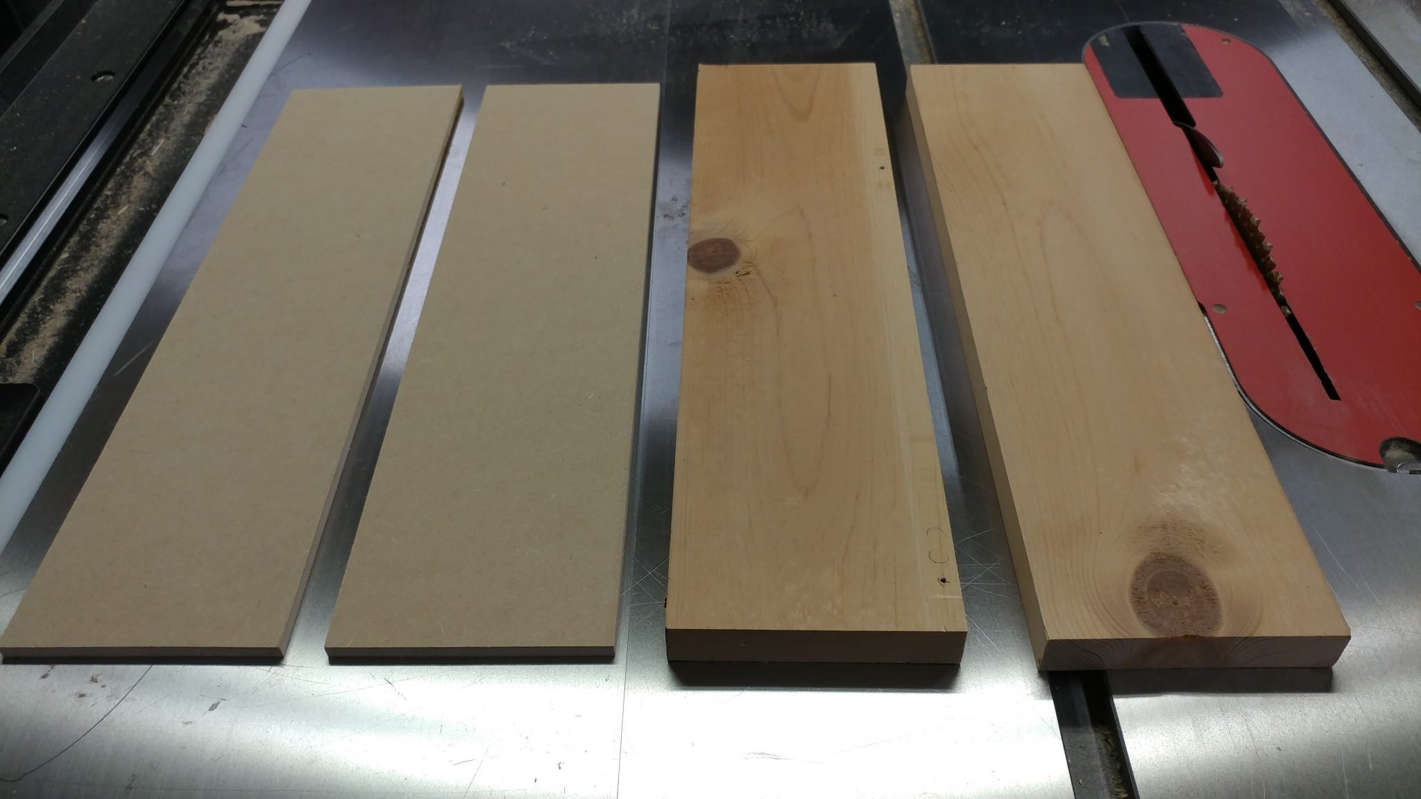
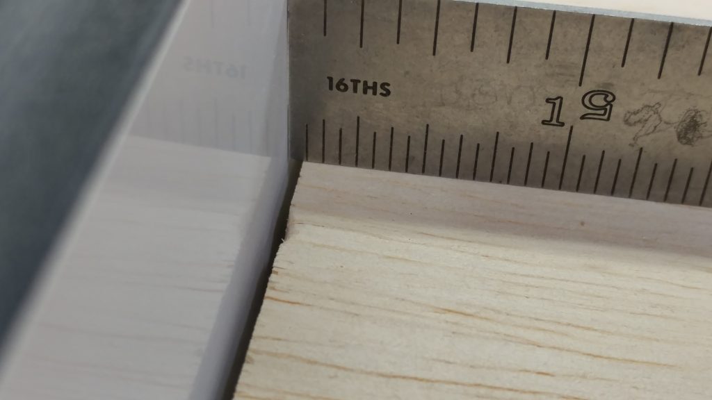
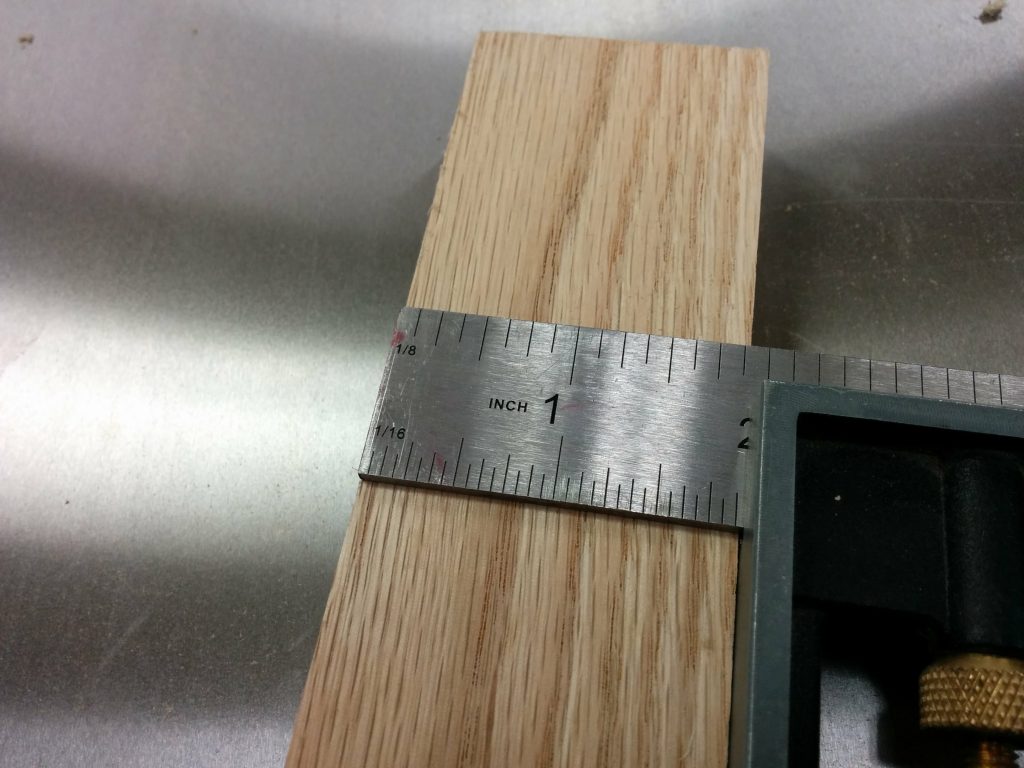
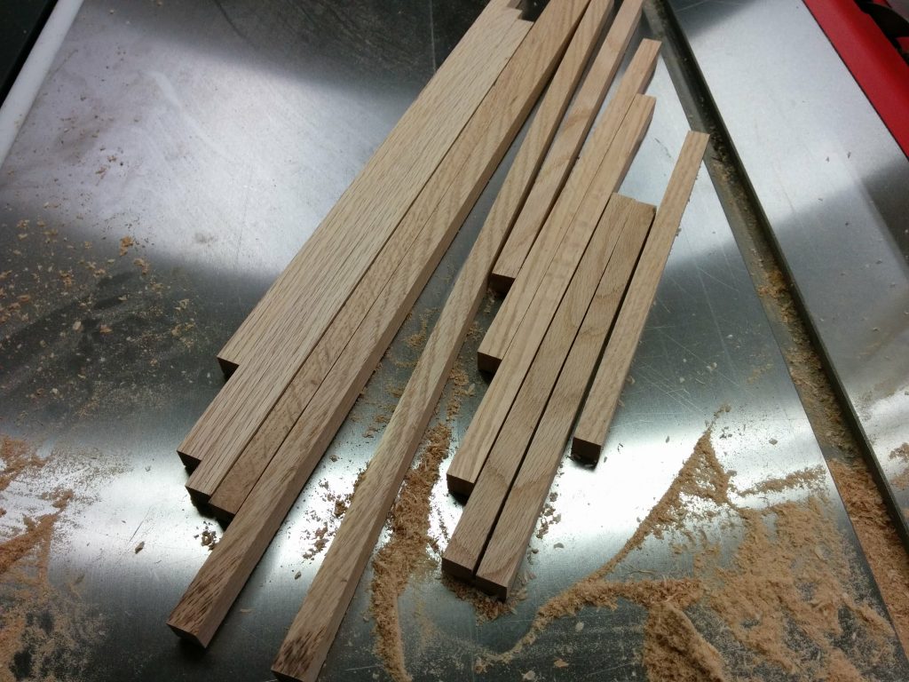
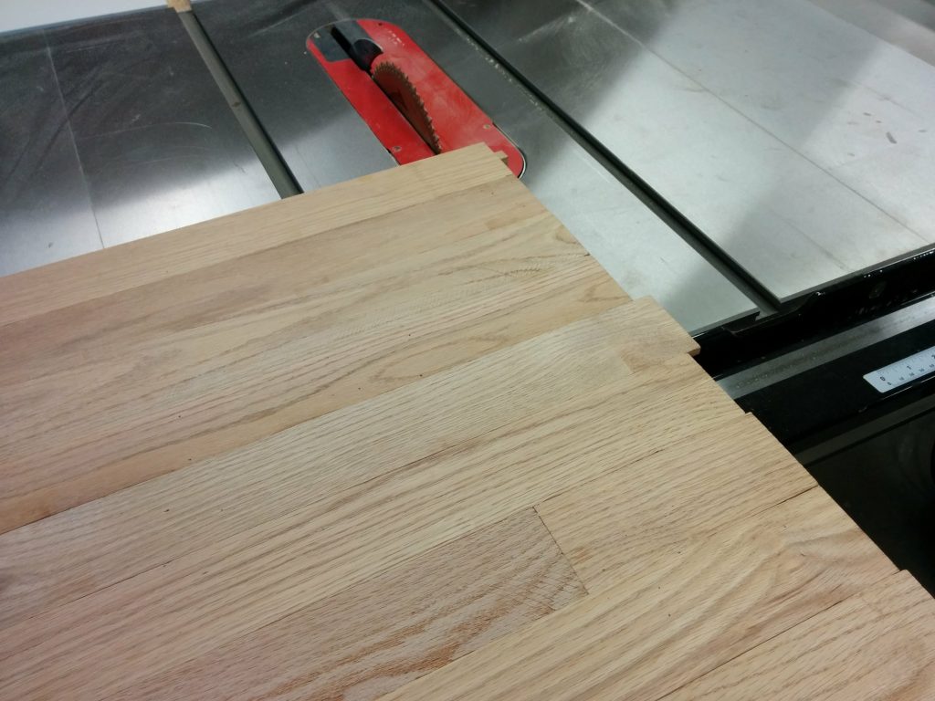
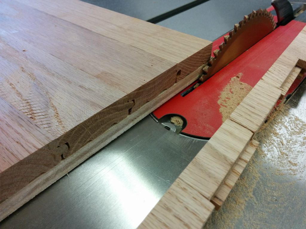
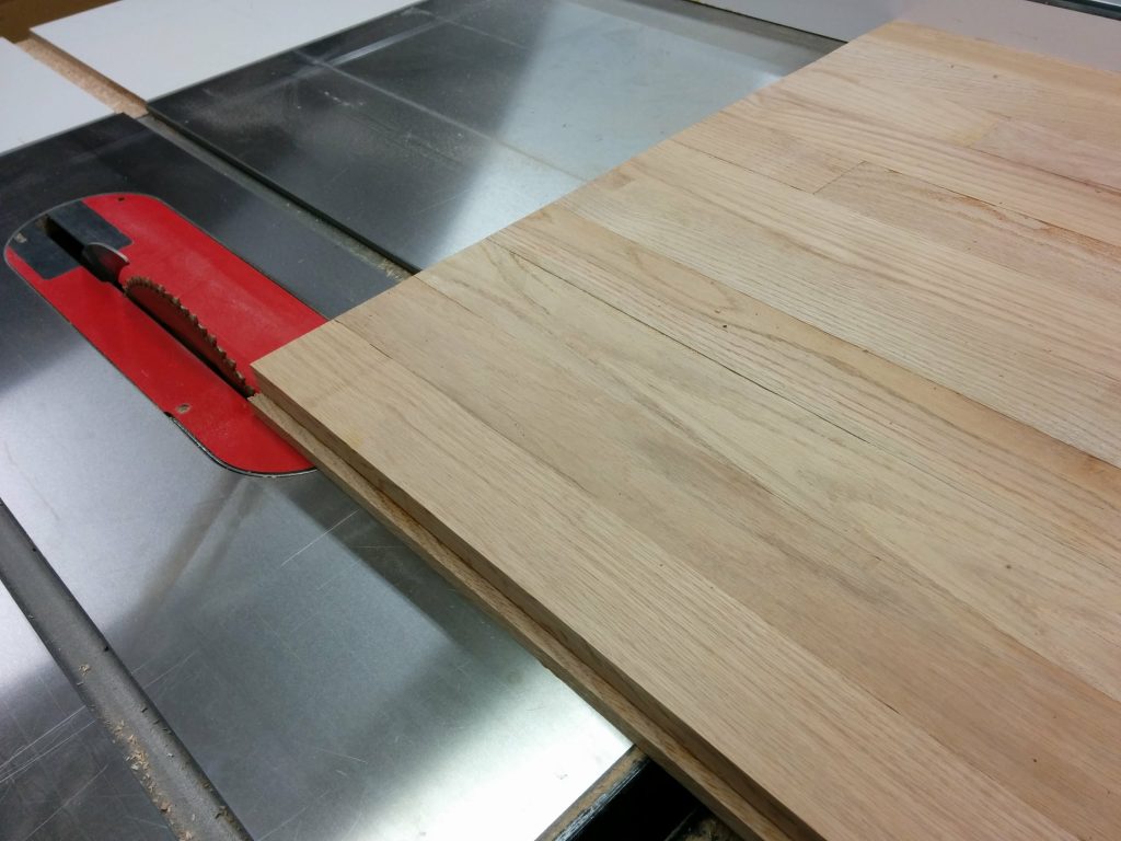
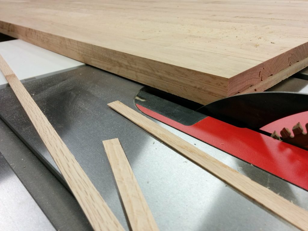
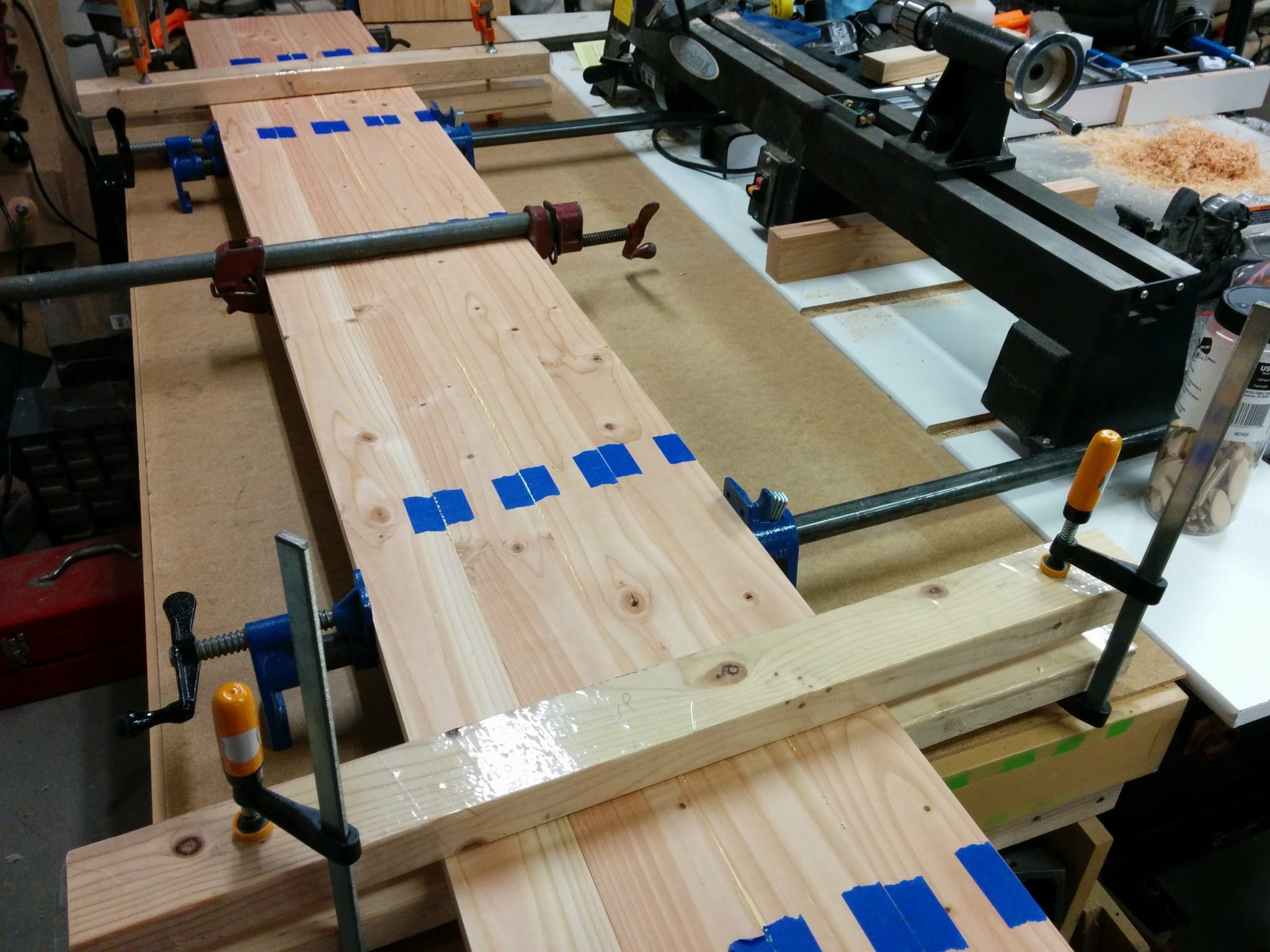
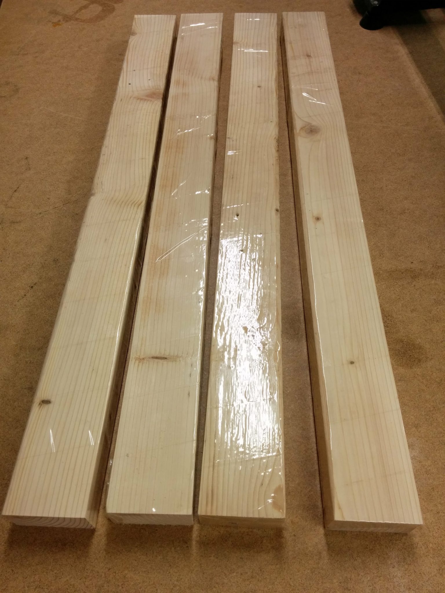
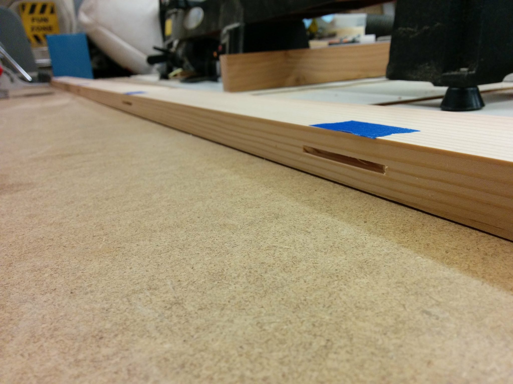
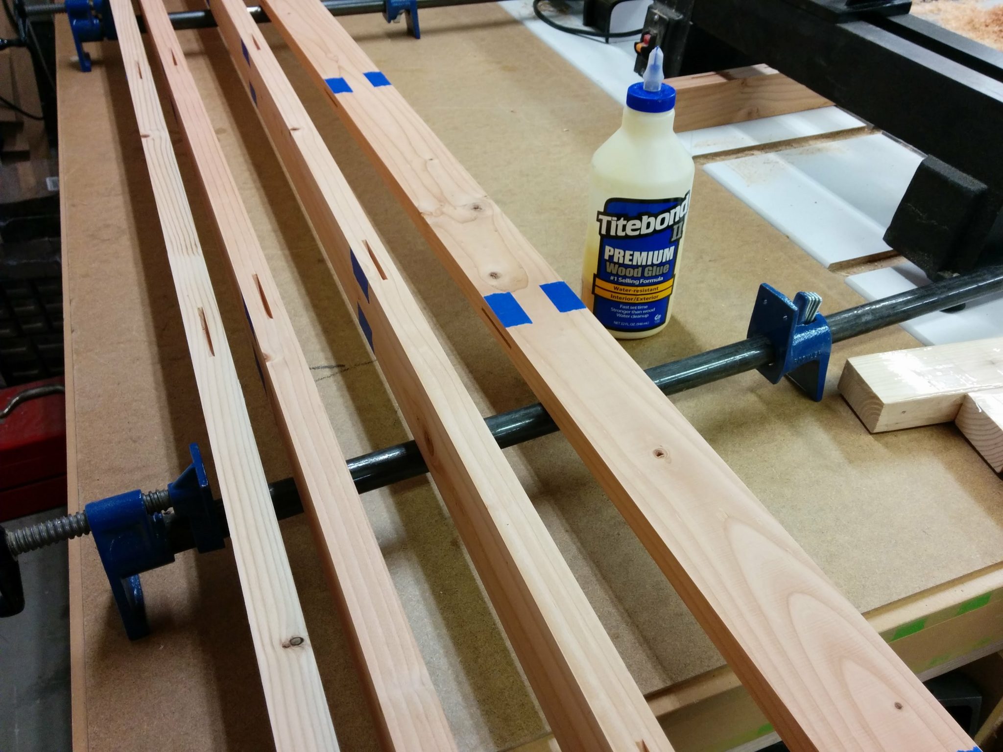
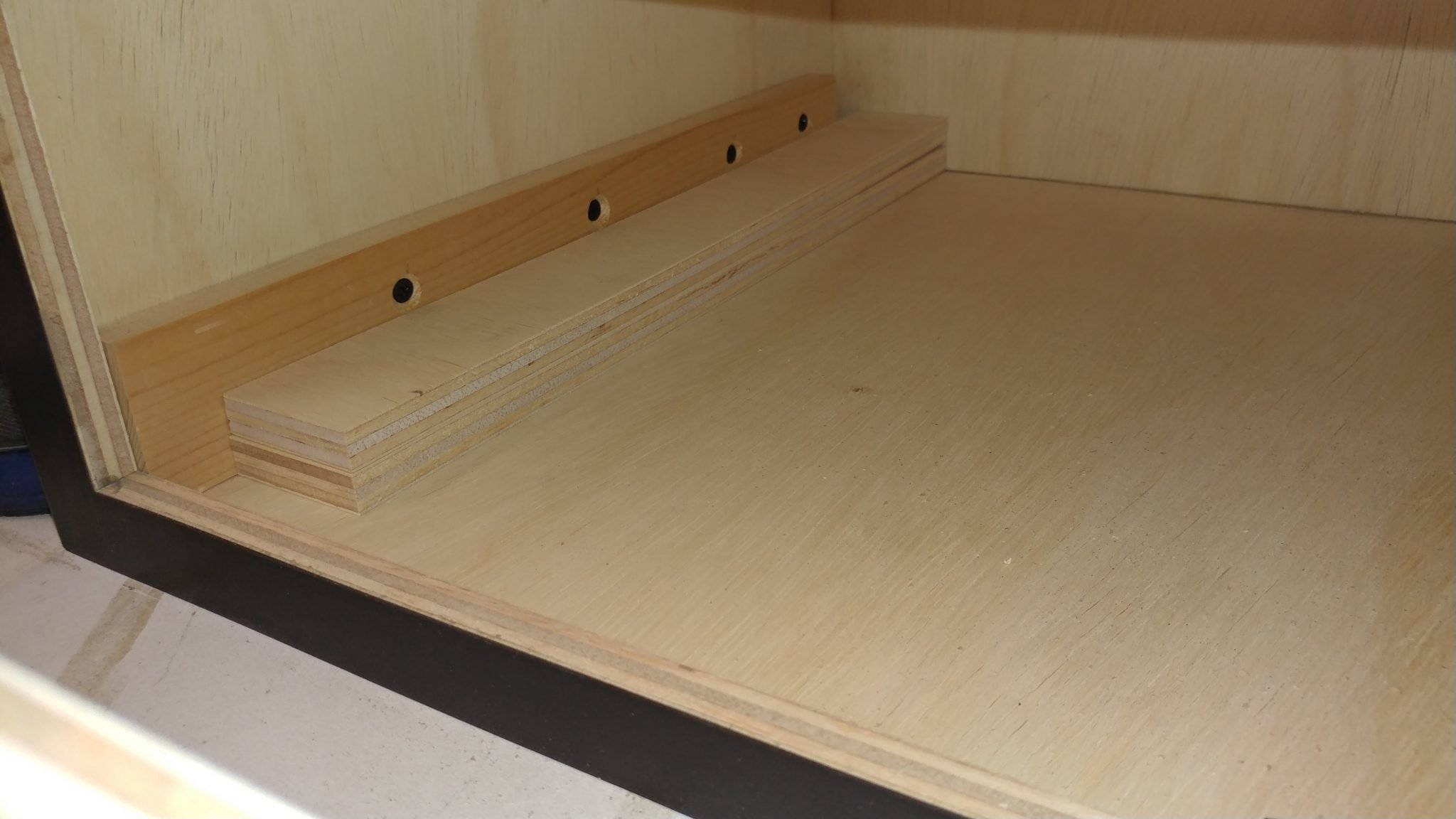
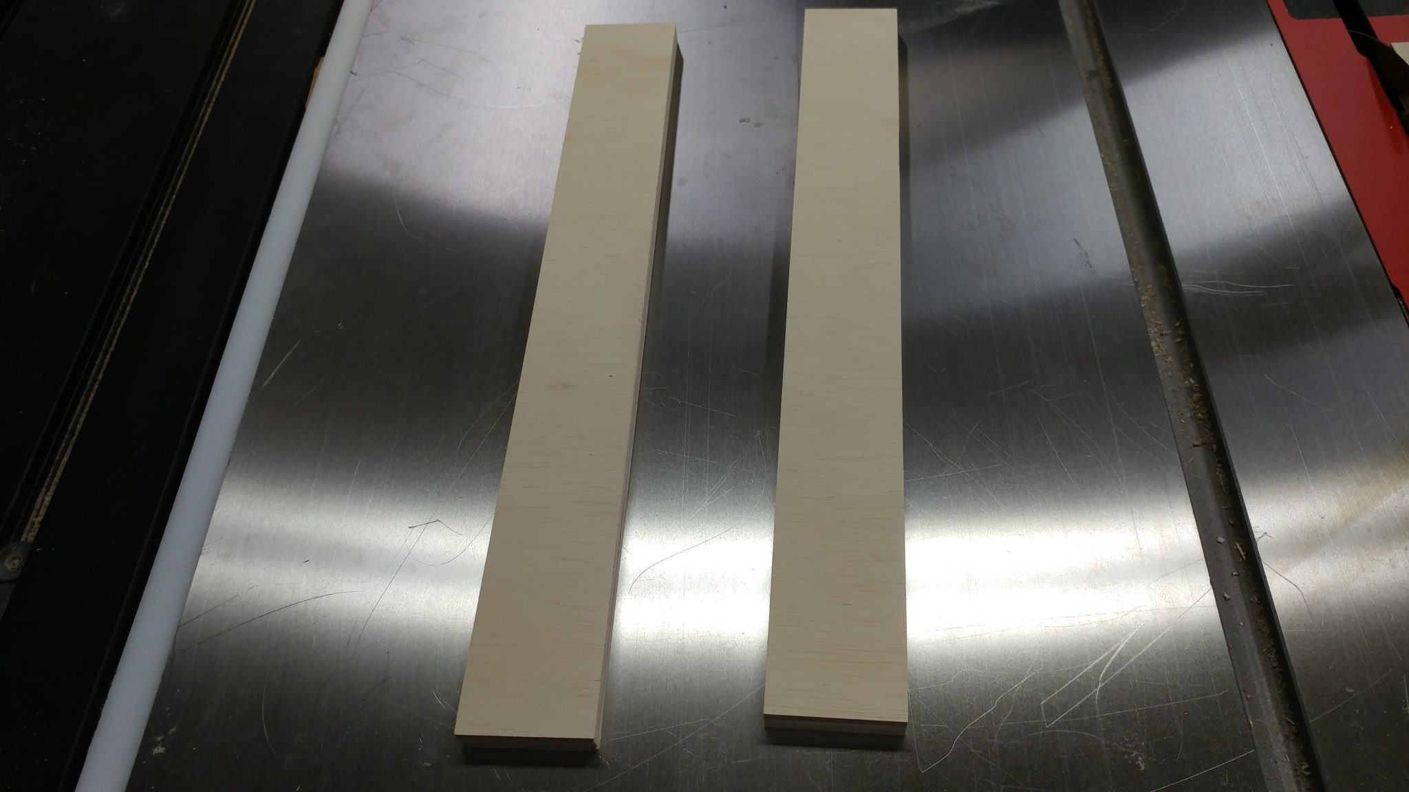
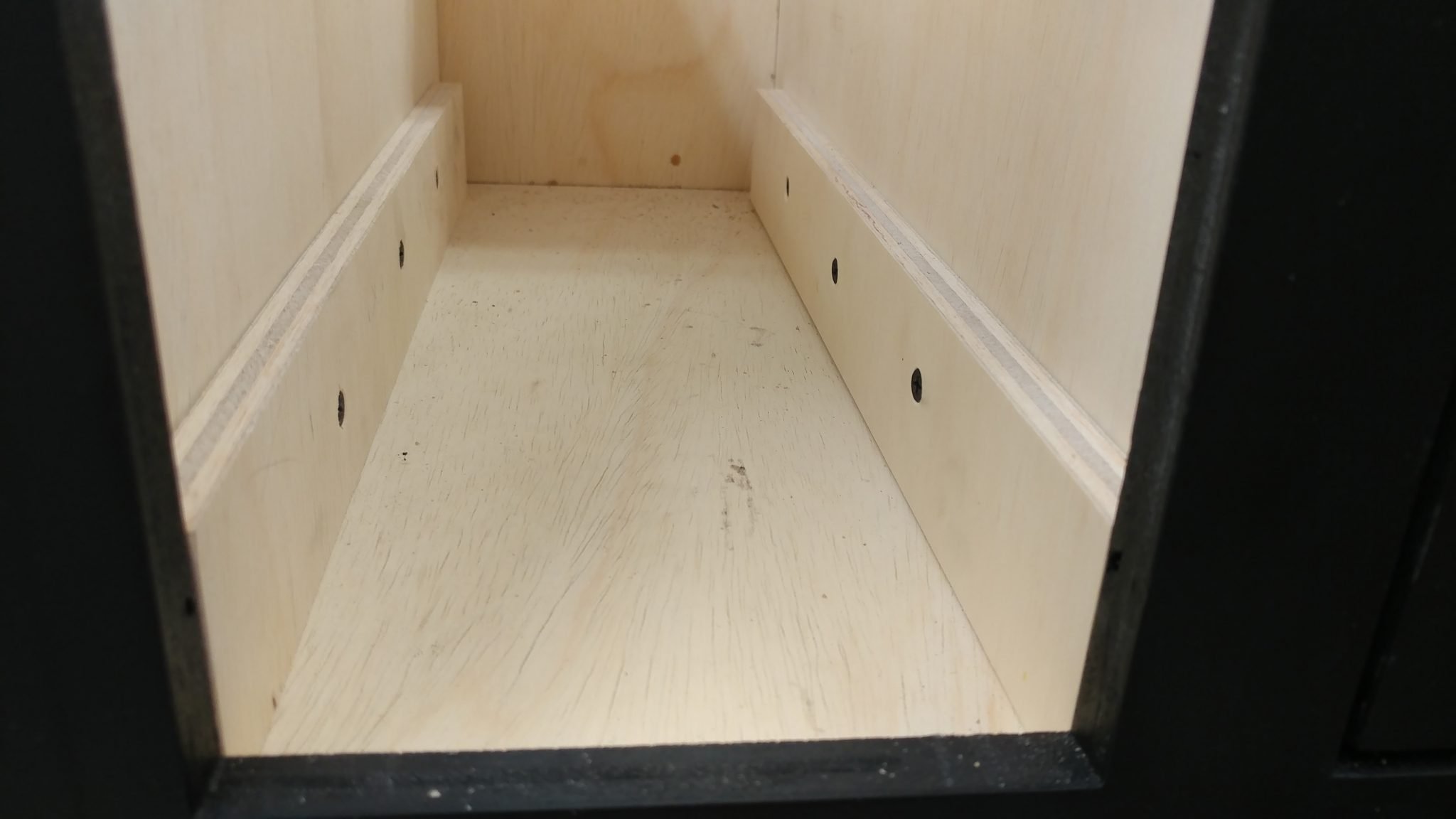
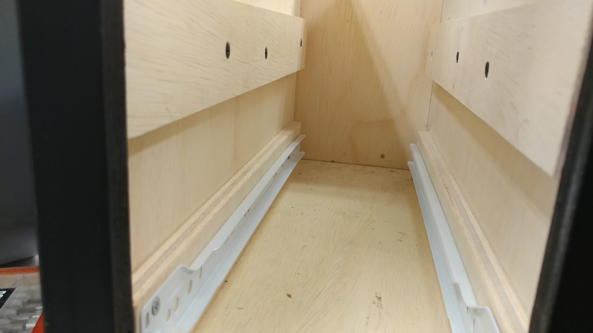
I need to thicken the walls of the carcase where I am attaching the drawer glides so I cut some wood strips 16″ long and 1-1/2″ tall and pre-drilled and countersunk some holes for drywall screws.
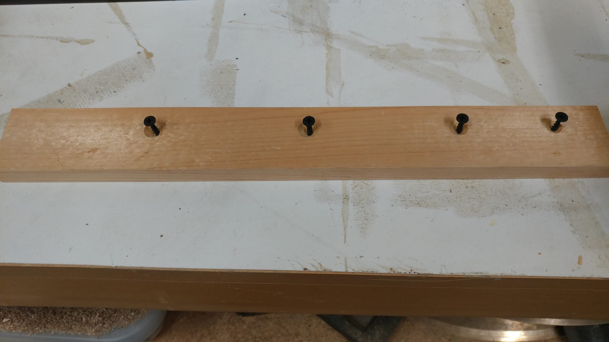
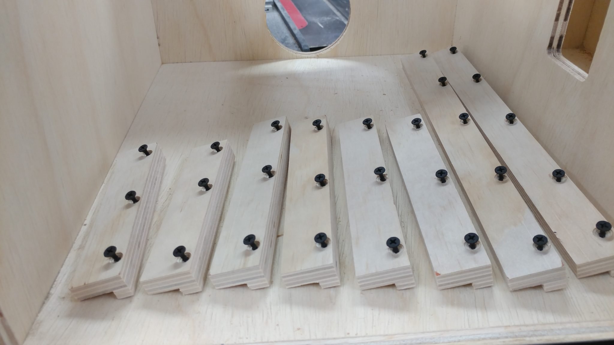
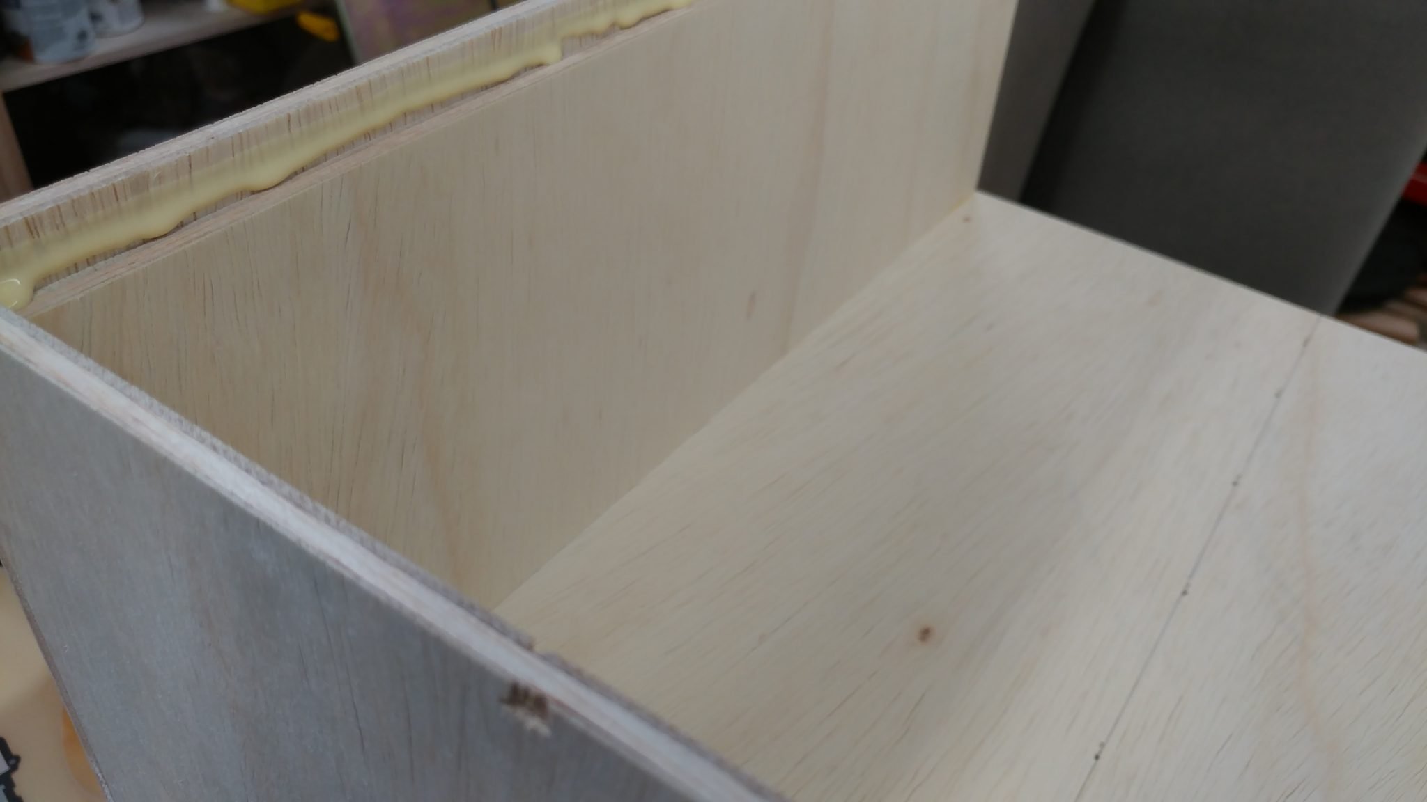
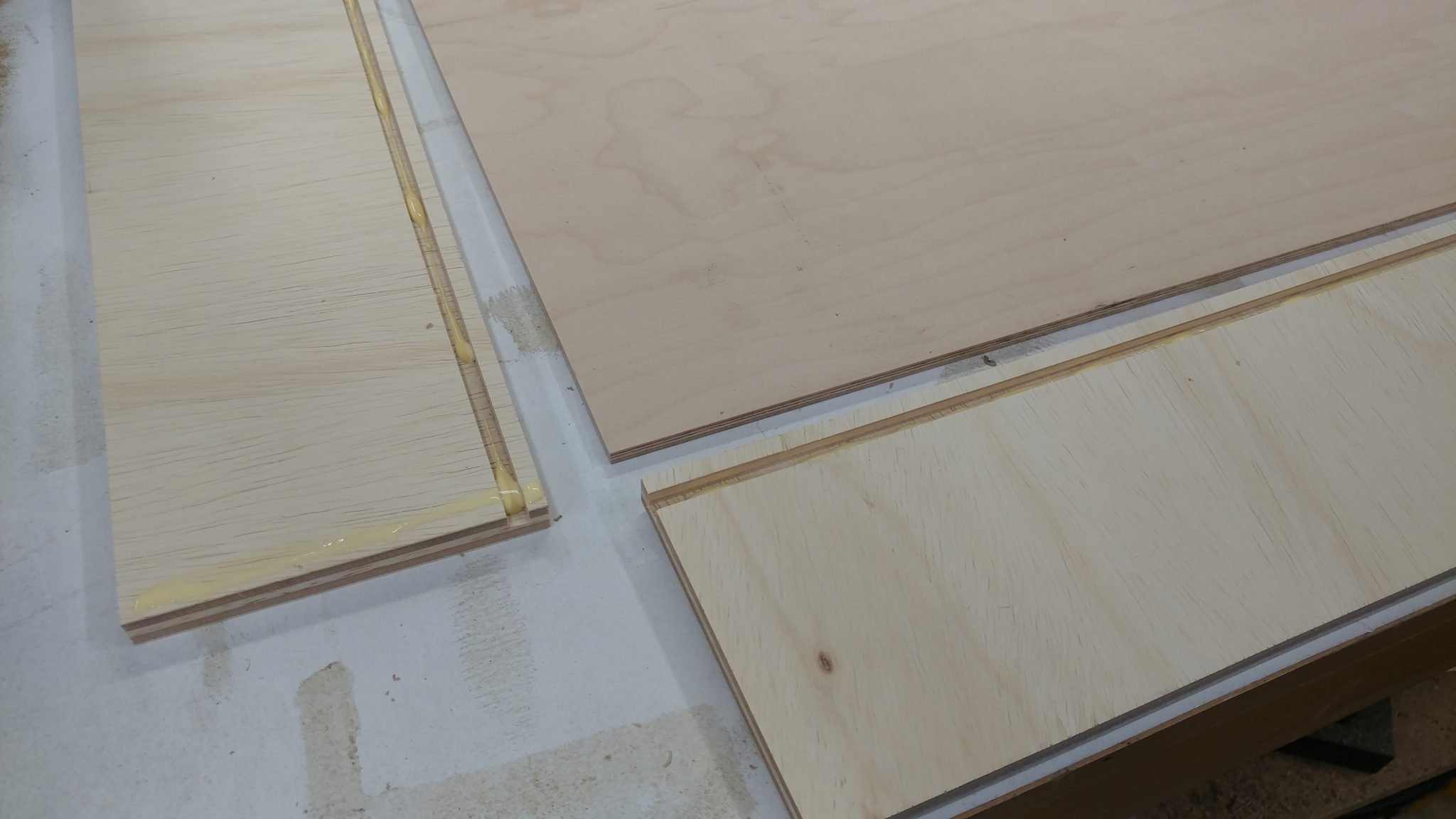
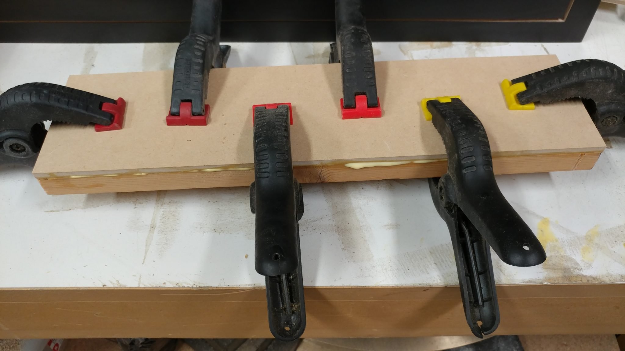
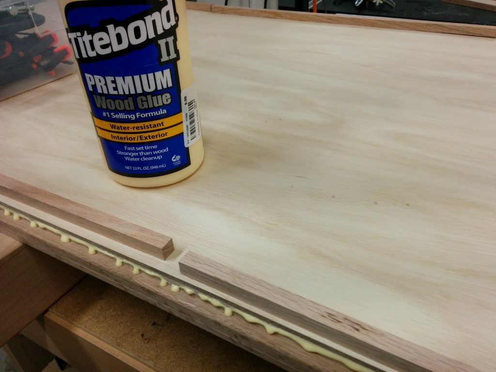
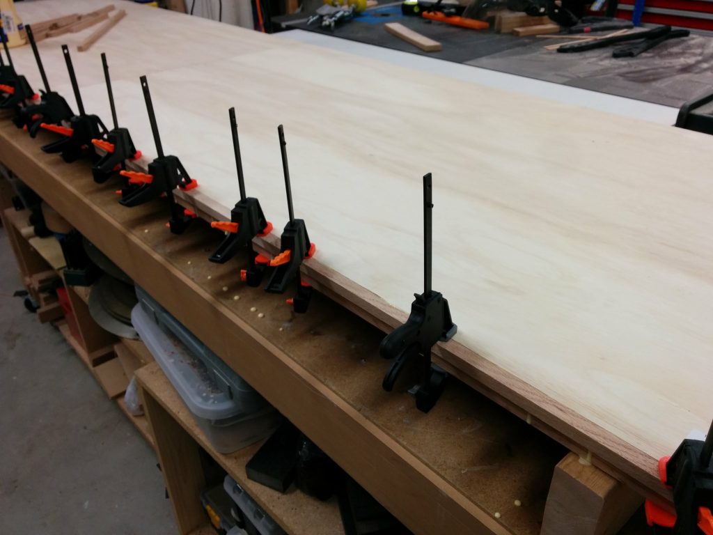
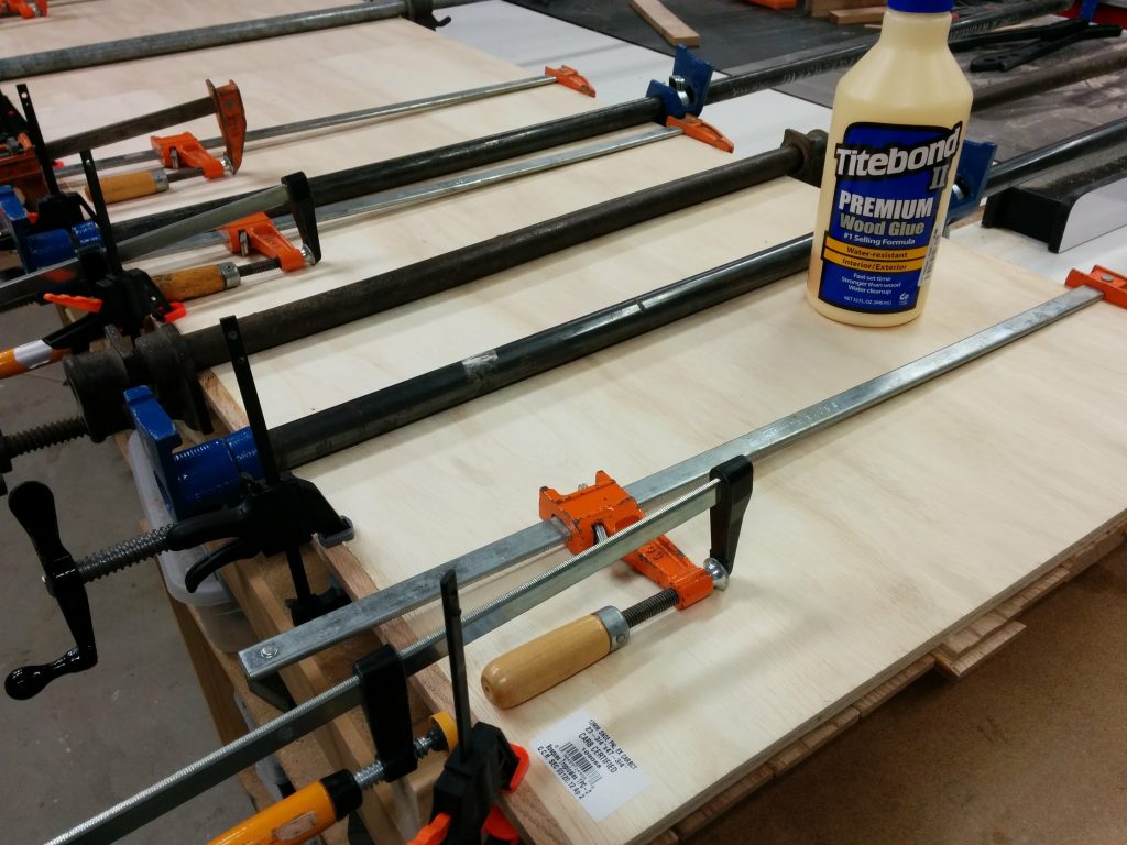
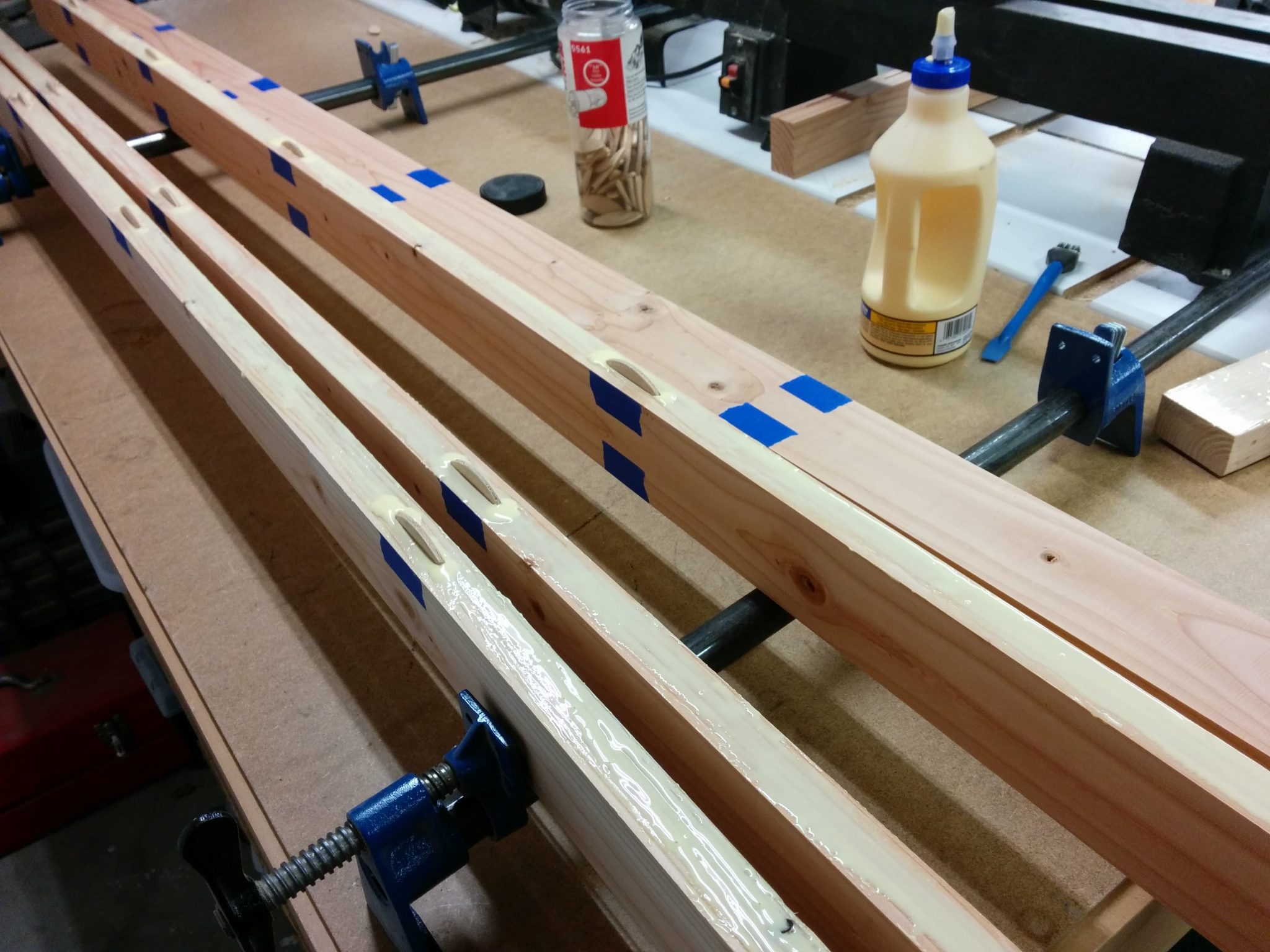
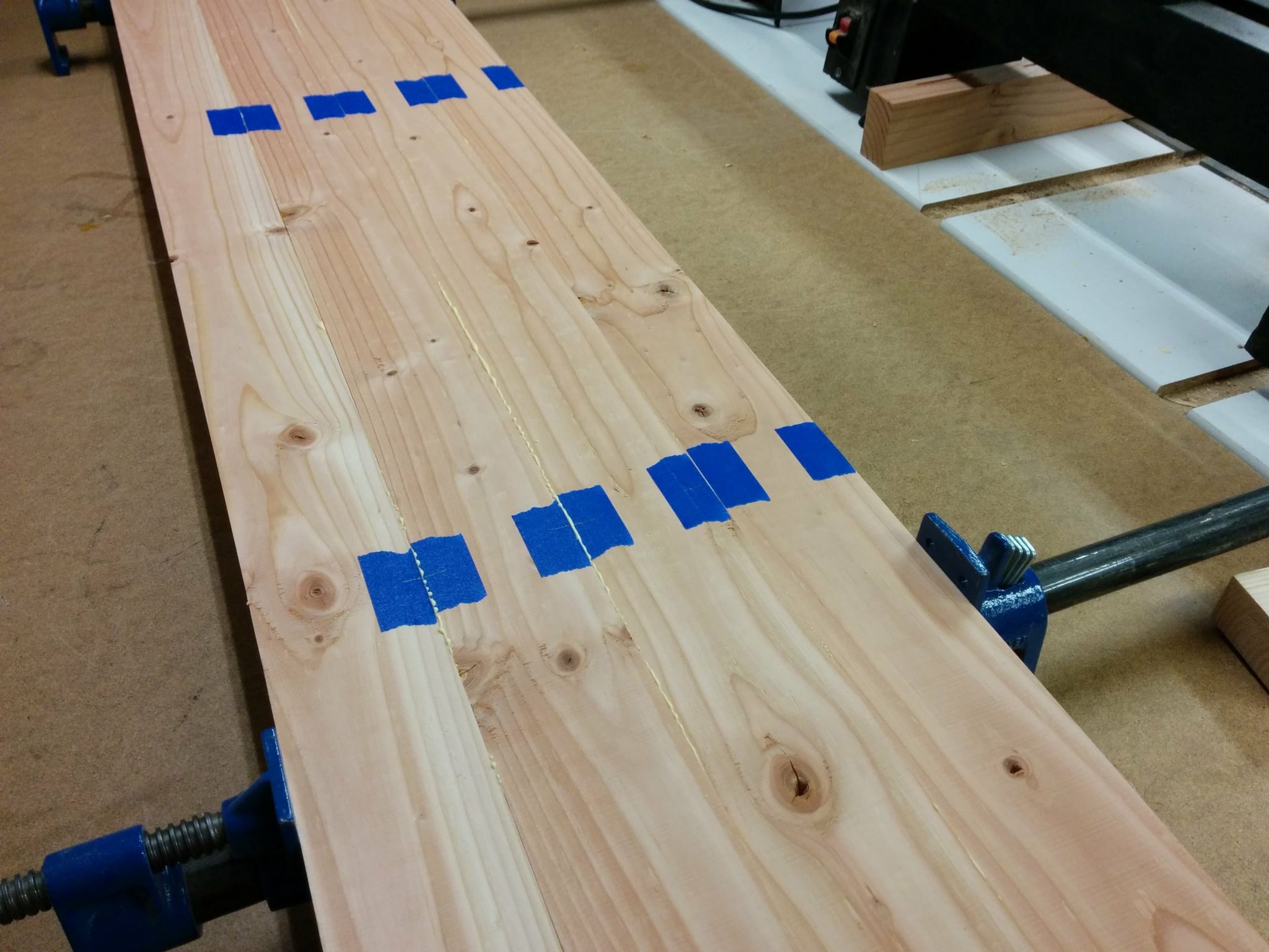
I then glued and screwed these to the inside of the carcase everywhere the drawer glides will be attached. The screw placement may seem random but it isn’t. They are arranged so they won’t interfere with the screws for mounting the drawer glides.
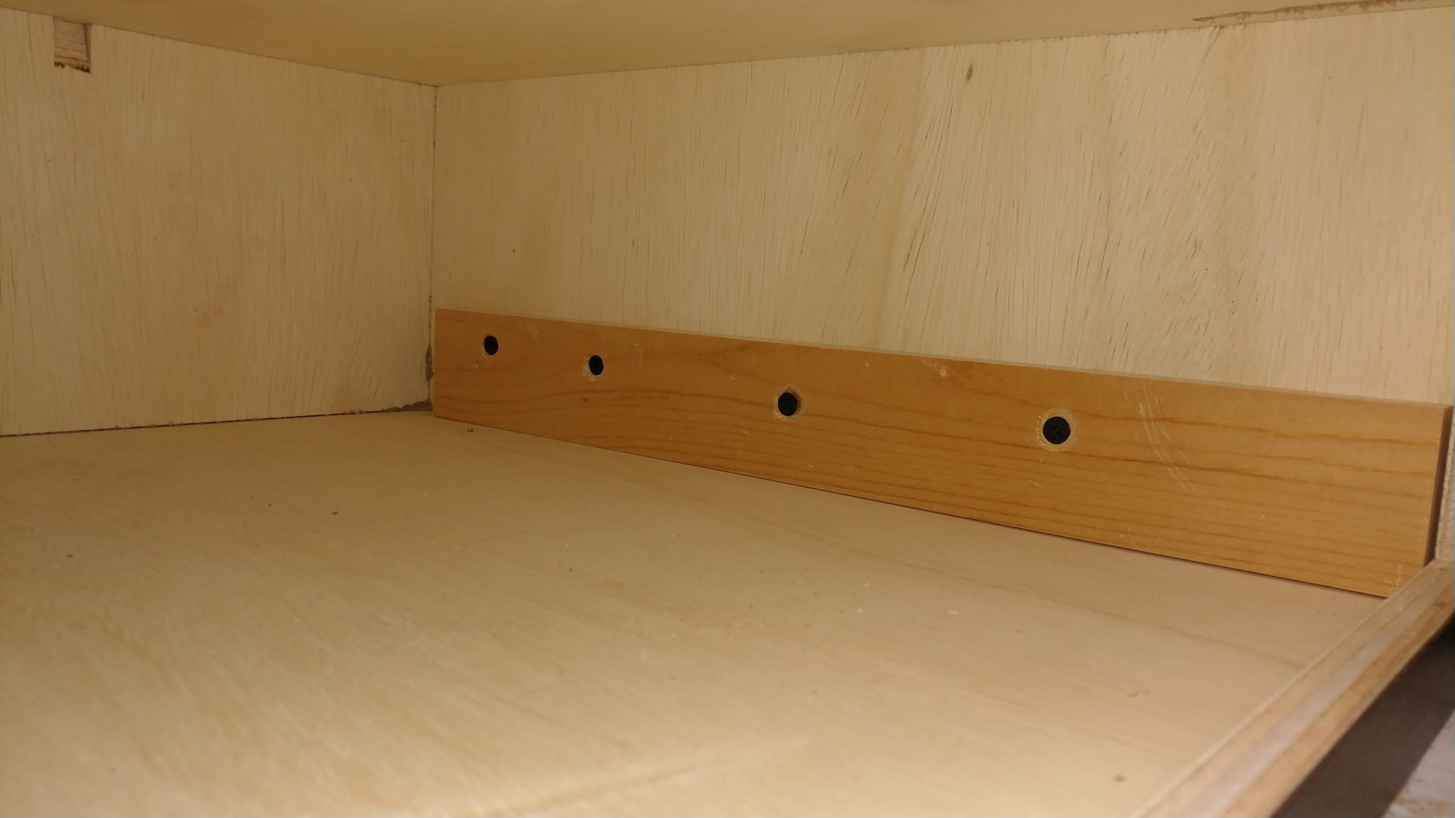
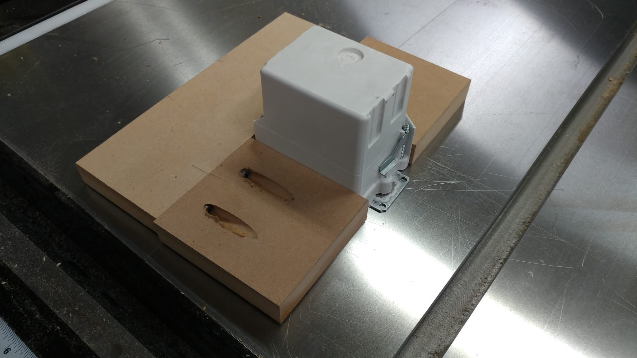
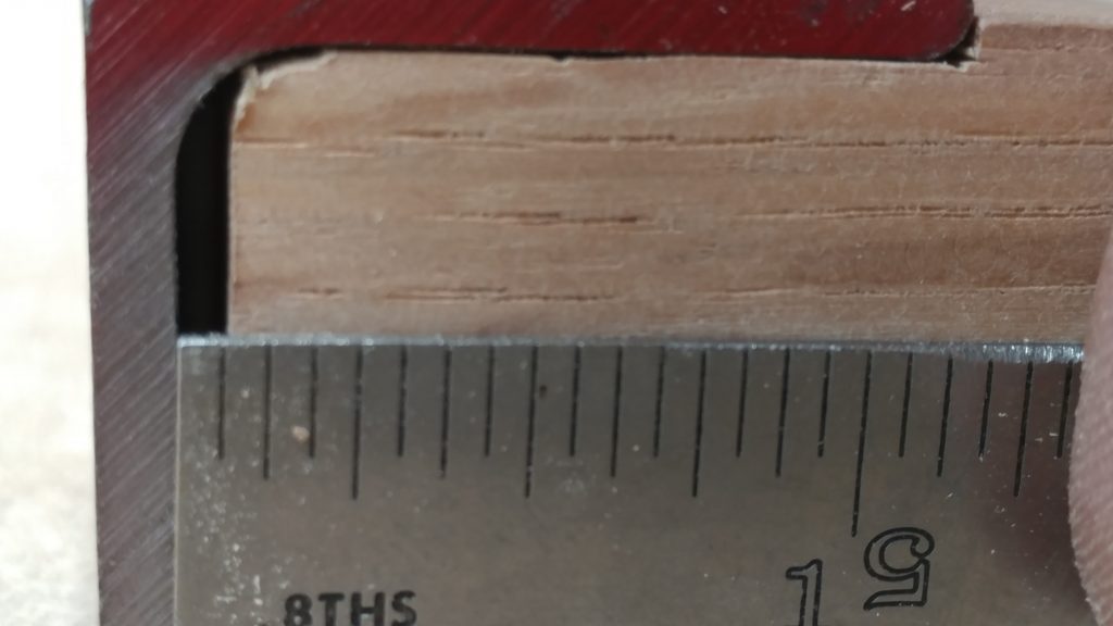
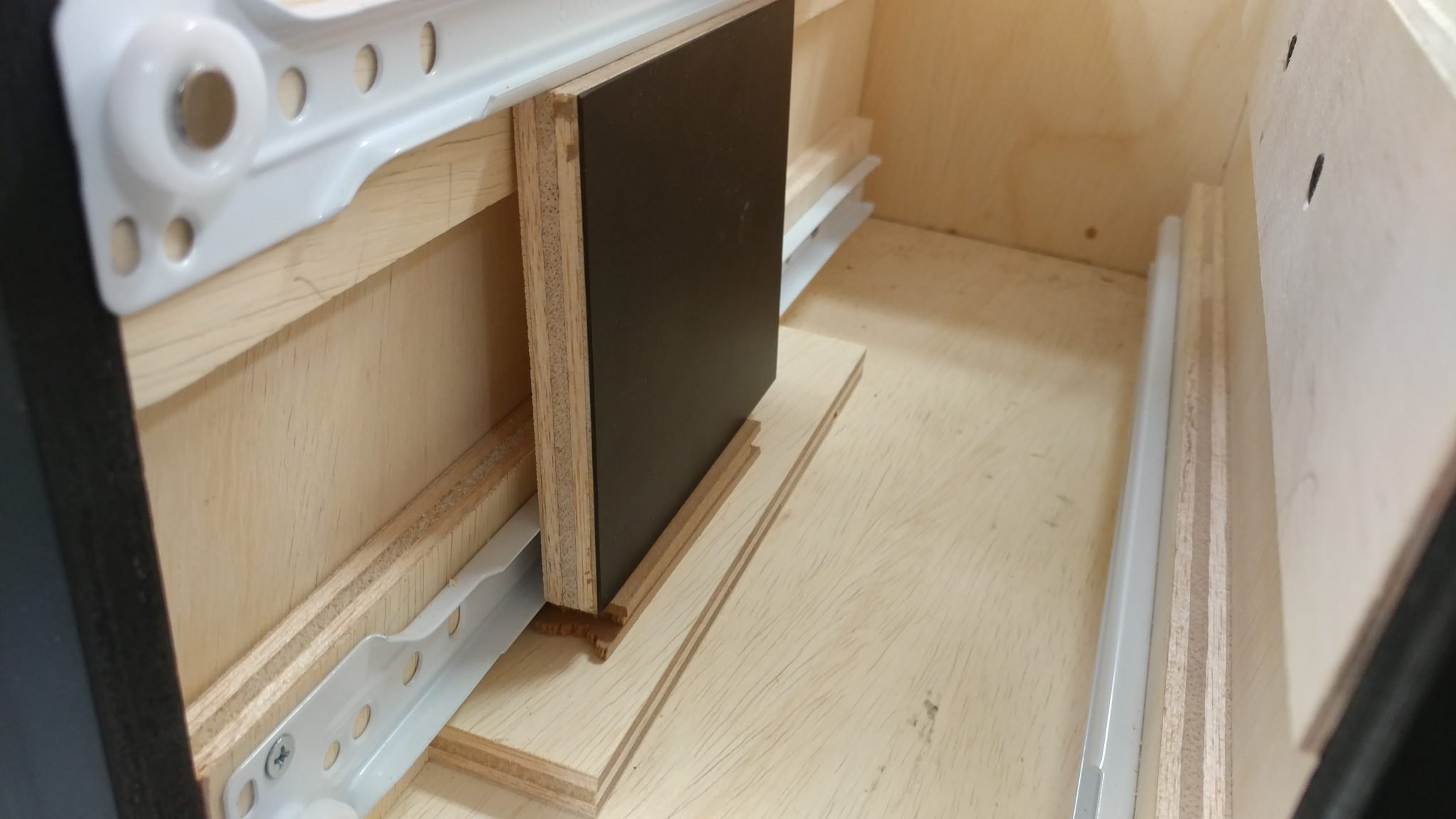
Due to a mis-measurement when I cut the pieces for the big drawer, I needed these pieces to be 5/8″ thick rather than 1/2″ thick as planned. Here they are in place with the drawer sitting roughly in place.
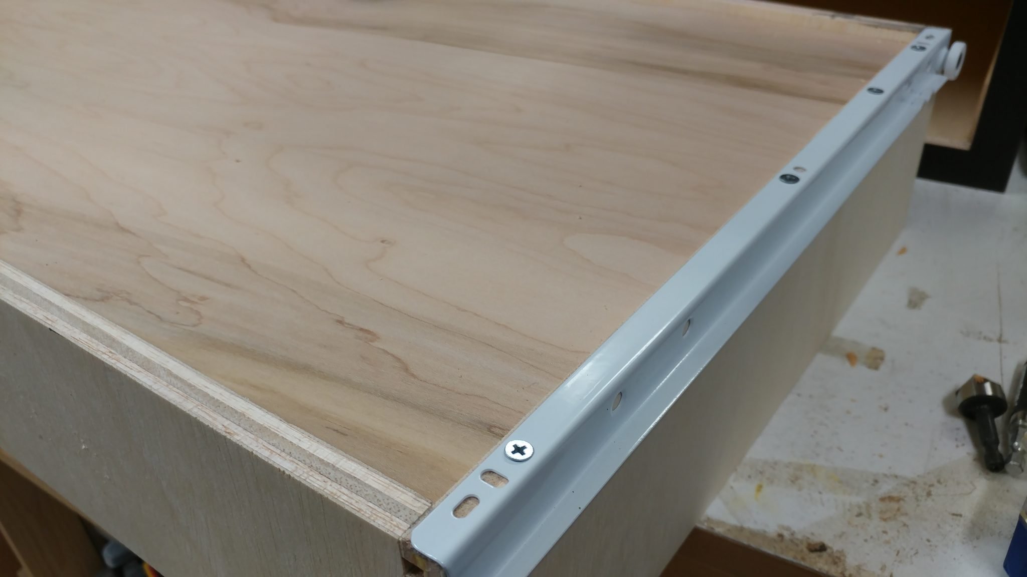
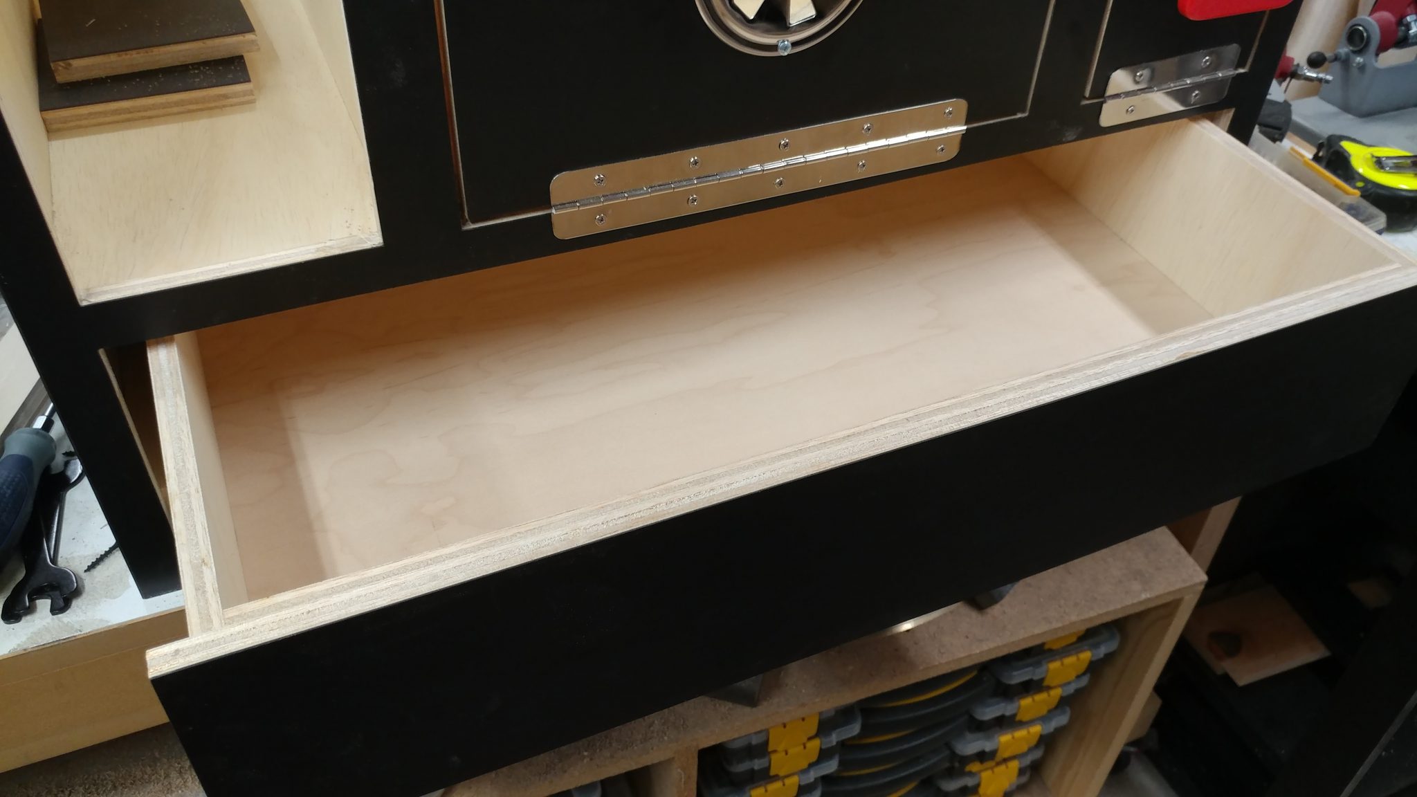
I attached the drawer sections of the glides to the main drawer body.
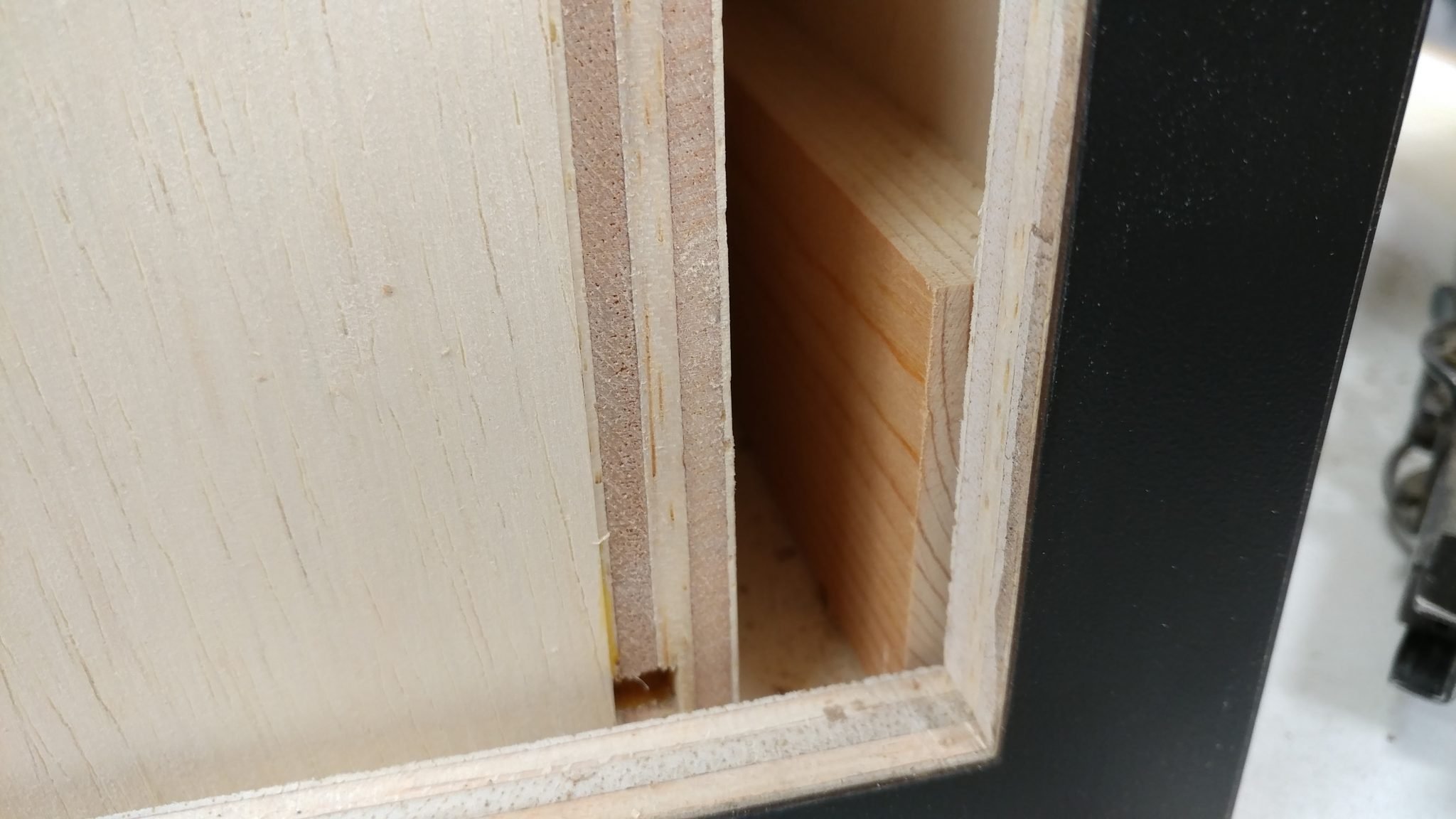
I used a few pieces pieces of plywood as spacers to hold up the cabinet section of the drawer glides and I screwed them into place.
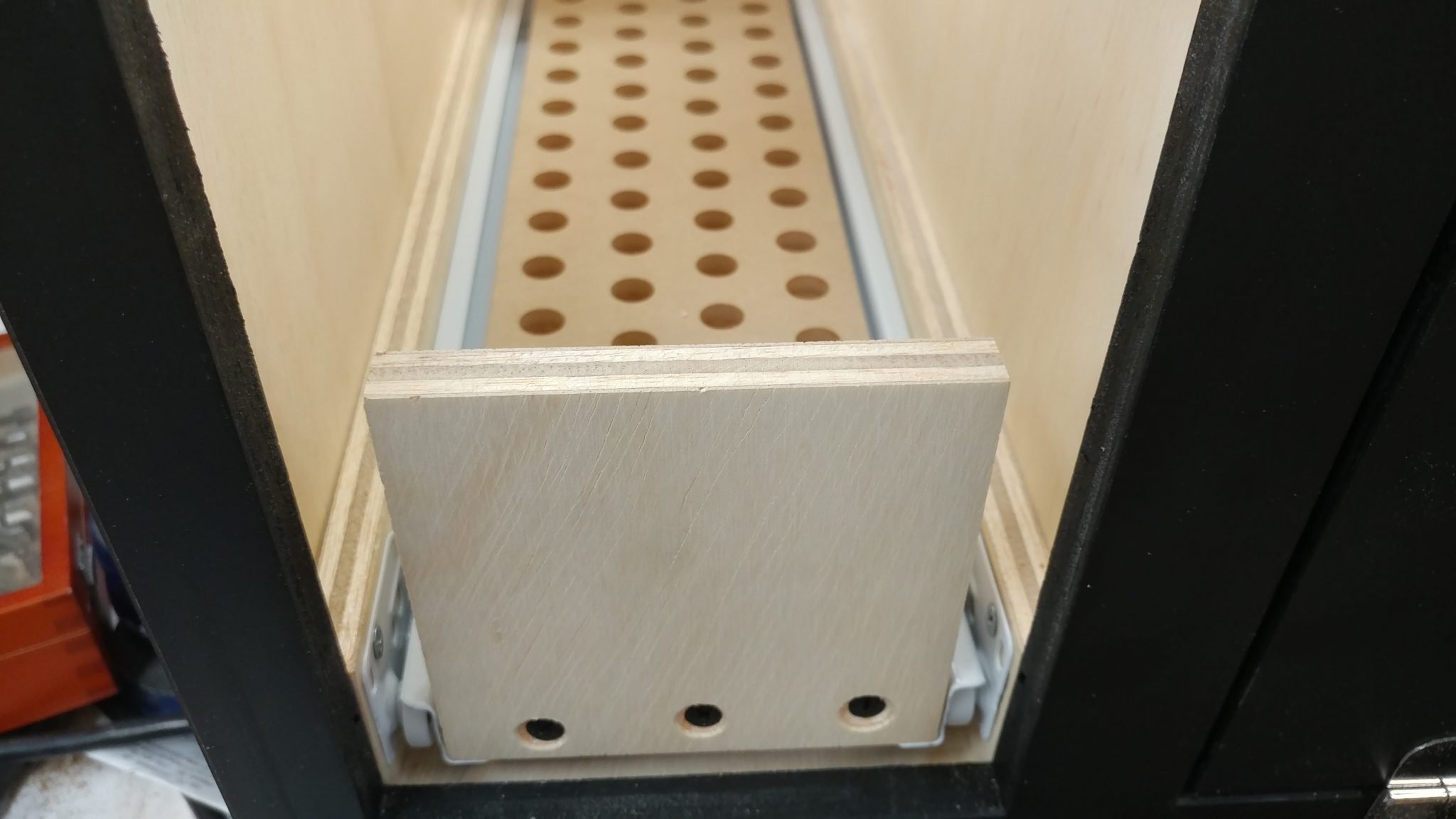
This allowed me to insert the drawer, It’s now ready for the face.

Double-sided tape was attached to the back of the drawer face.
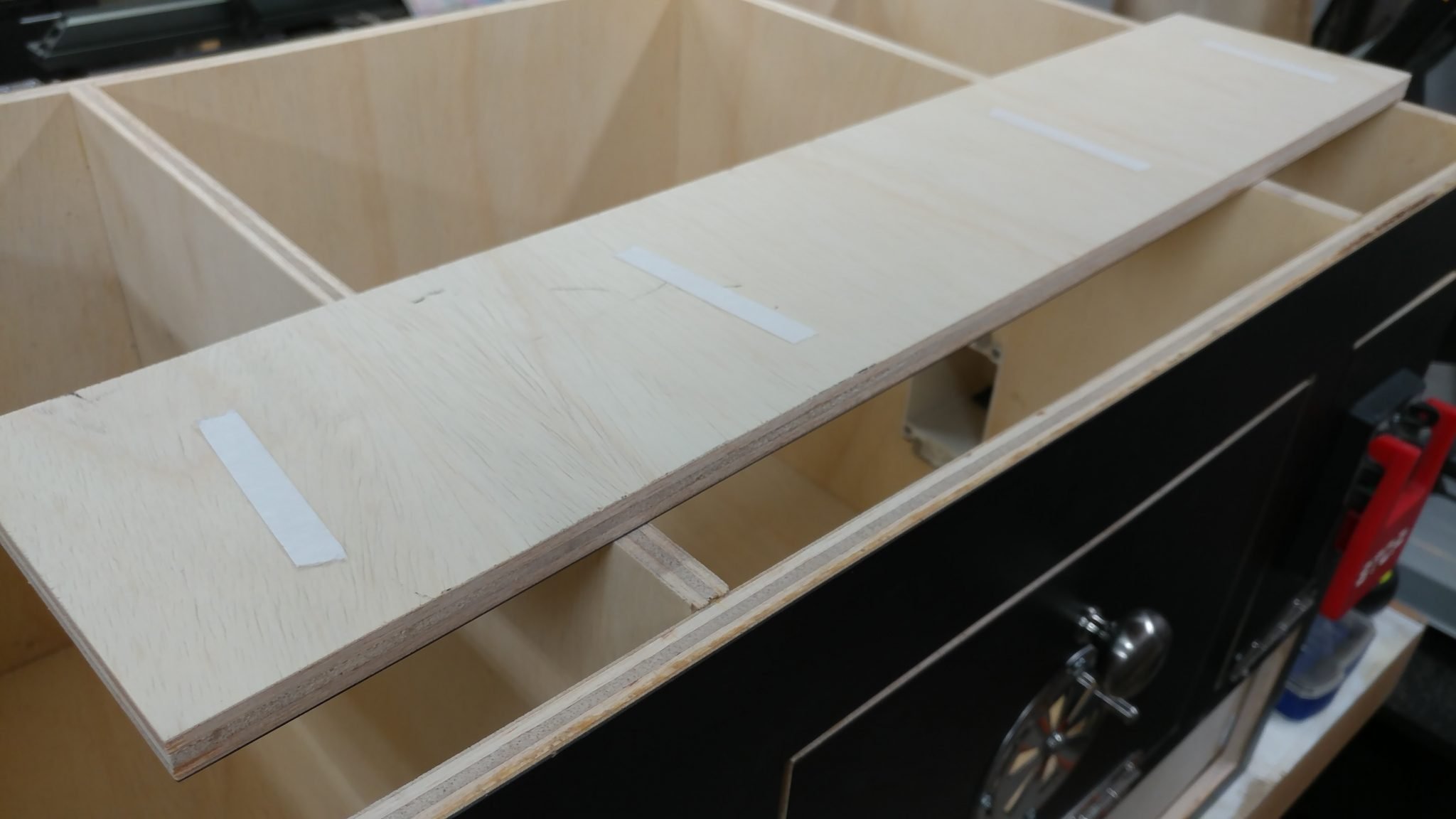
I used the same 1/8″ thick spacers to position the drawer face.
Then I pressed the drawer face onto the drawer body.
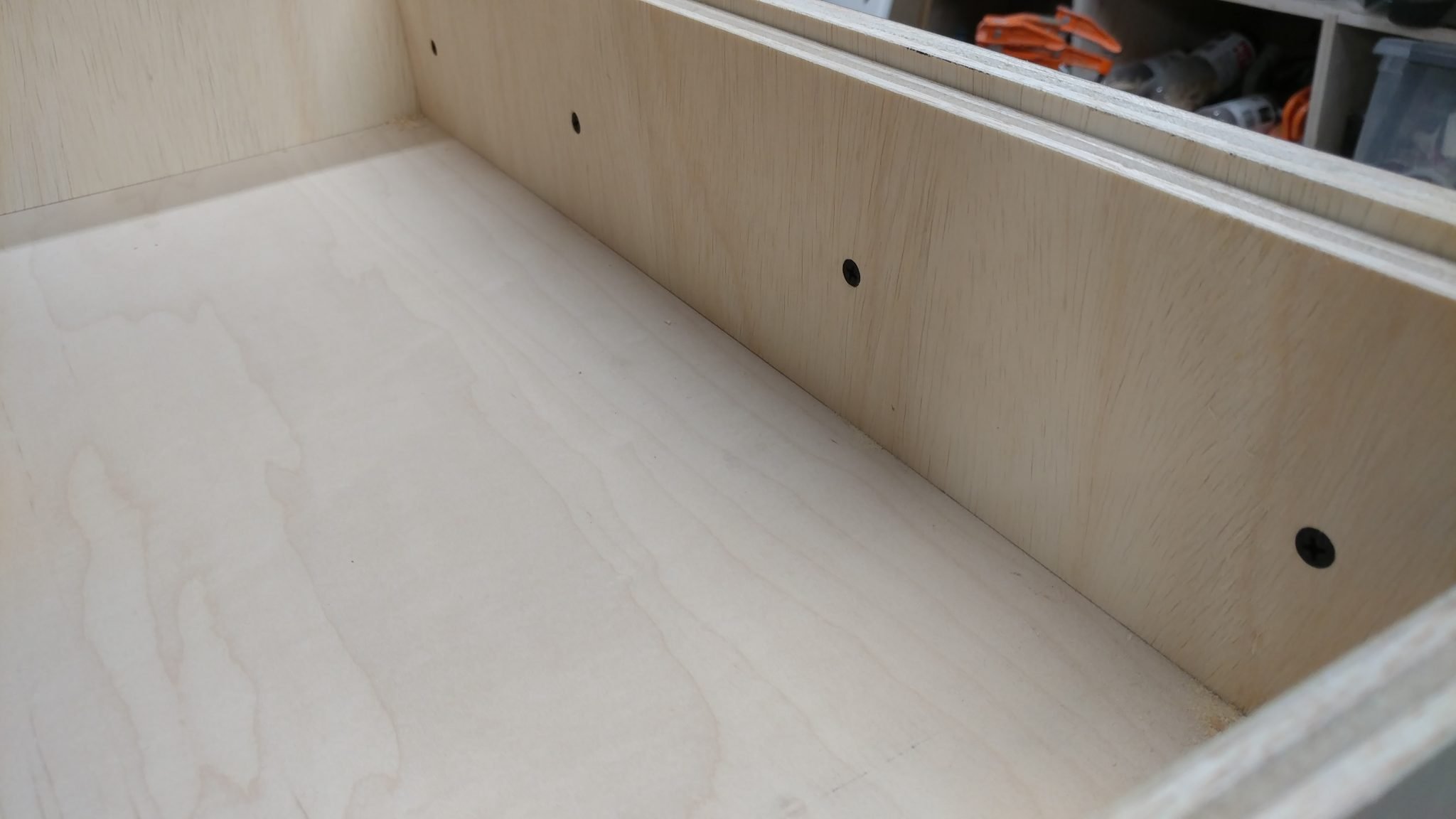
Once that was done, I pulled out the drawer to I could access the inside.
I then secured the face to the drawer with some drywall screws.
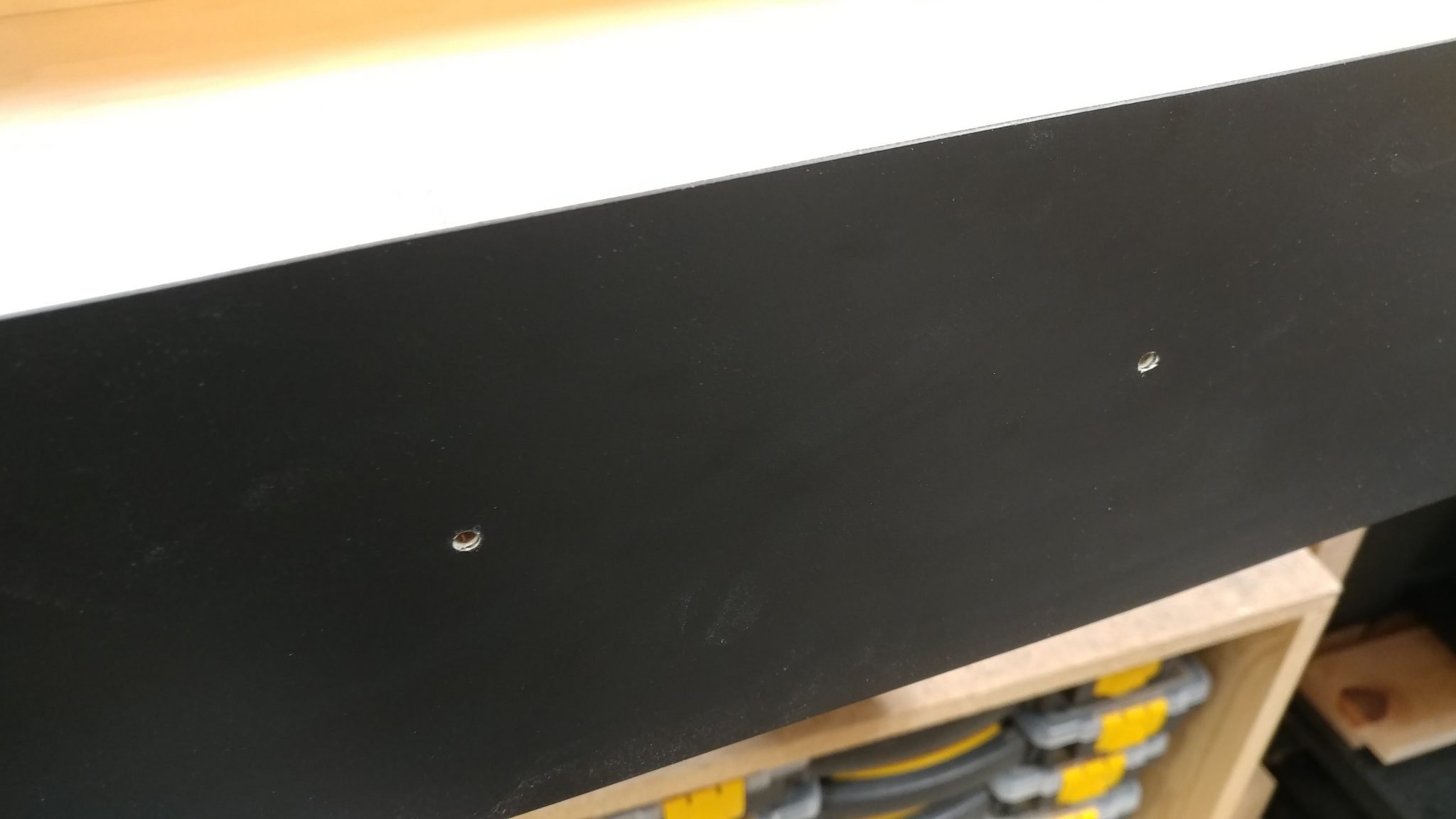
I drilled some holes through the face and the body so I could attach a drawer pull.
The drawer pull was attached and this drawer is complete. I also temporarily attached the electrical paddle. The reason I didn’t install a drawer pull on the electrical door is because I’m not expecting to go into that area very often, if at all, and if I need to, I can just pull the paddle out and it doubles as a handle.
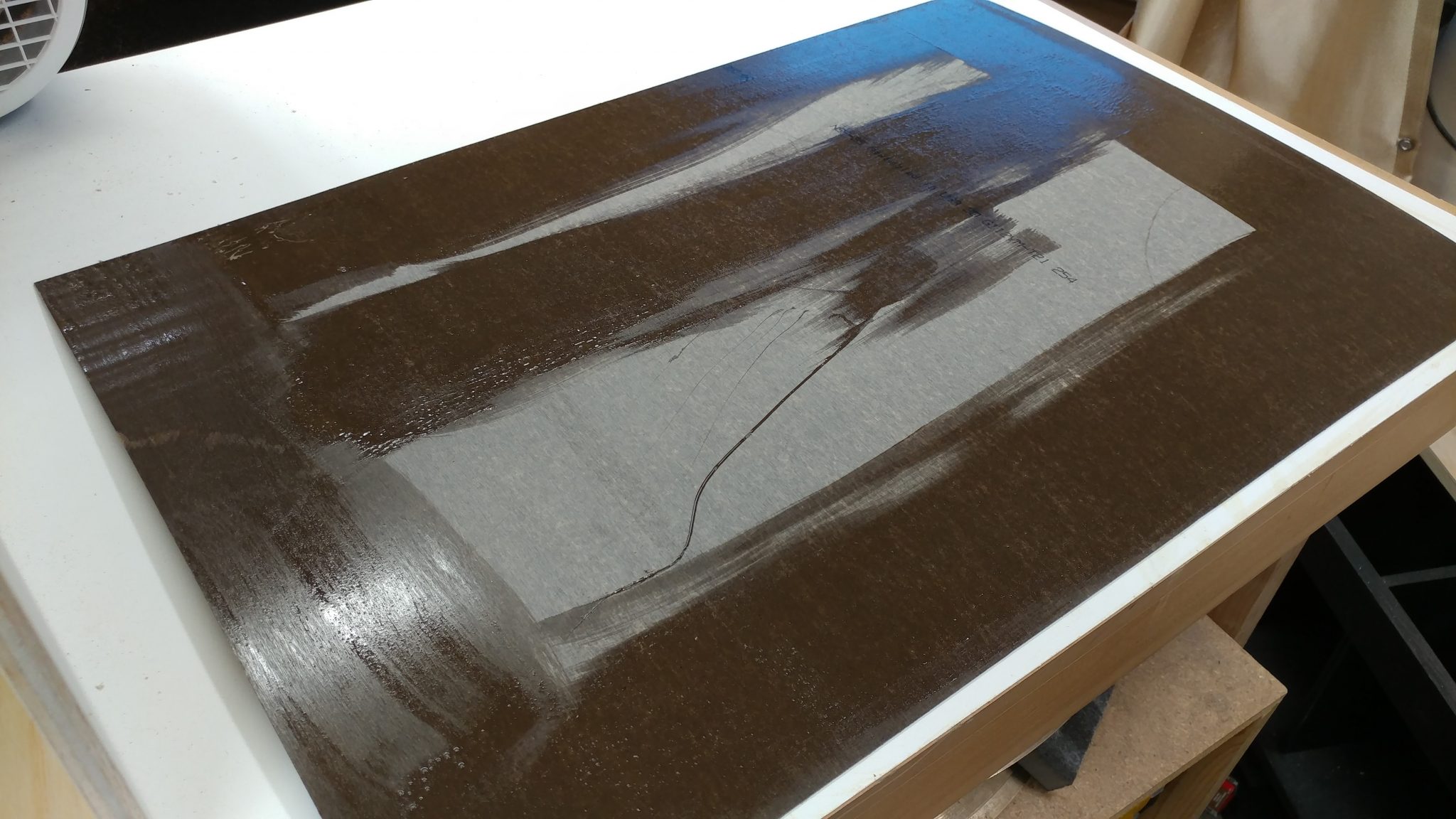
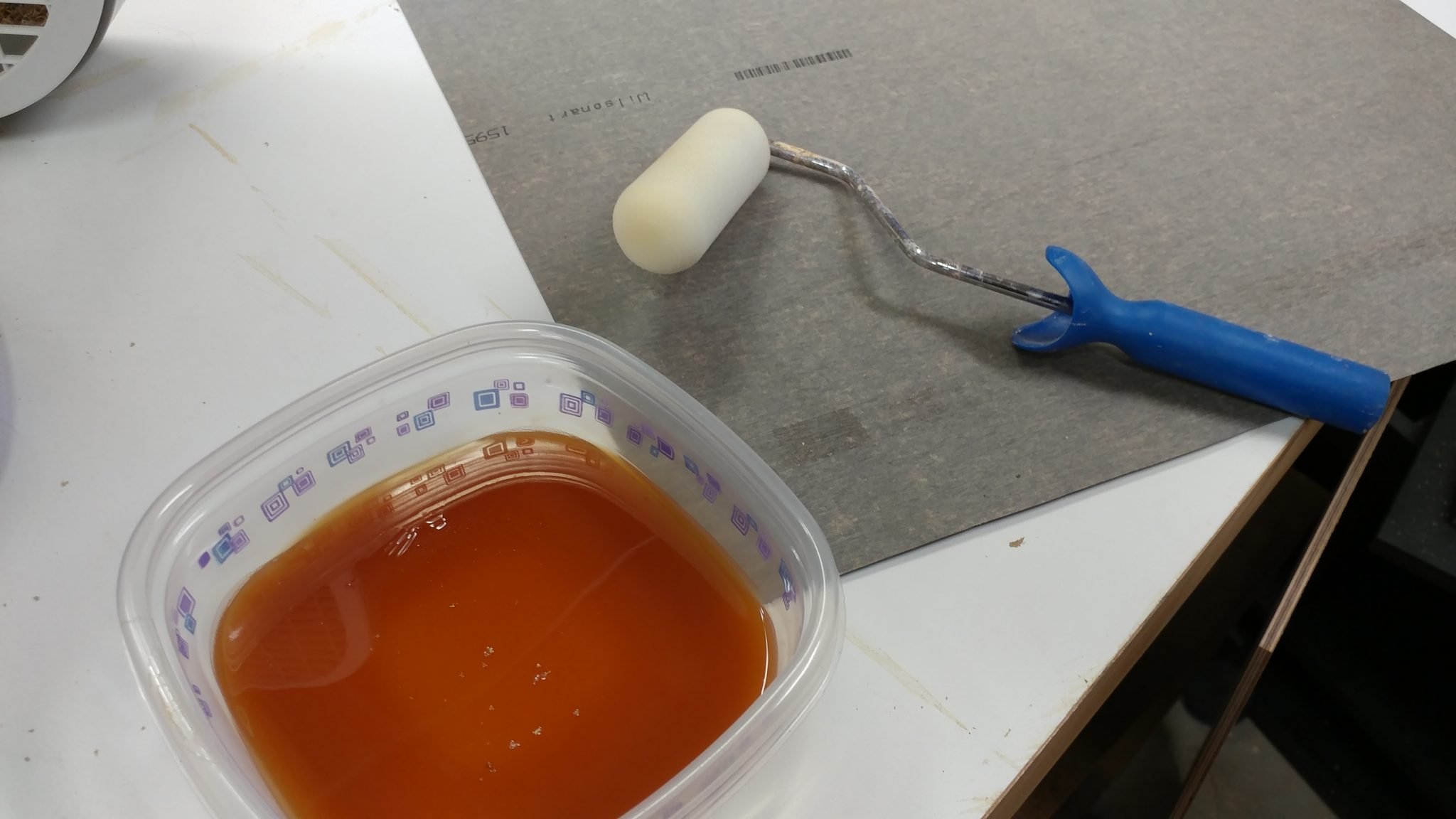
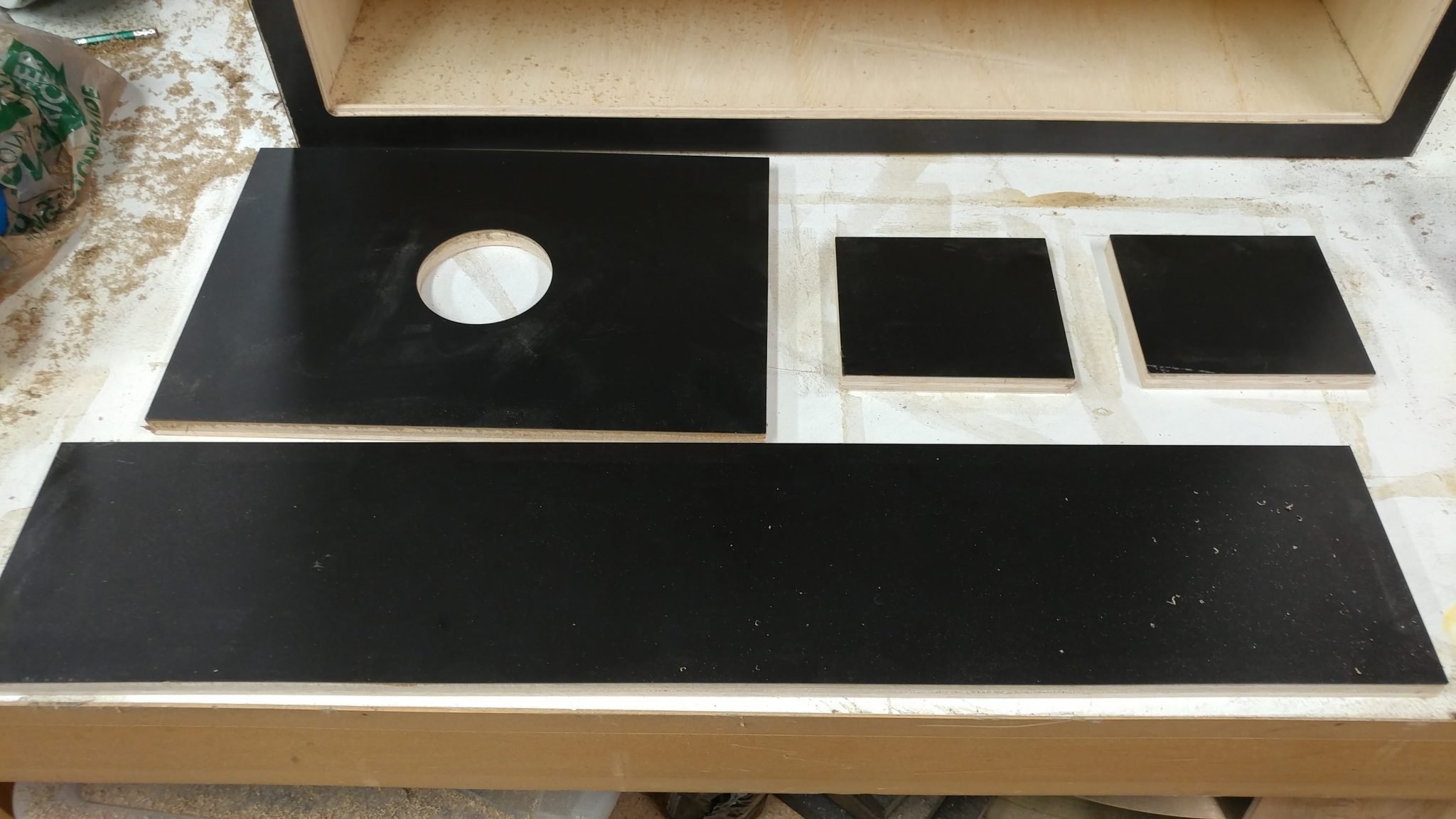
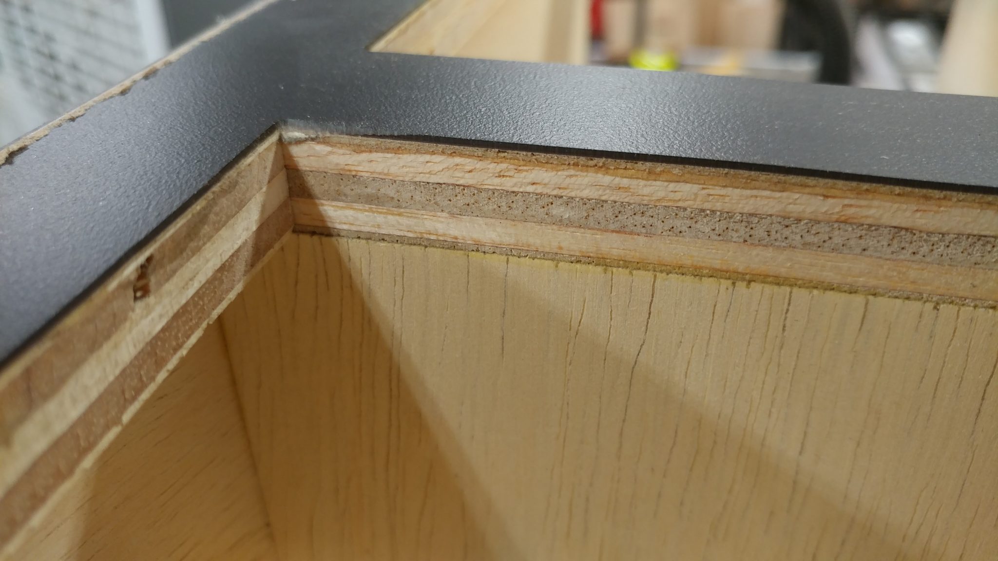
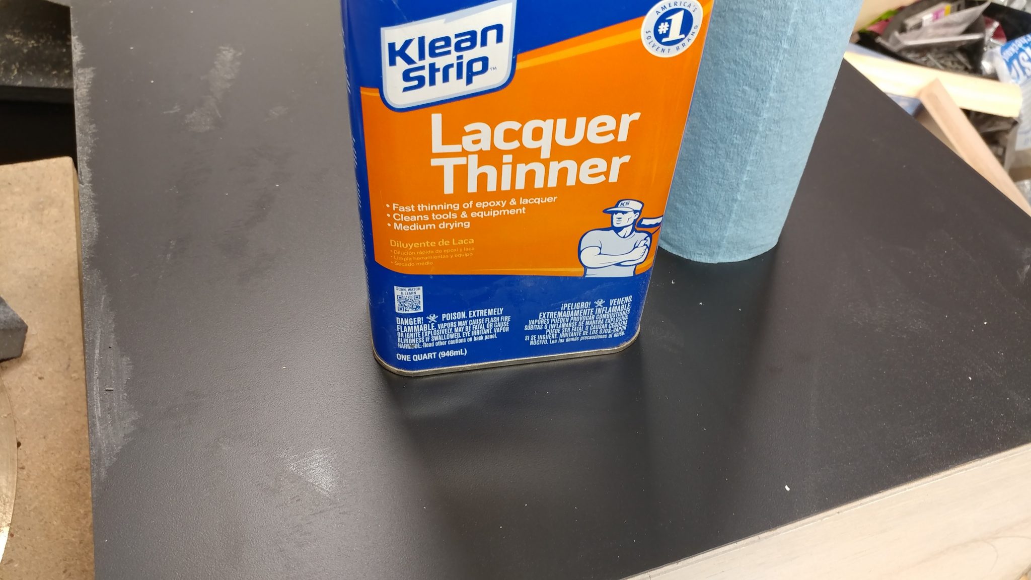
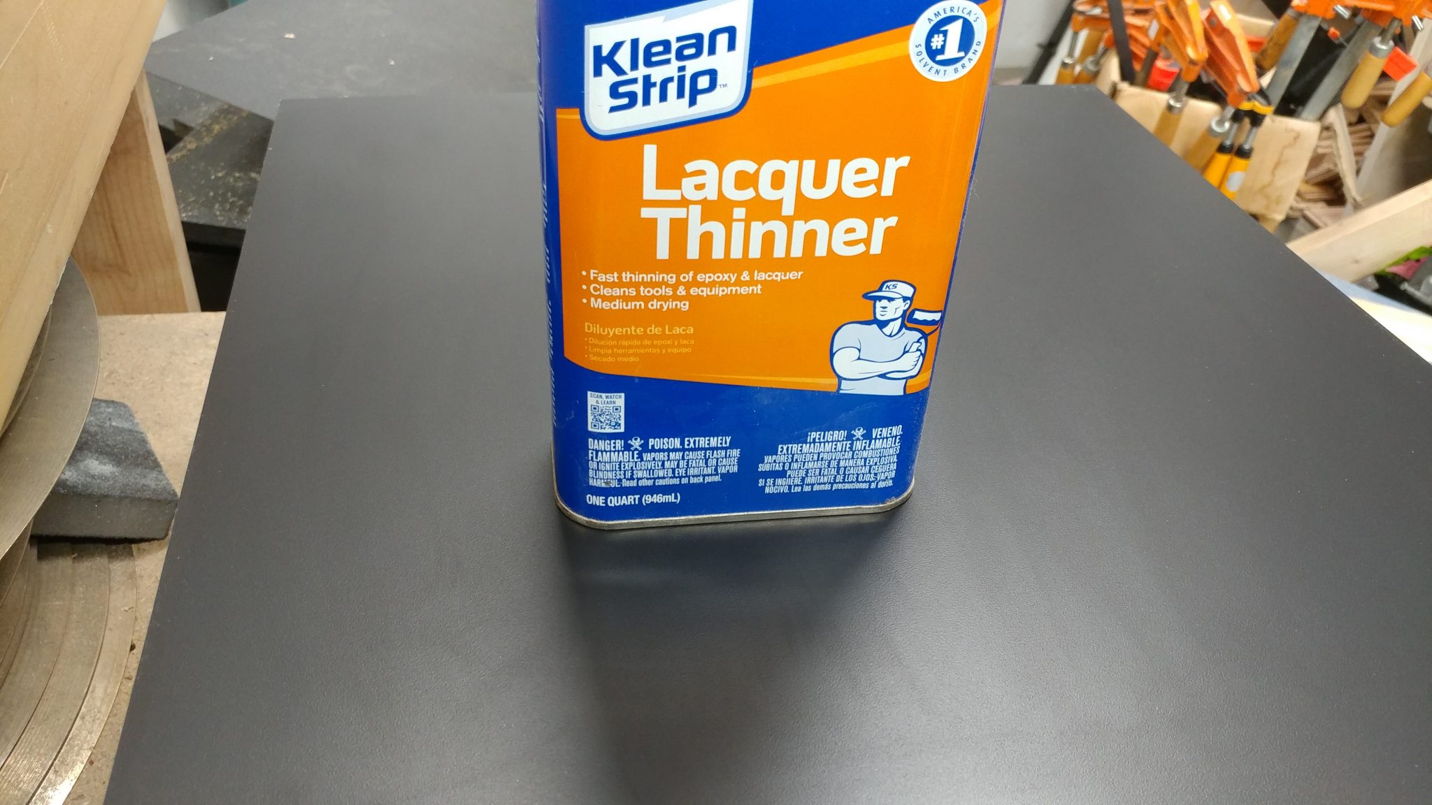
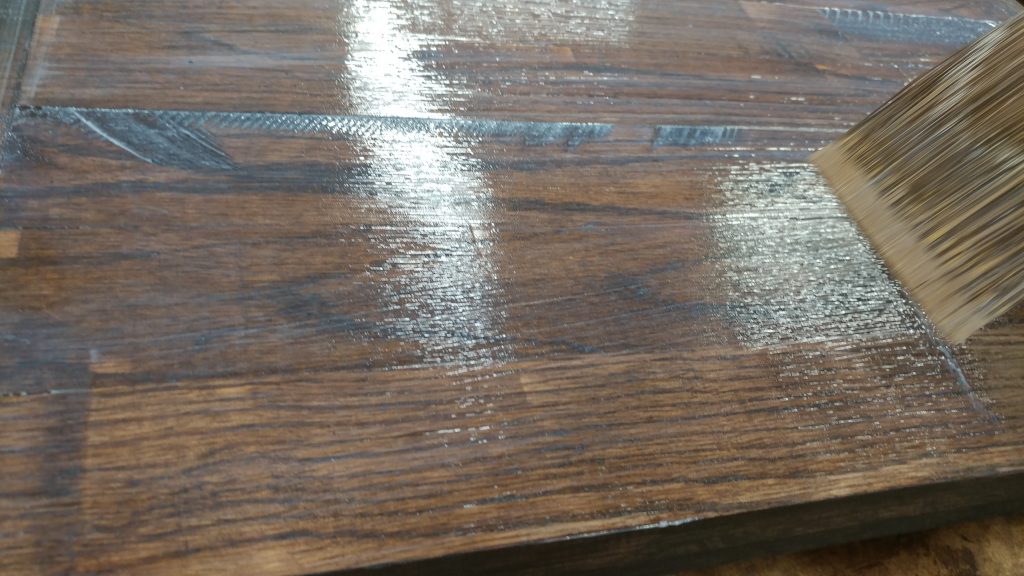
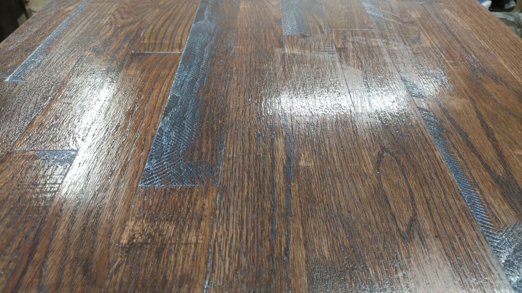
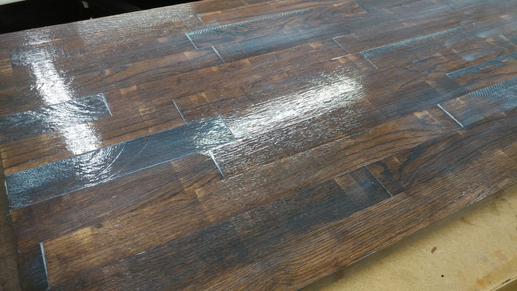
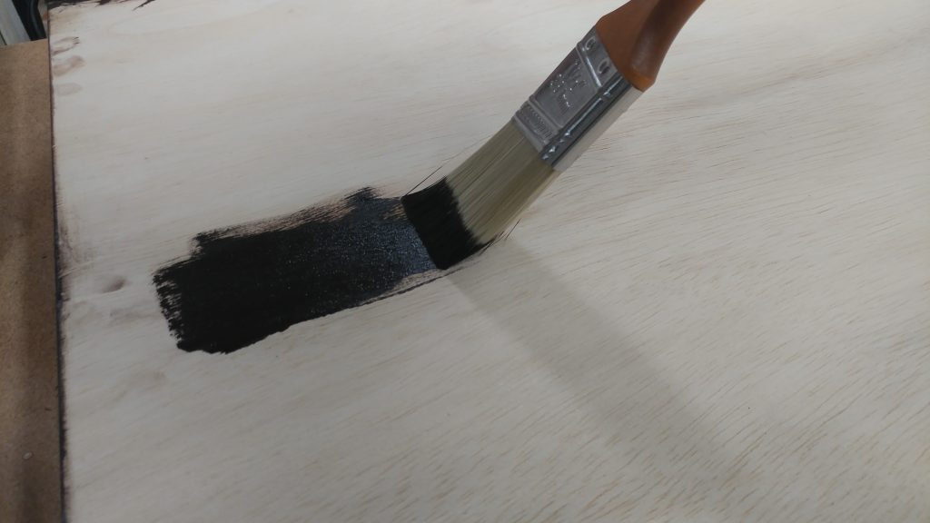
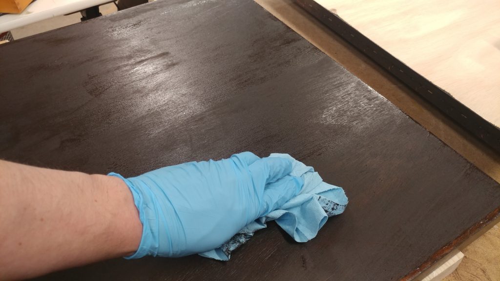
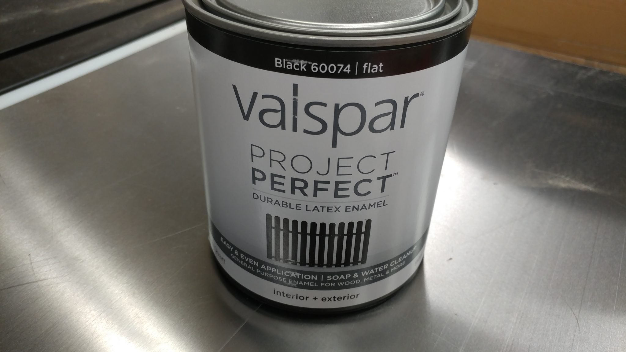
Before finishing up the smaller bit storage drawers, I decided to paint the inner edges of all the openings. For this I used some black Valspar latex enamel.
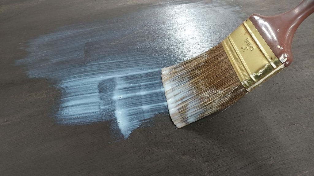
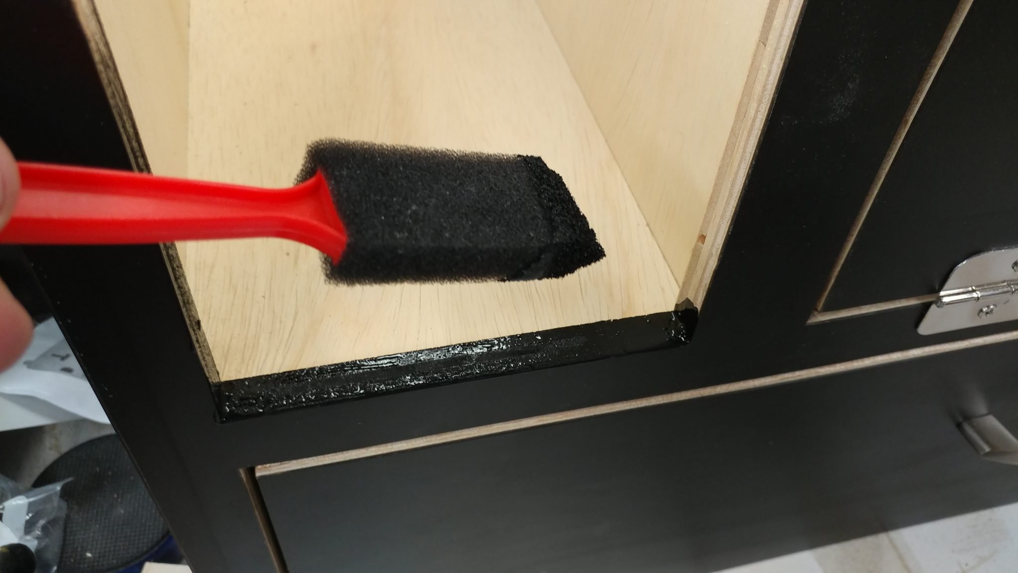
I painted the edges with a cheap foam brush. It doesn’t matter if I get it off the laminate. It’s really easy to remove. I’ll show you how in just a bit.
I removed the doors and the drawer so I could get the edges. The lip that runs along the inside of the doors doesn’t need to be full covered since it will be covered with weather stripping later.
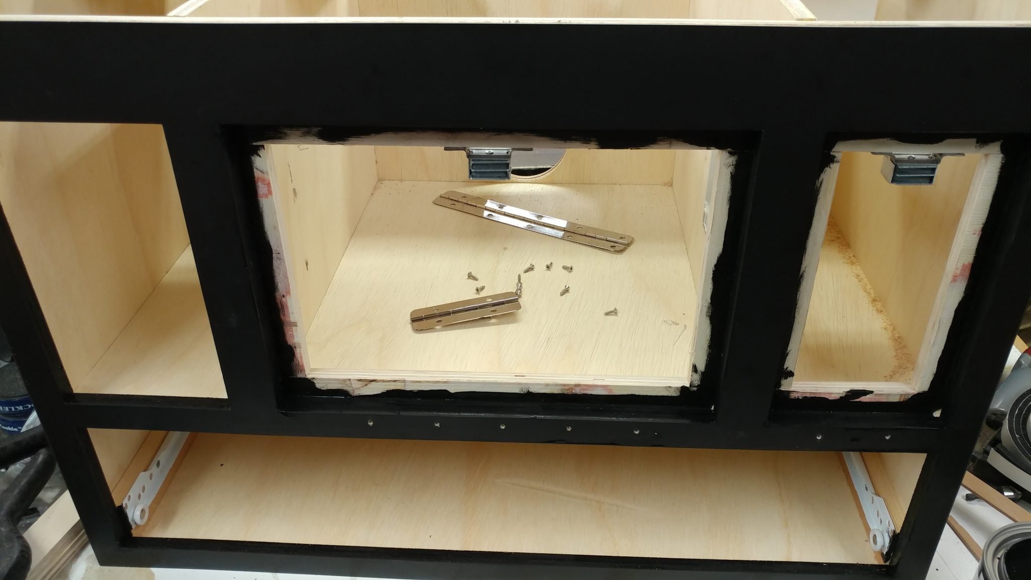
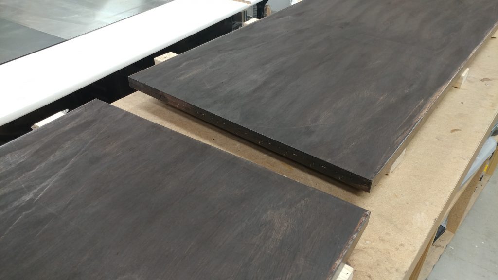
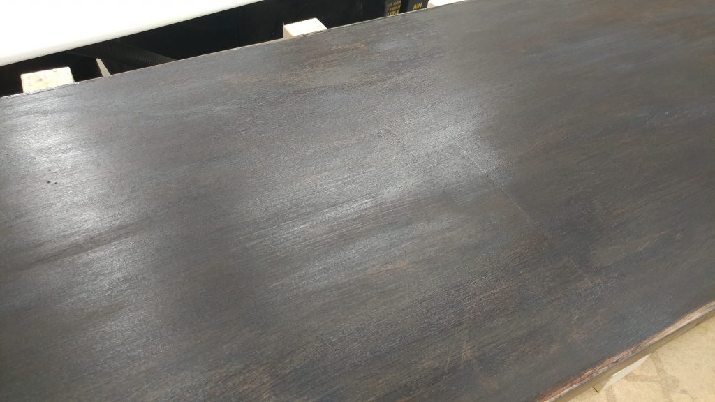
I also painted the edges of the doors and the face of the drawer.
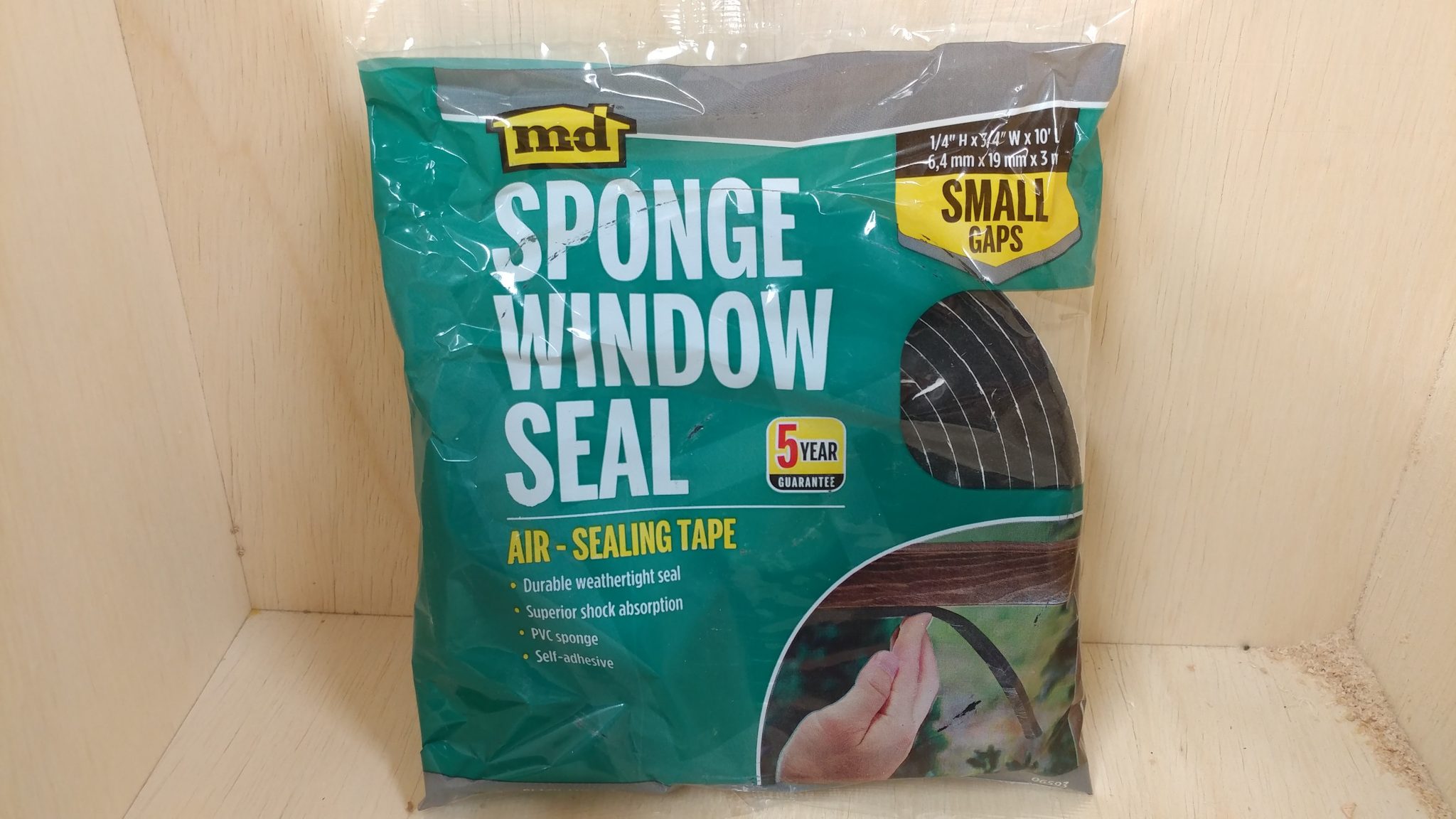
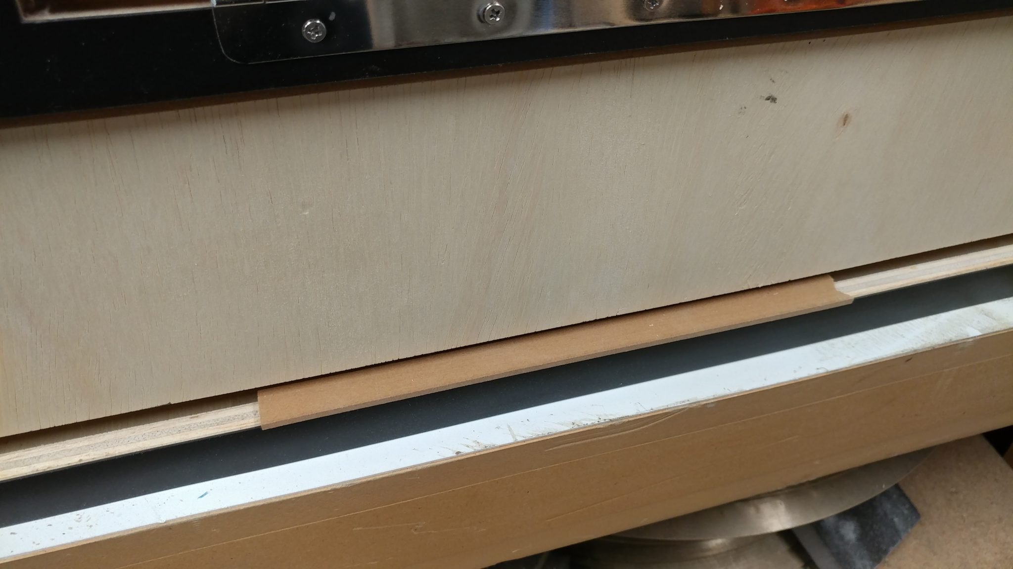
It’s finally time to attach the weather stripping. I cut pieces to size and attached them to the door lip.
After removing the backing tape, you can see that it makes a nice black barrier that should regulate the airflow in the cabinet.
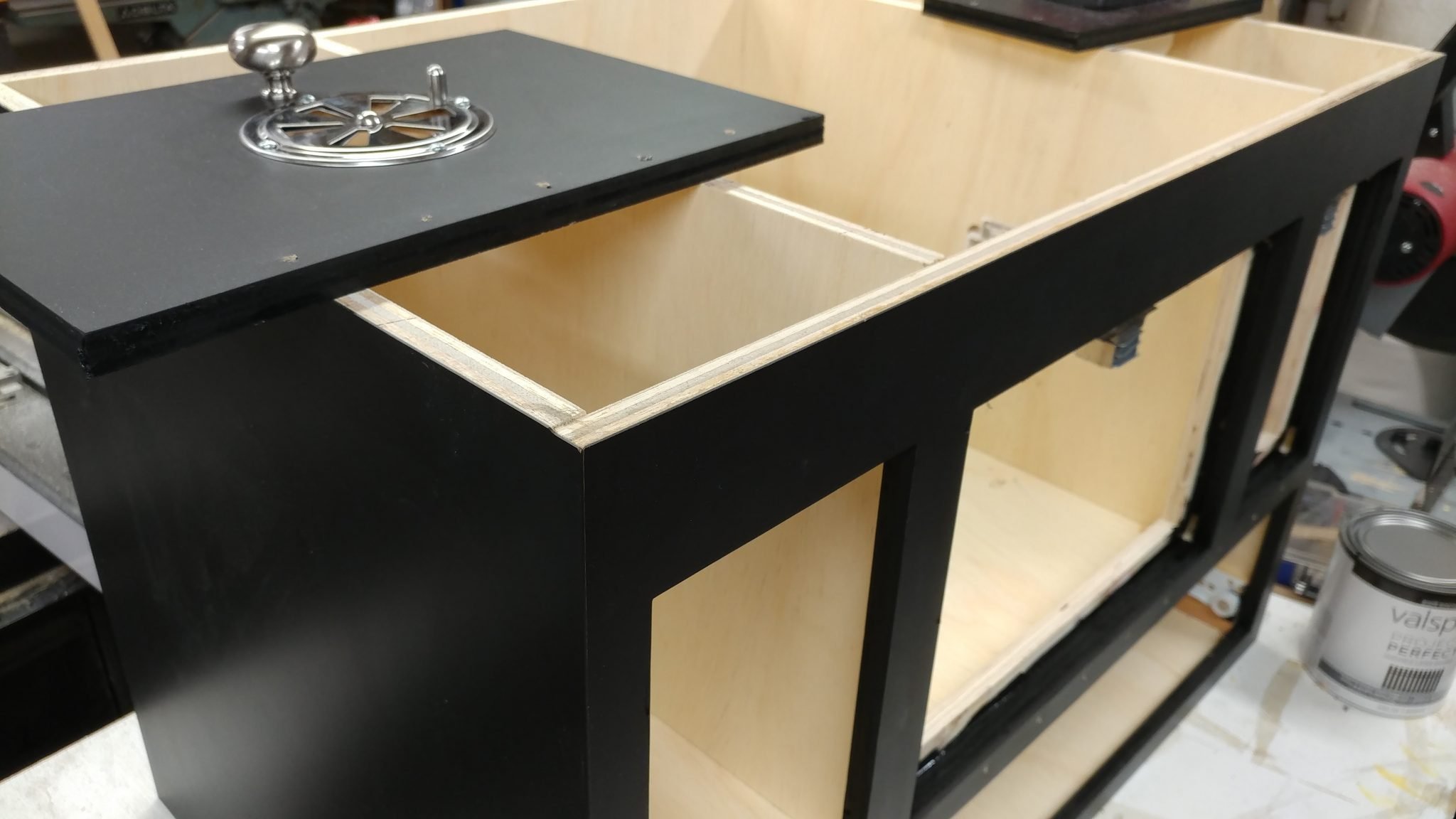
I could then reattach the doors and the drawer. With the edges painted, it has a nice finished look.
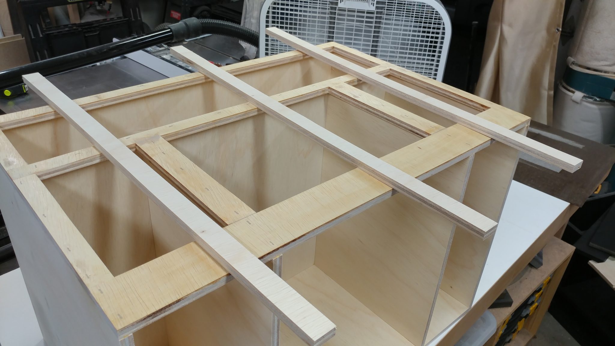
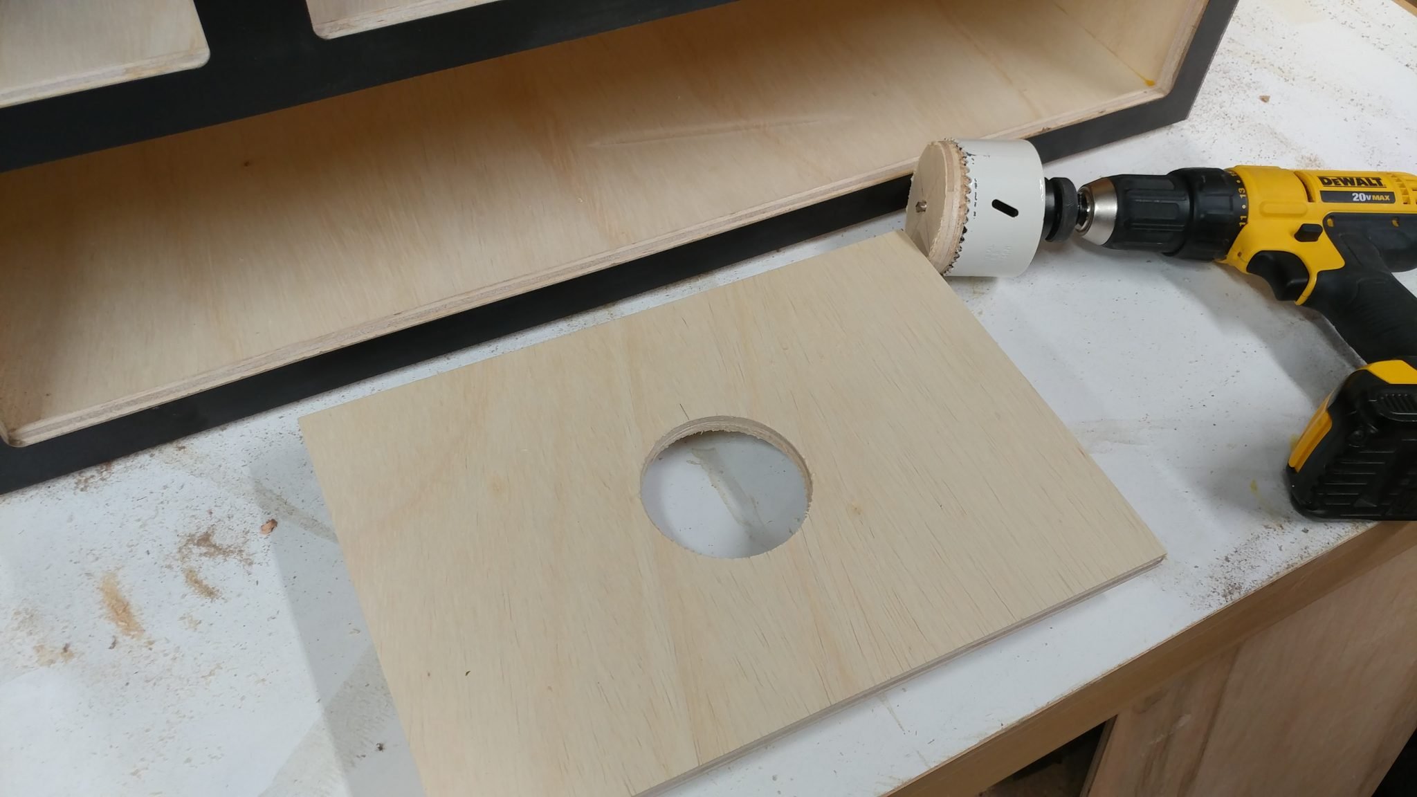
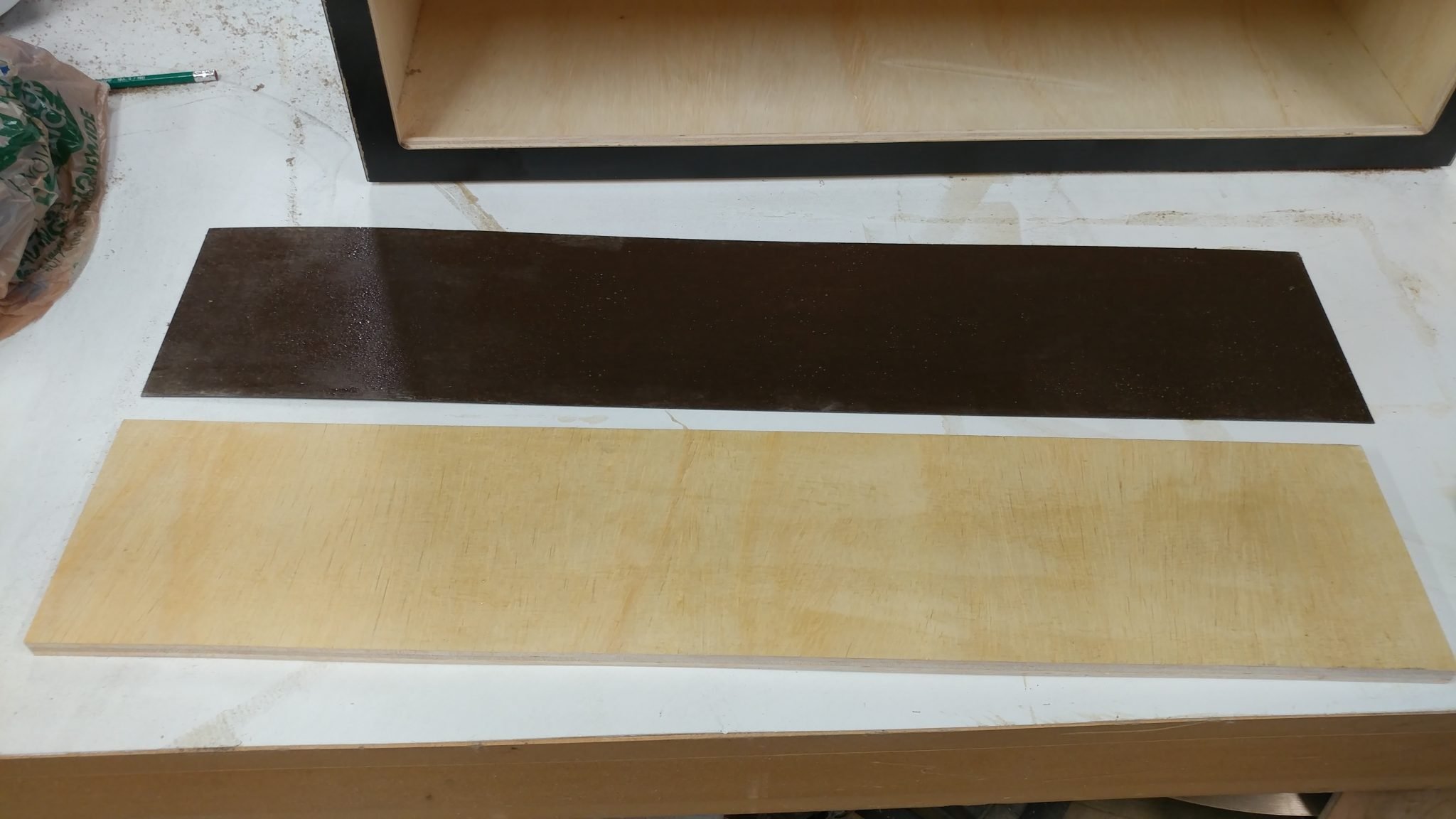
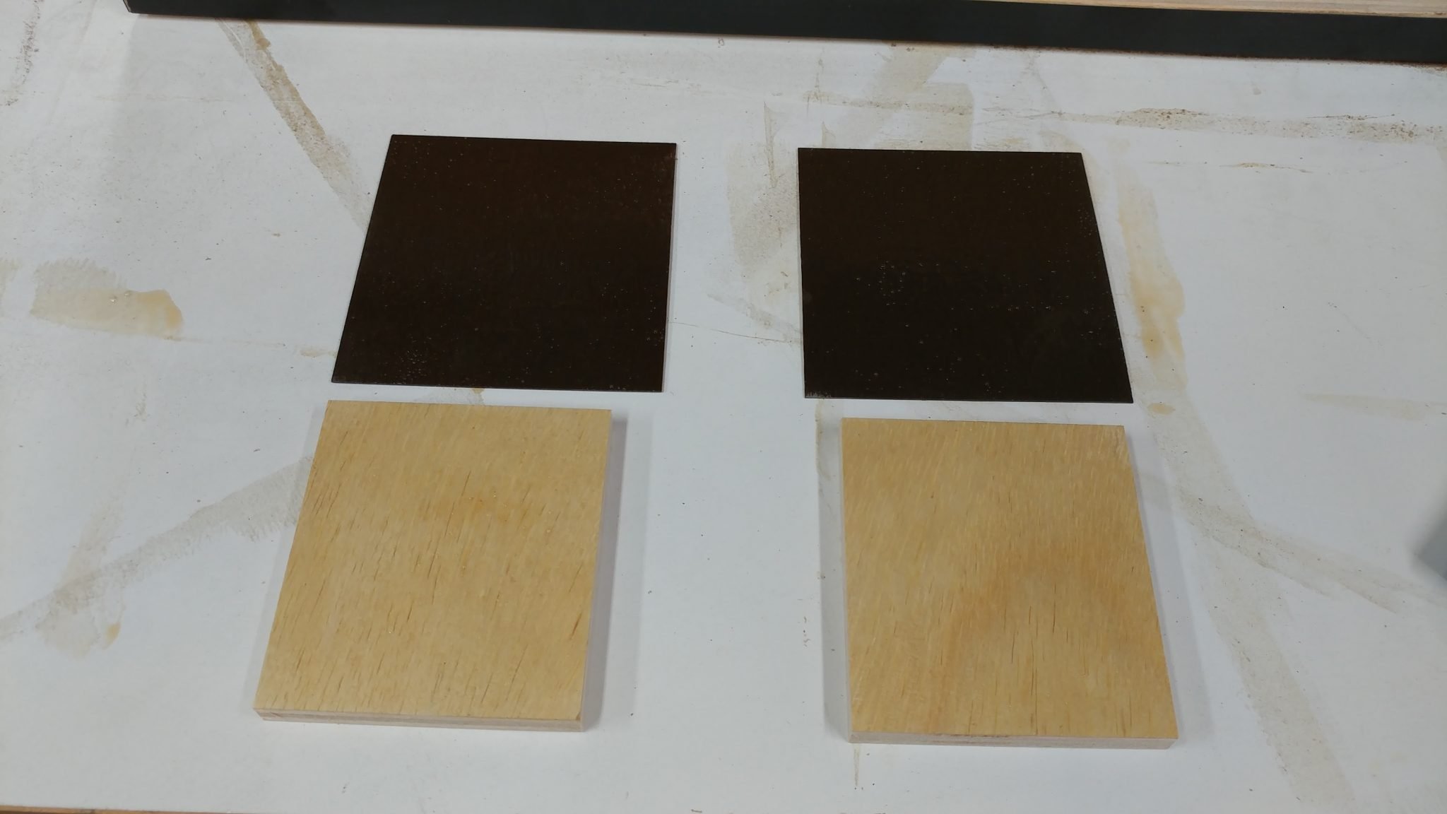
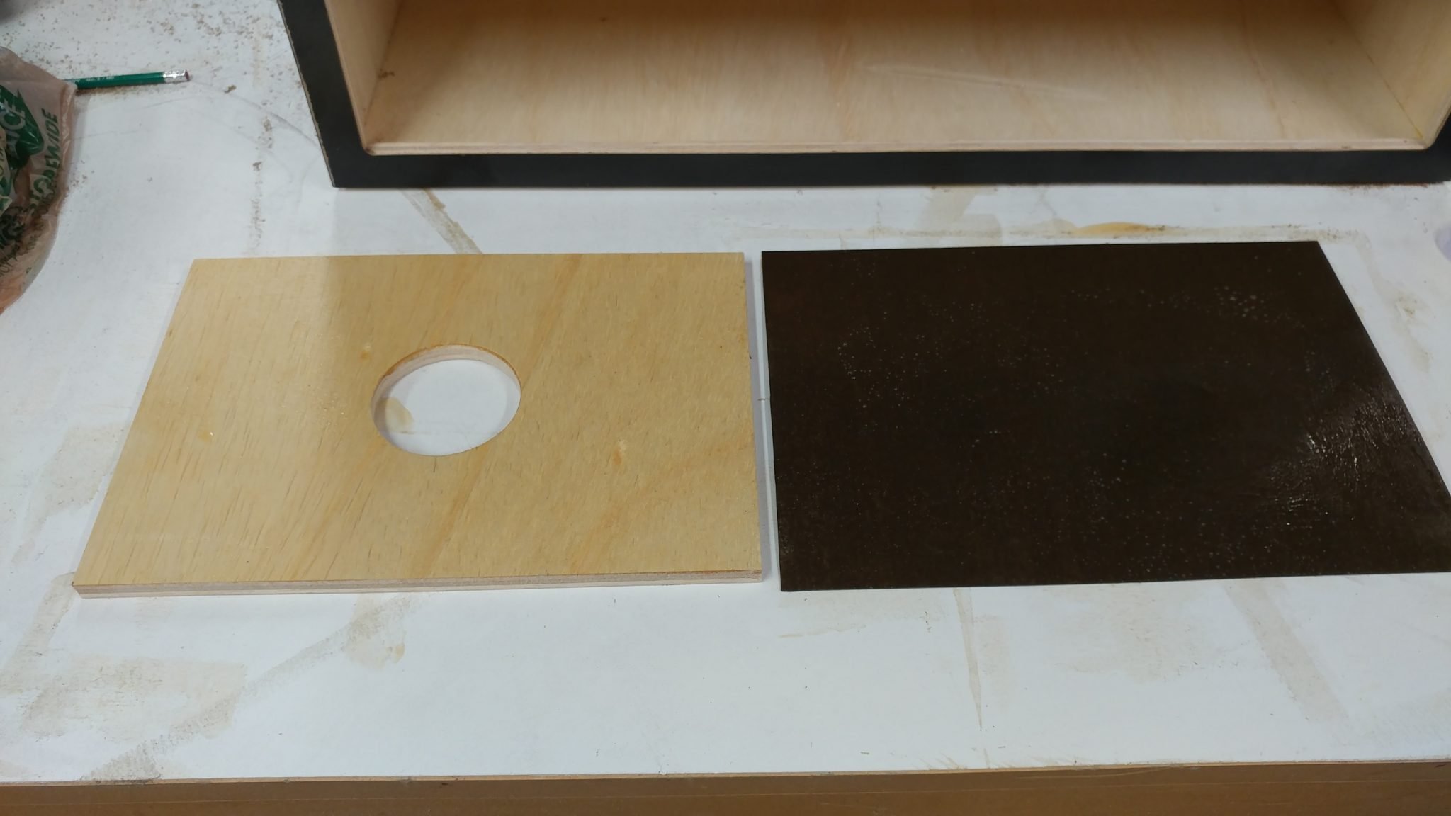
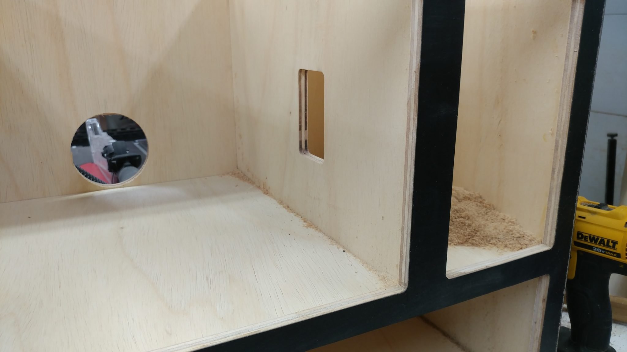
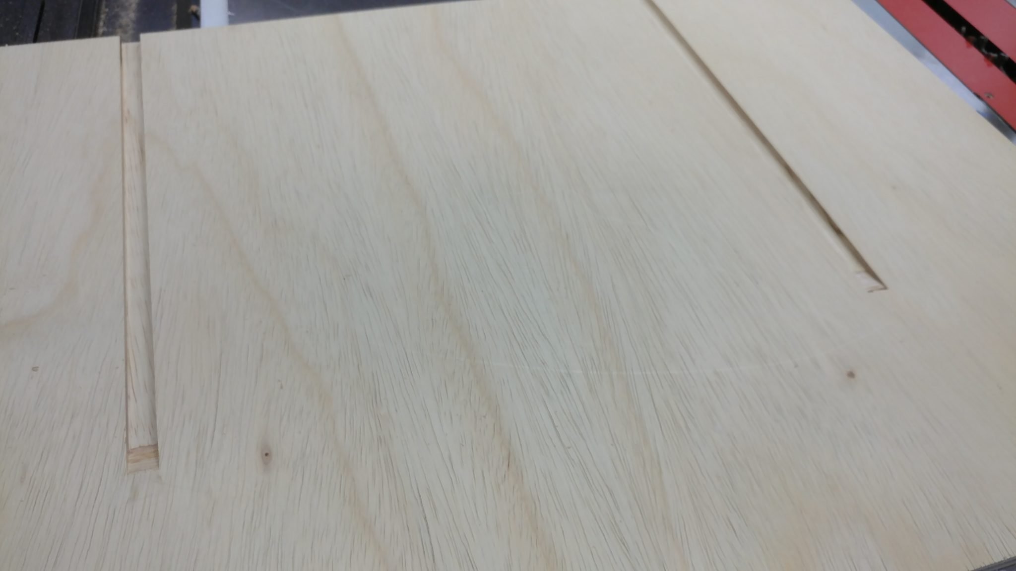
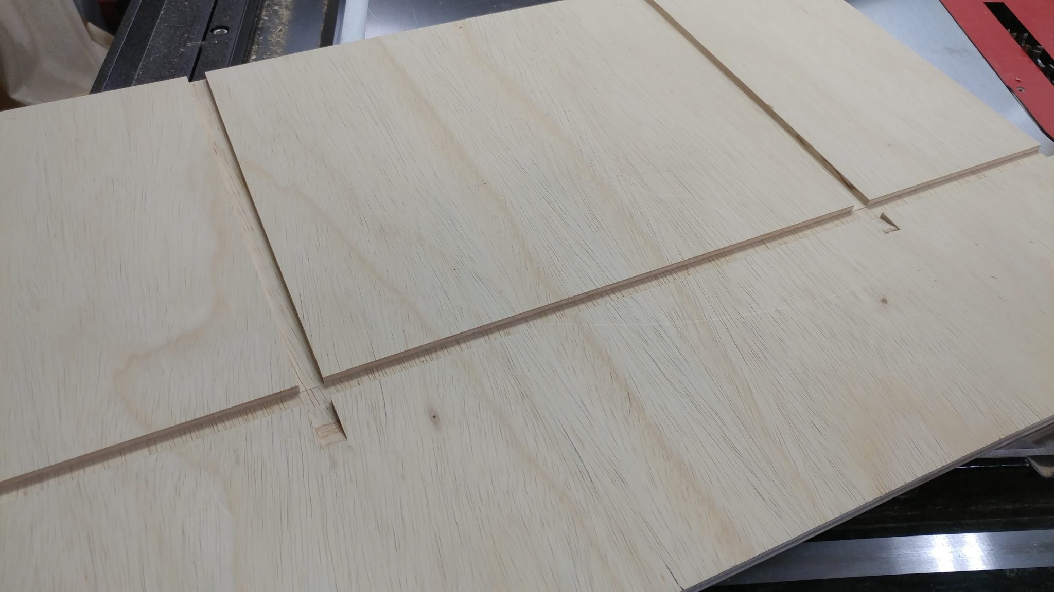
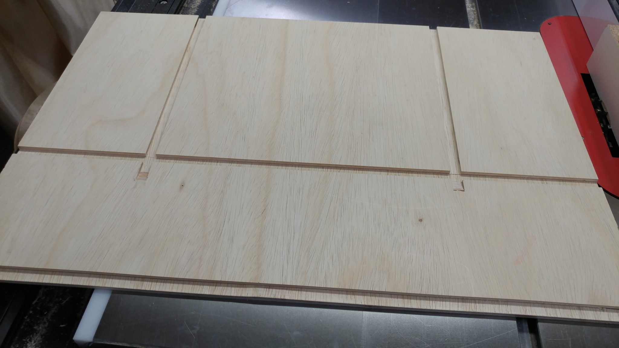
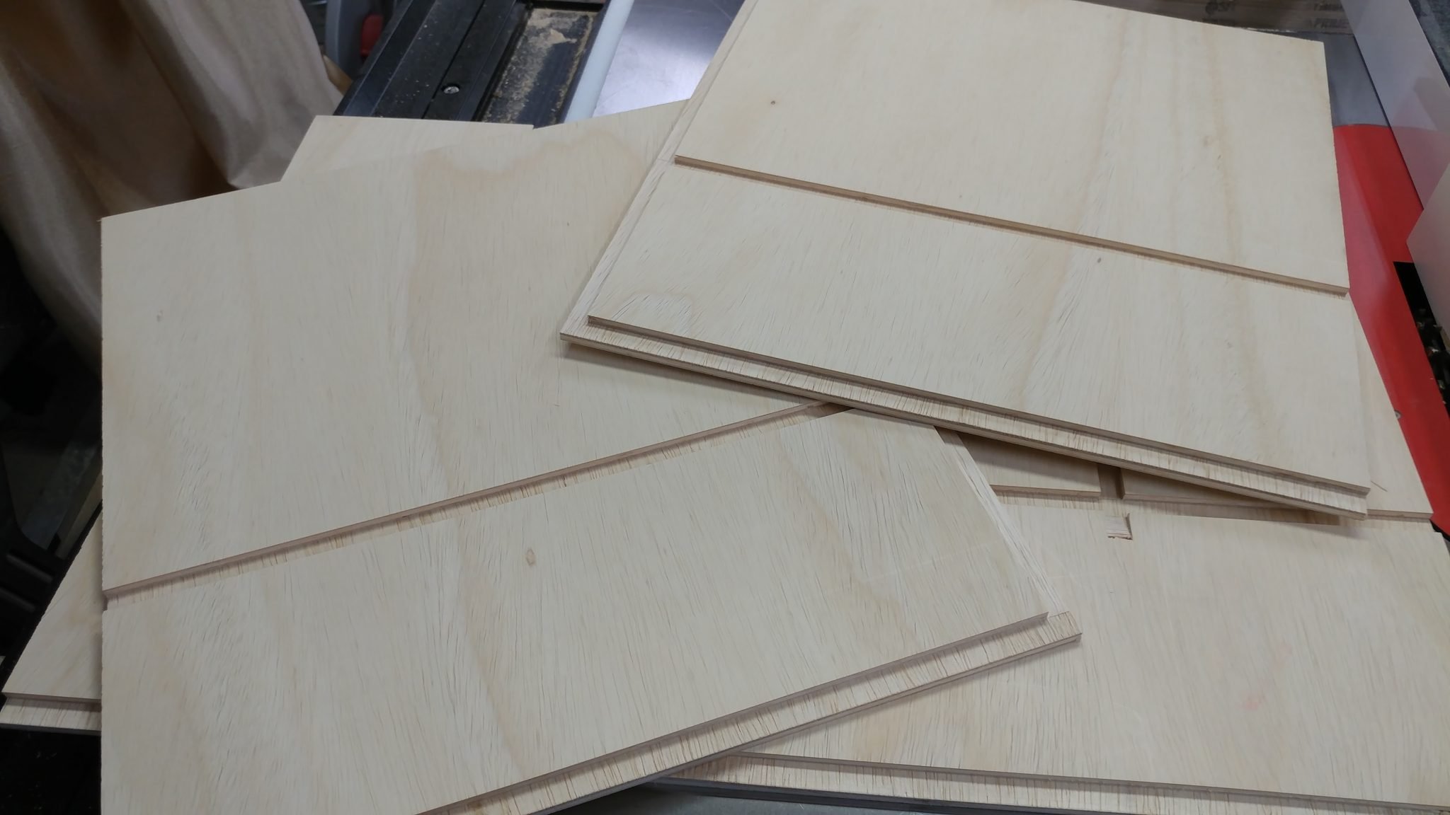
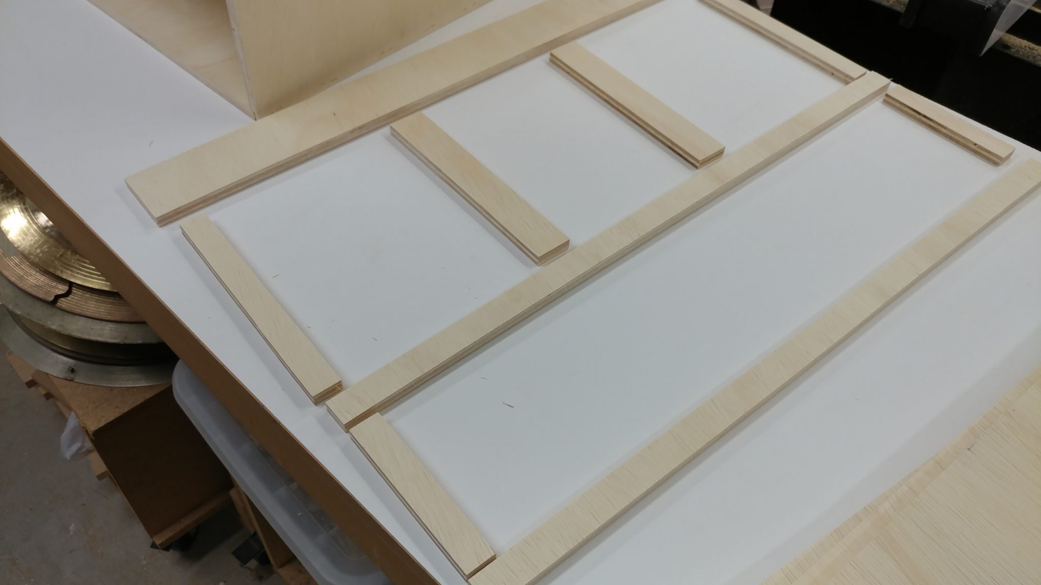
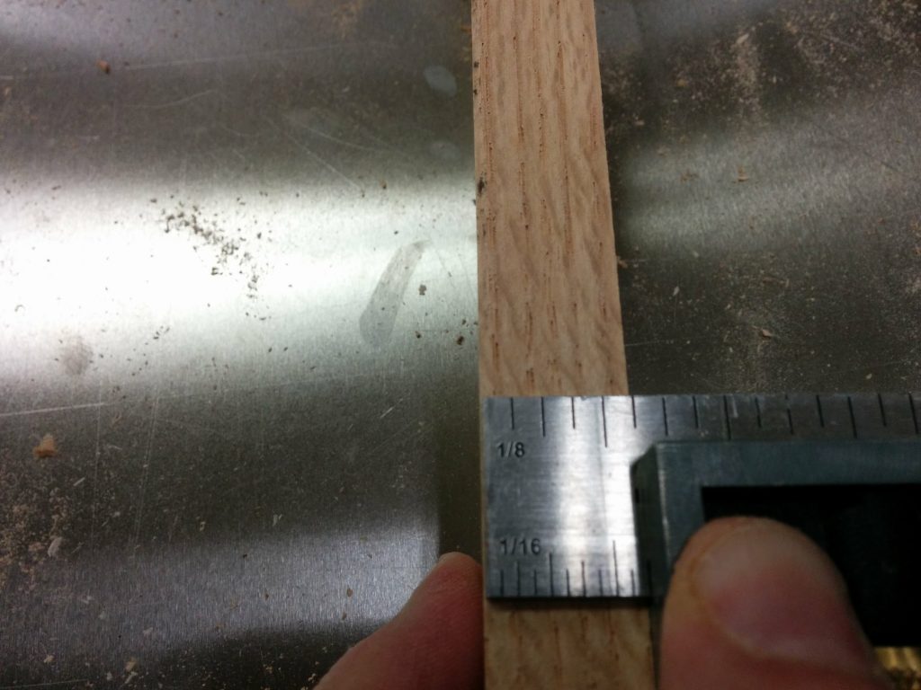
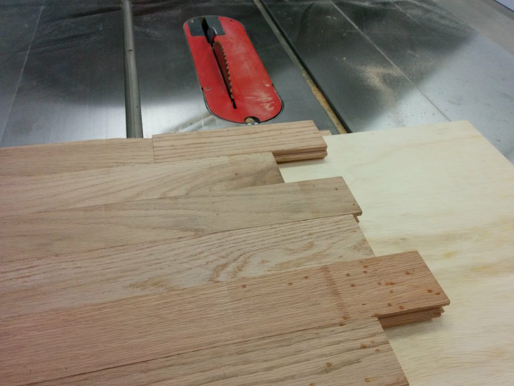
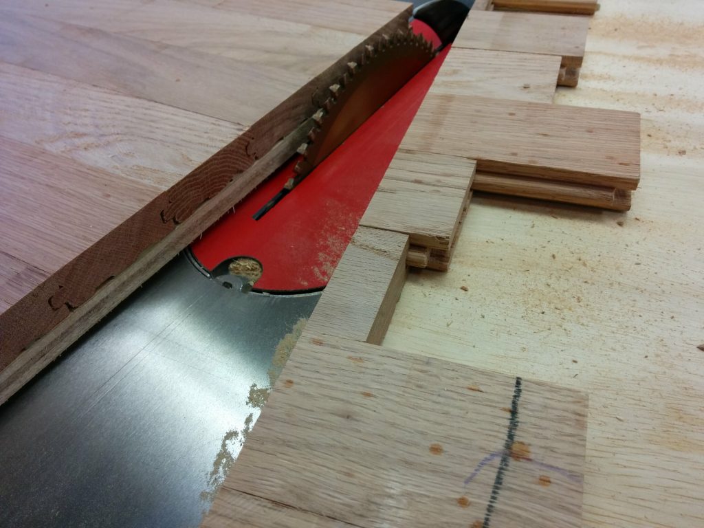
To attach the drawer glides for the bit storage drawers, I cut some 1/2″ plywood into strips.
These were then attached to the inside of the cabinet opening.
The drawer glides were attached…
…and one of the drawers was inserted.
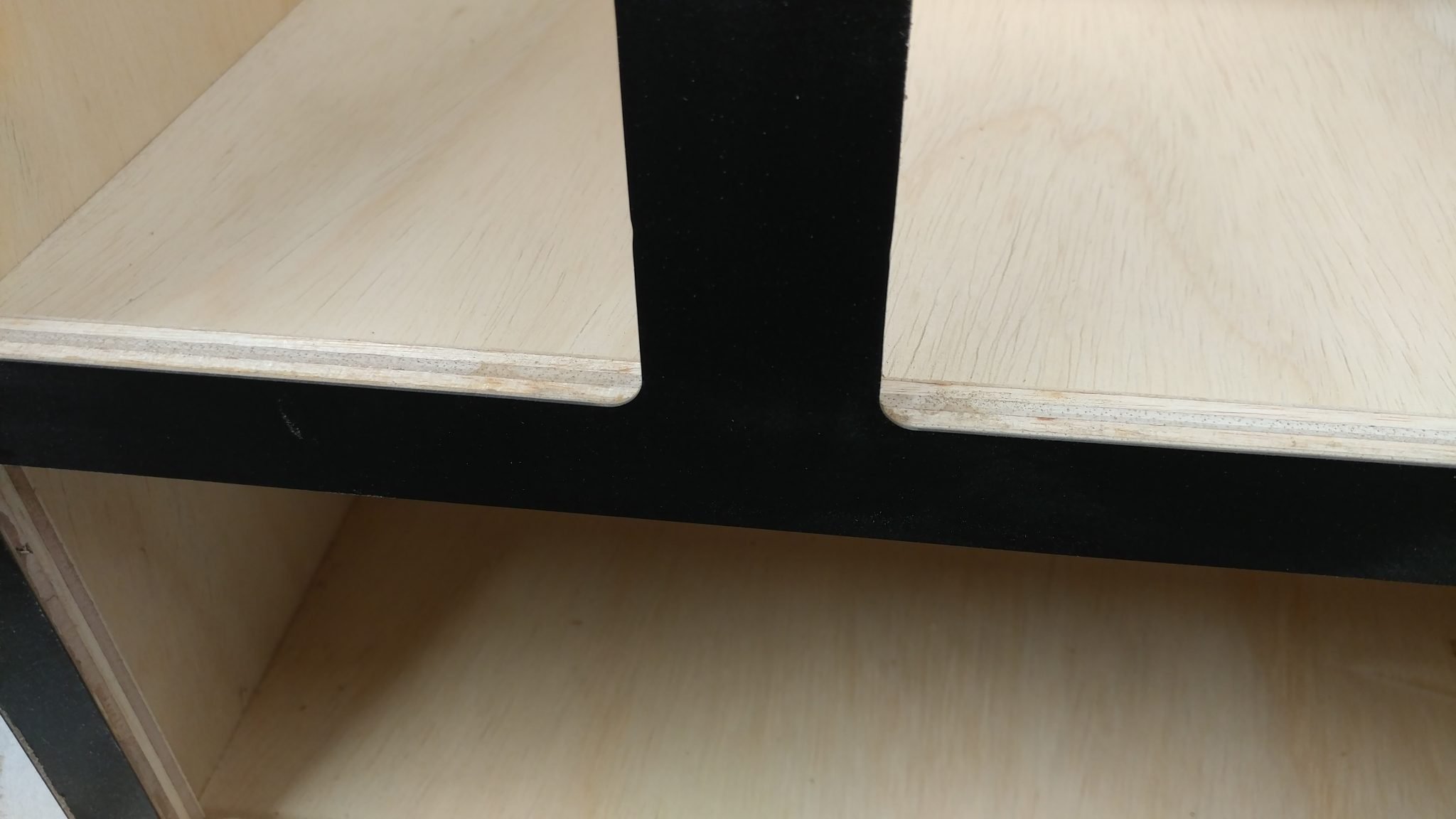
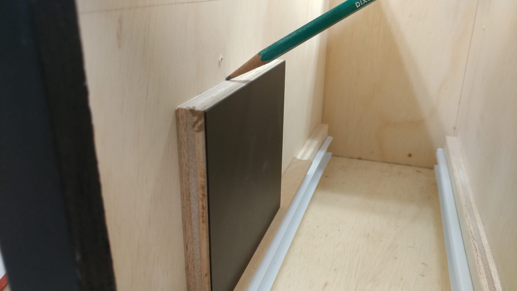
I used the drawer face and a few 1/8″ spacers to mark where the top of the upper strips should be mounted.
The strips were glued and screwed like the others.
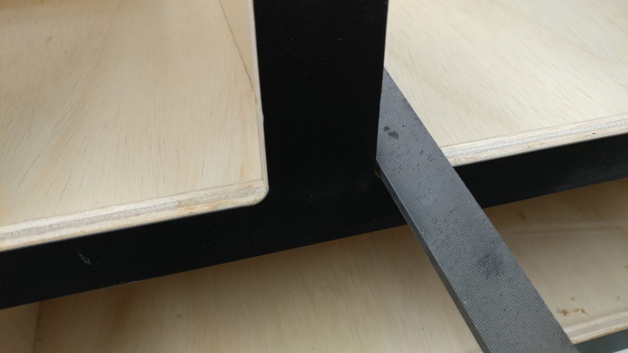
To position where I wanted the drawer glides, I used a combination of a piece of 1/2″ plywood plus a 1/8″ spacer – which is how I positioned the lower glide – pluse two more 1/8″ spacers and the faceplate for one of the drawers.
The drawers are now in position.
I attached the faces the same way that I did for the bigger drawer. First I attached some double-sided tape…
…and attached it using some 1/8″ spacers on the edges.
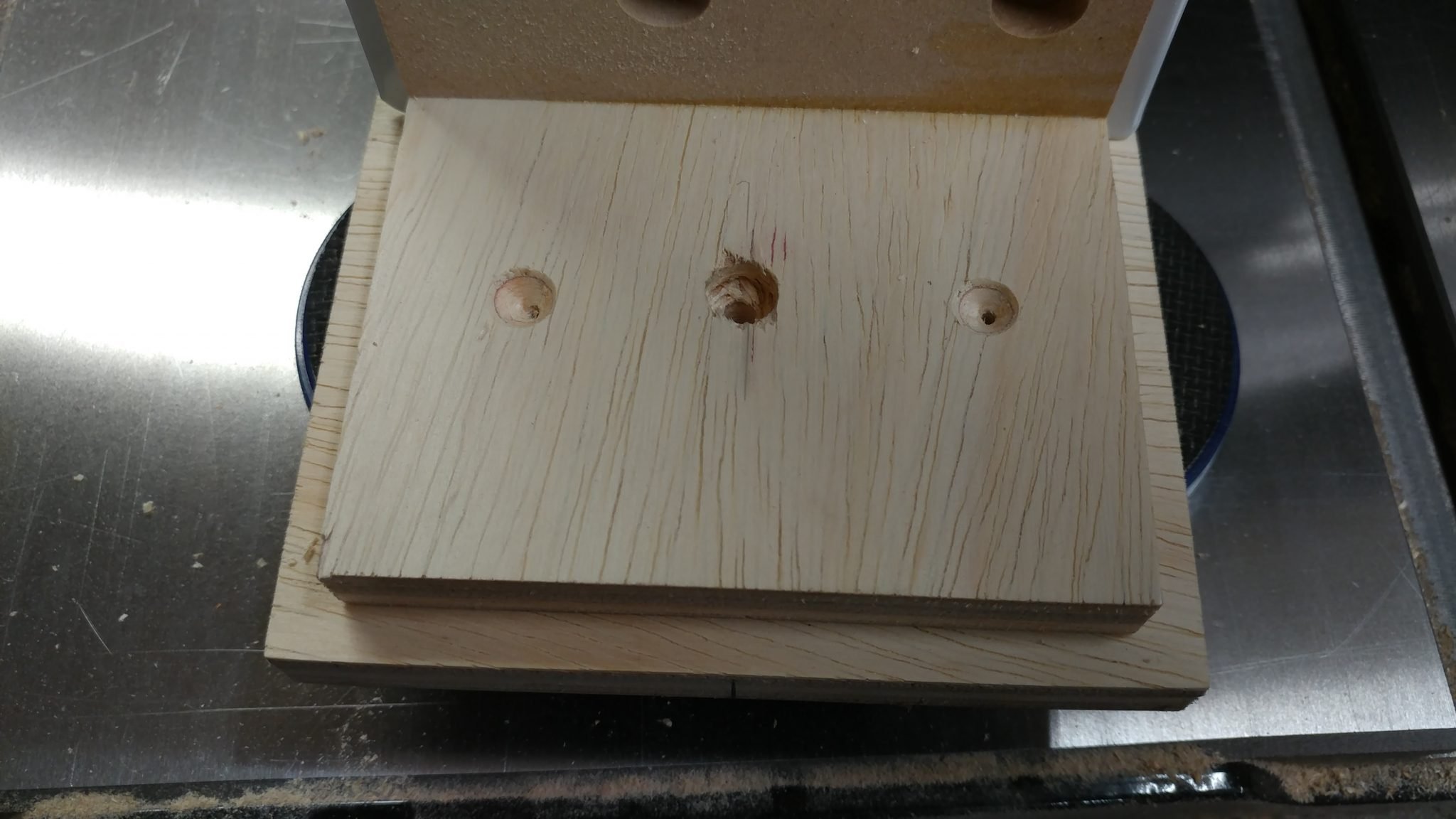
Then I removed the drawer and drilled and countersunk some holes for drywall screws. I also drilled a hole for the knob hardware. The screw wasn’t quite long enough to go through both pieces of plywood so I had to drill a recessed area for the head of the screw.
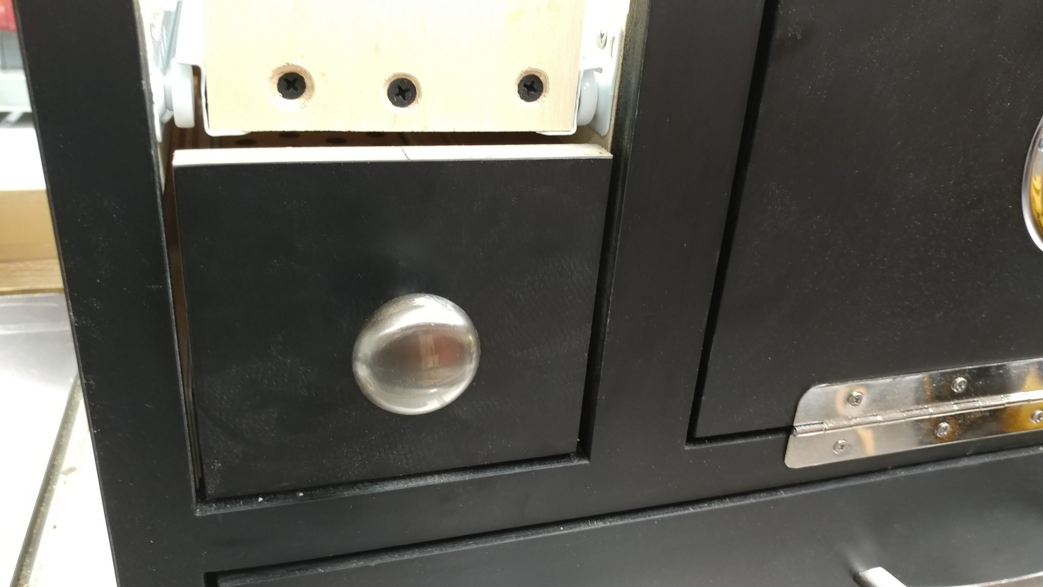
Then I attached the knob.
After that, I repeated the process for the upper drawer then I painted their edges like I did for the other drawers.
Installing the electrical
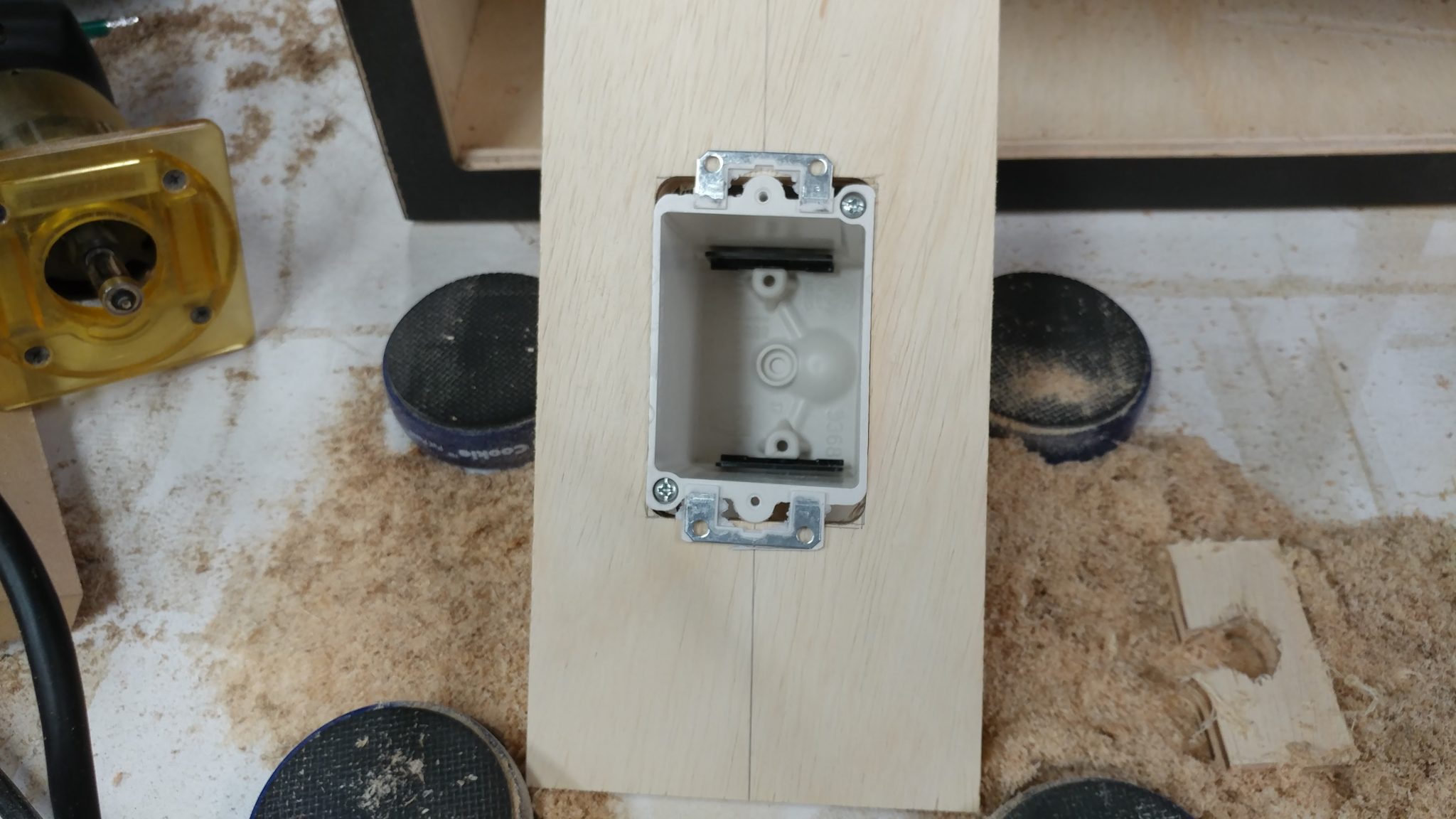
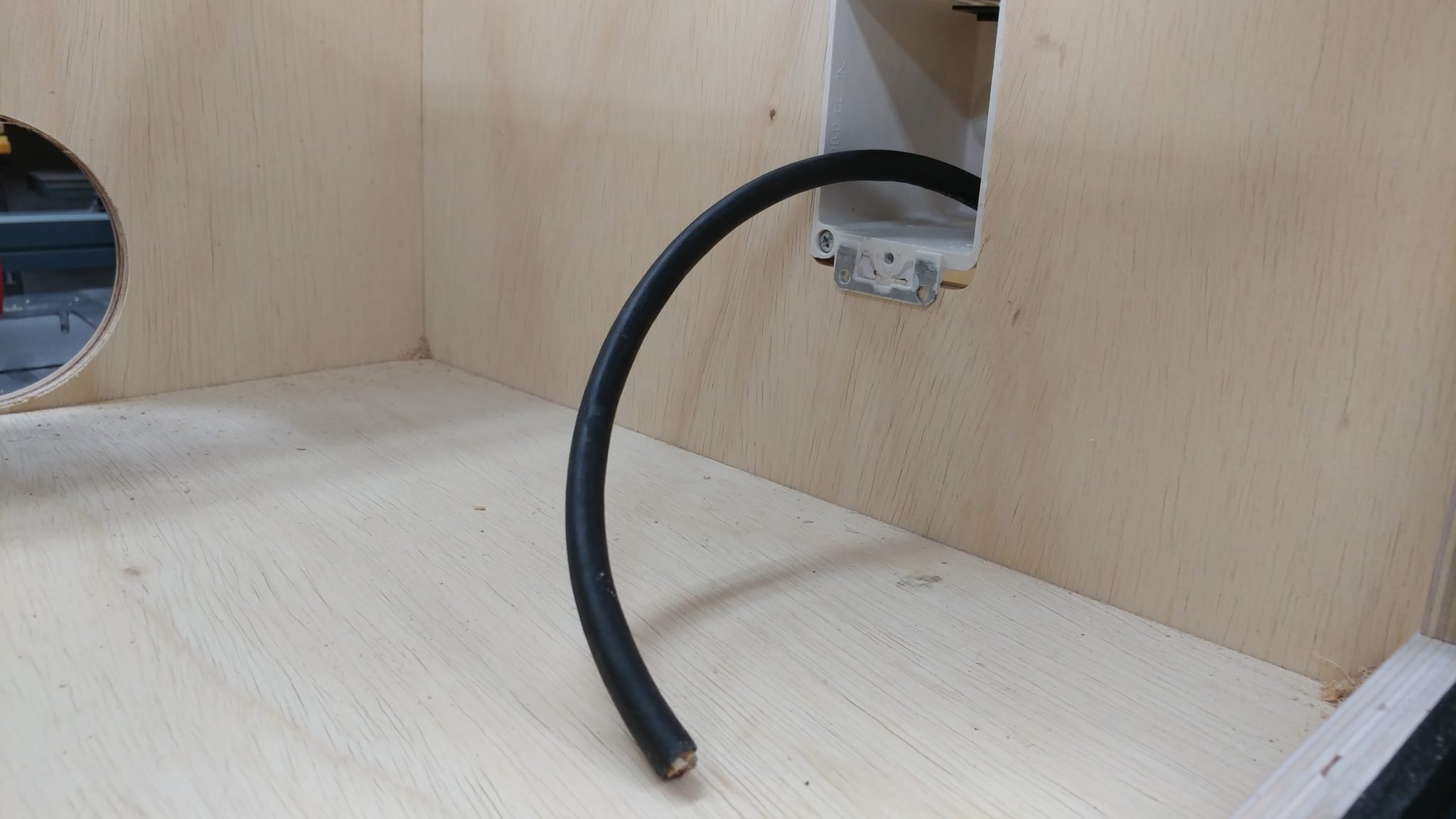
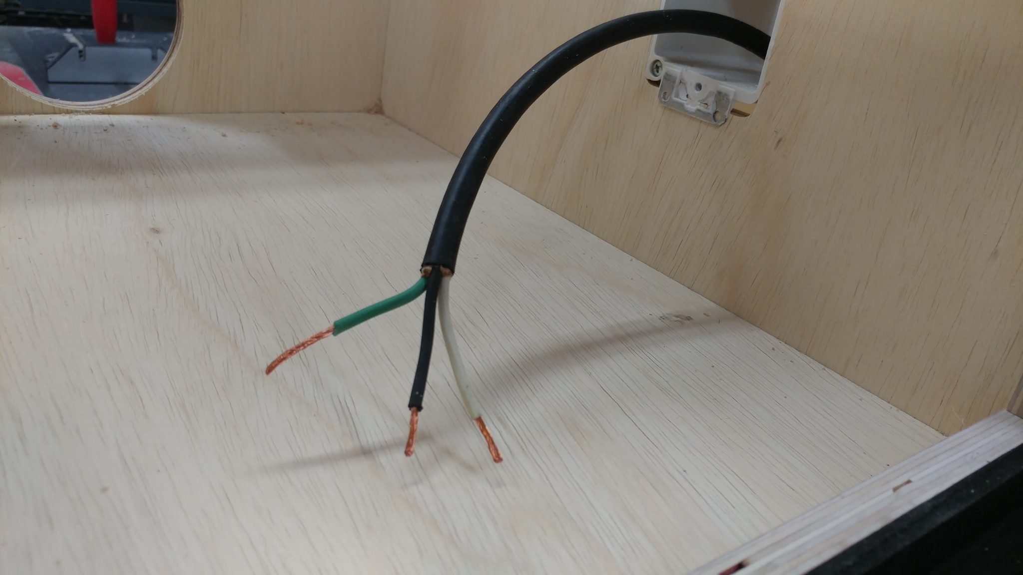
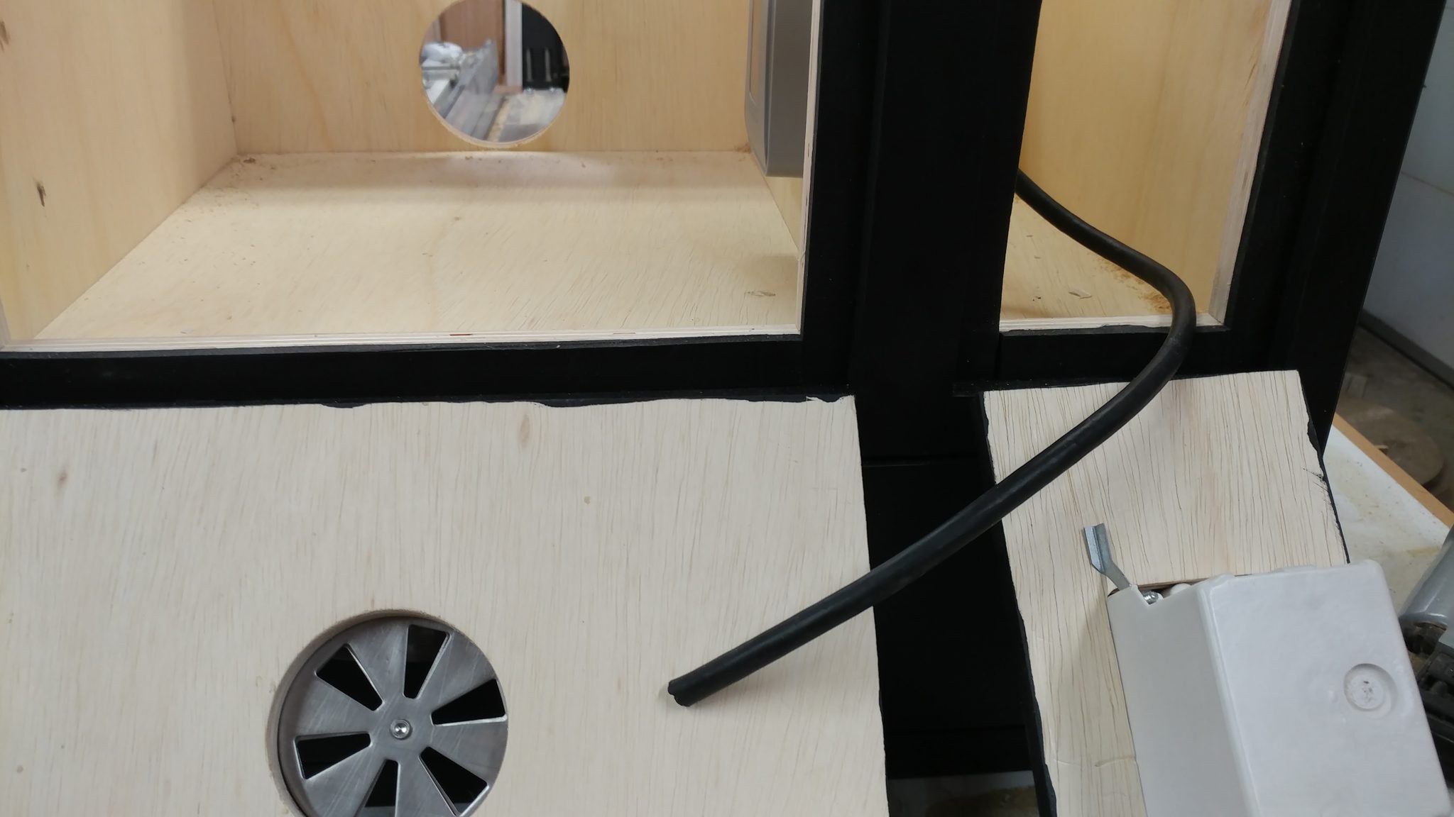
To hook everything up, I’m going to need two lengths of 3-conductor S.O. cord, which can be purchased at nearly any home improvement store. I bought a 10′ length and inserted one end through the electrical door and routed it through the electrical box on the inside of the main cabinet.
3-conductor S.O. cord has just that…3 conductors. In this case, it’s a hot, a neutral, and a ground. This is a standard setup for 110 VAC systems. I start by stripping the wire to exposed the stranded wires, which I then twist so they are easier to work with.
I hook up these wires to the outlet just like you would when installing any standard electrical outlet. Black to the gold terminal, white to the silver, and the green to the ground terminal.
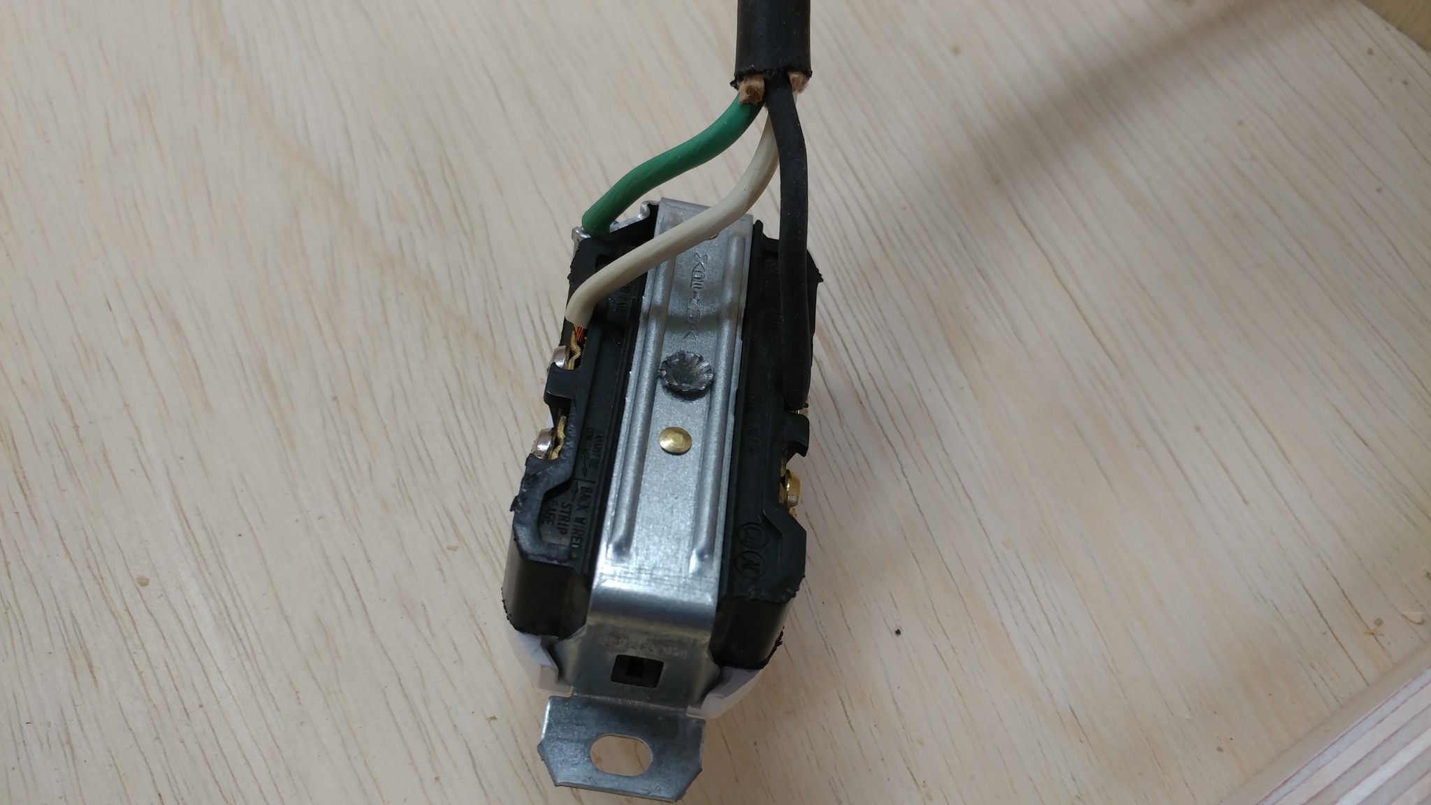
I then fed the wire back into the electrical box so the outlet would sit flush. I’m not securing it at this time.
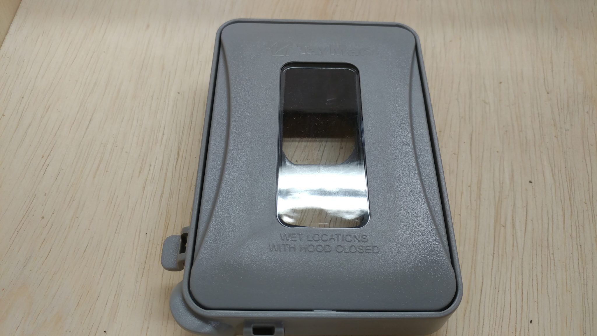
I got an outlet cover to help keep the sawdust out. It turns out that this was a bad choice as I will explain later.
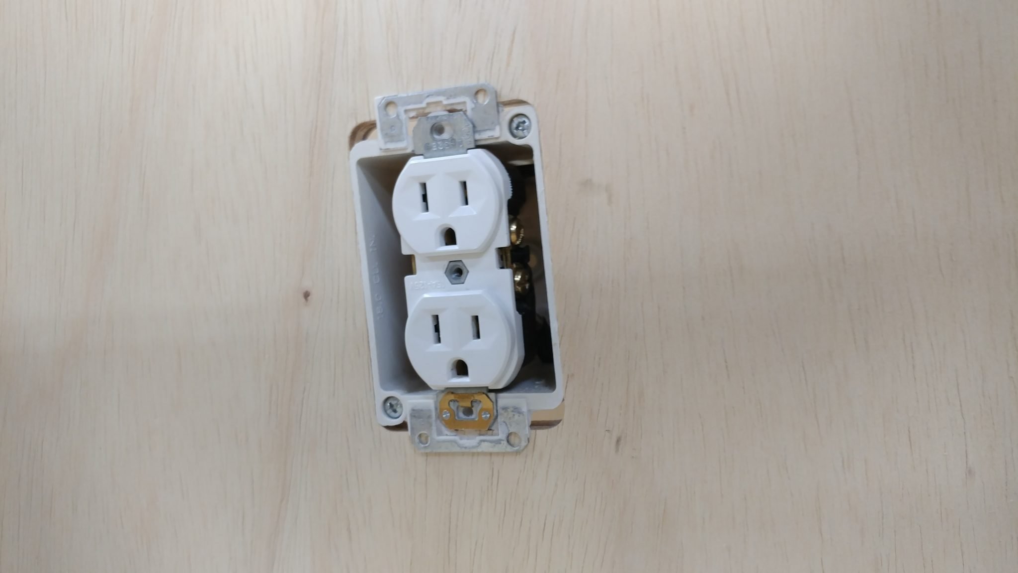
I installed the outlet faceplate which also secures the actual outlet into the electrical box.
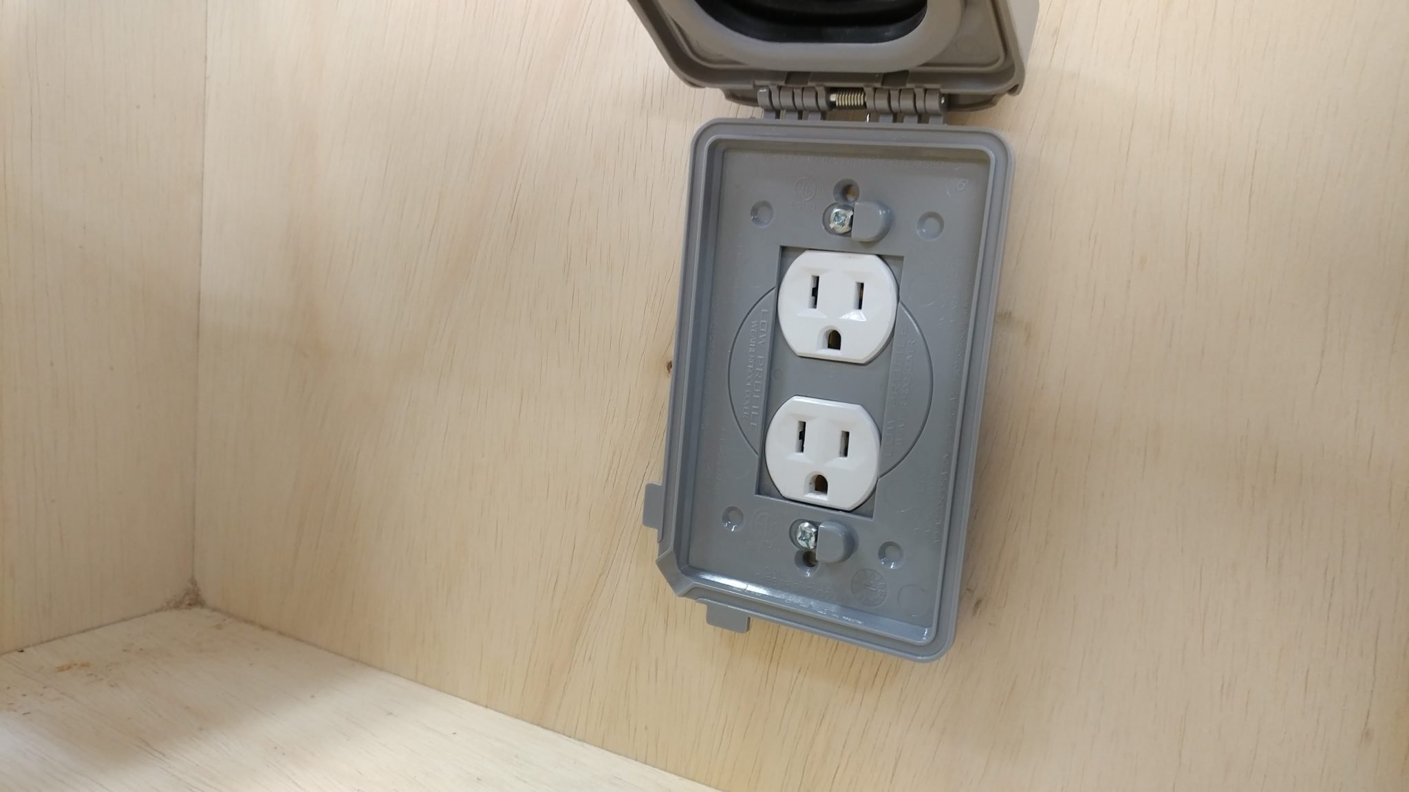
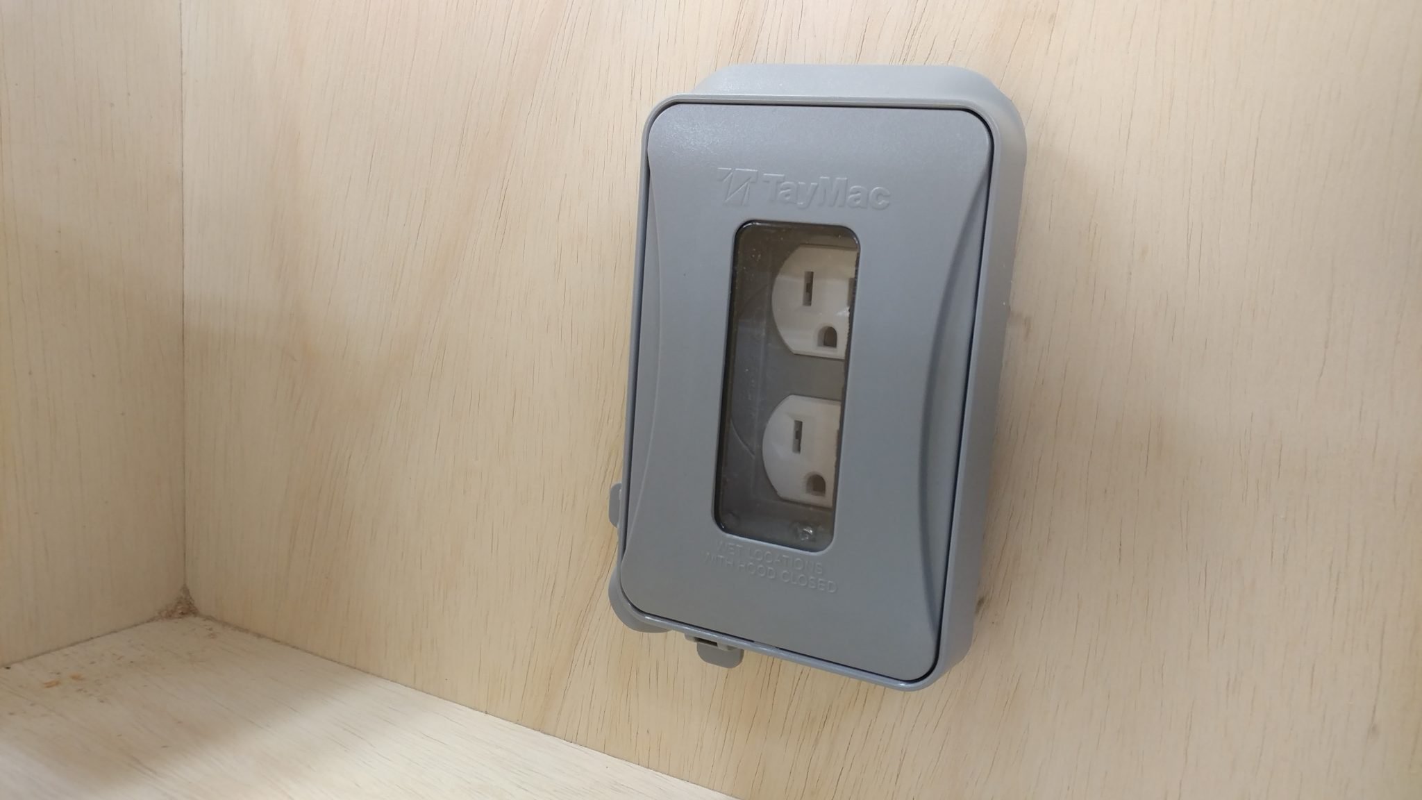
The box then flips down to cover the outlet.
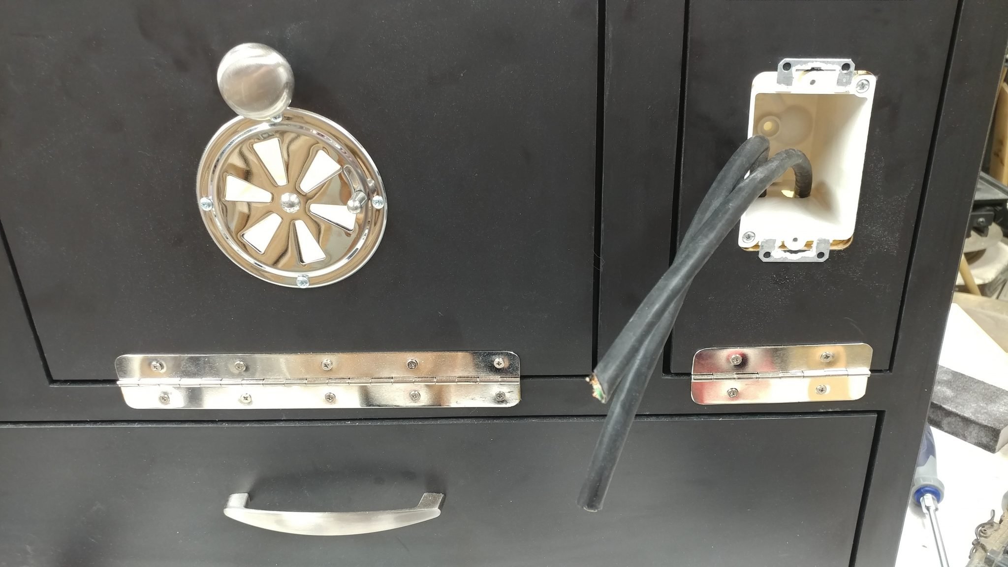
I cut the cord so it would be long enough to reach into the front electrical box with the door open. I’ll come back to this.
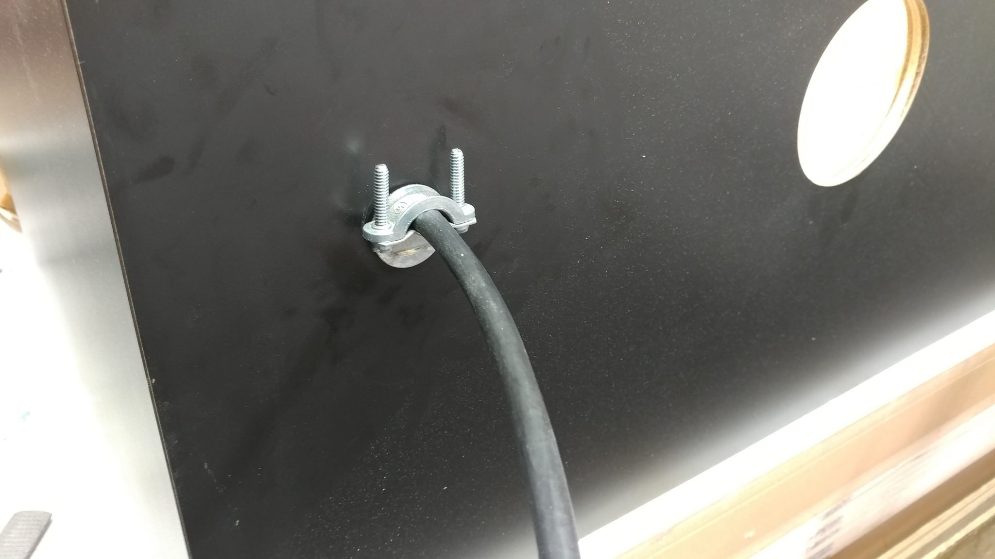
I threaded the strain relief into the smaller hole in the back.
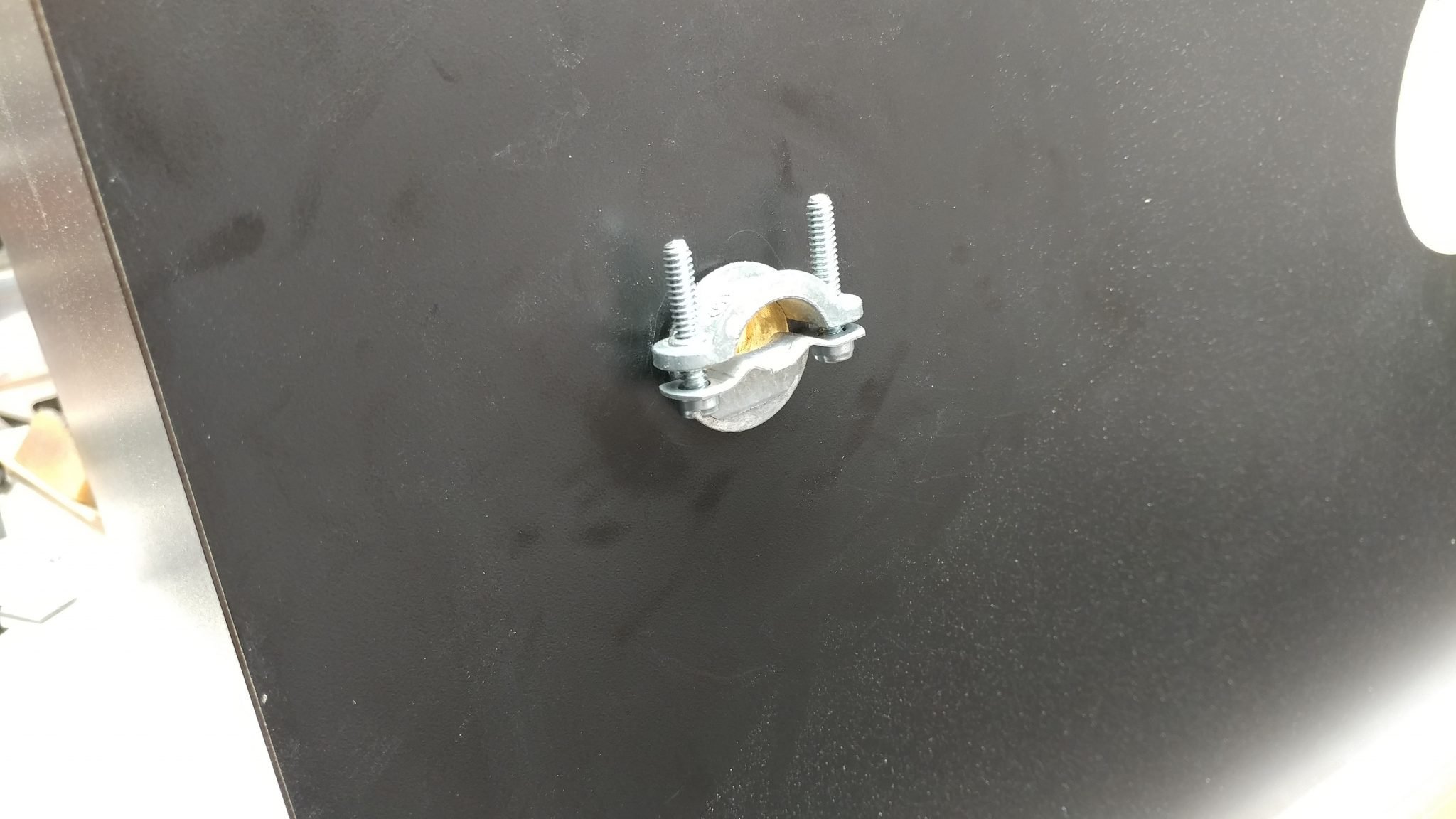
I then fed the rest of the cable into that hole far enough to reach the front electrical box and then tightened the strain relief screws.
Then it was time to feed both cables into the front electrical box.
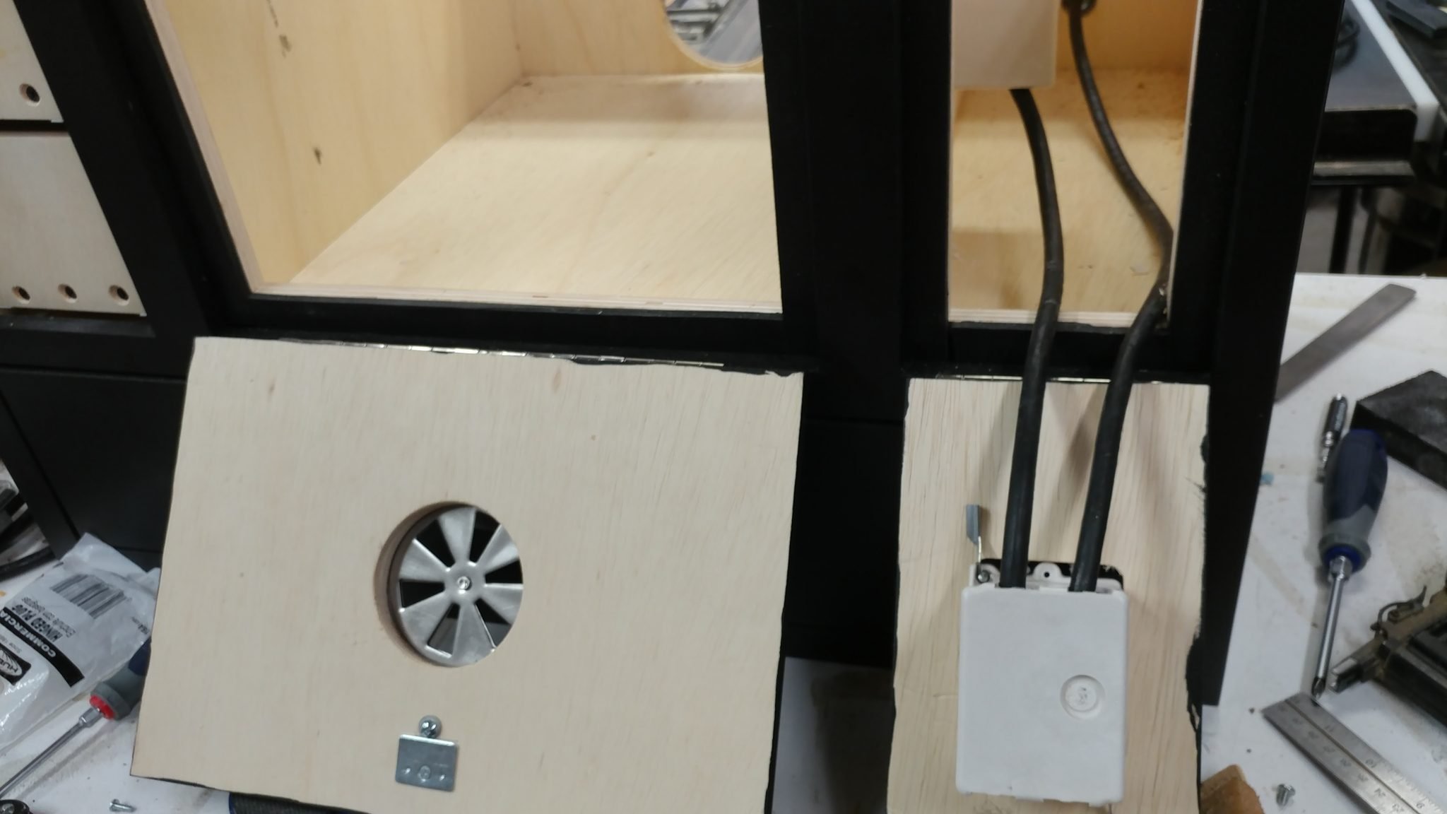
I closed the door so I could finish the wiring.
I stripped the wires and bent the hots and neutrals so they would go around the screw terminals easier. The grounds can stay straight since they will be connected together with a wire nut.
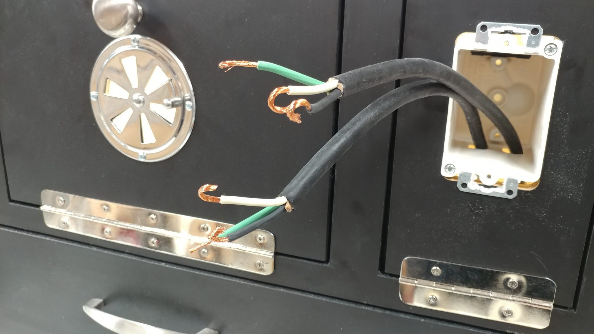
This will vary by switch but I just wired the hots and neutrals according to the directions.
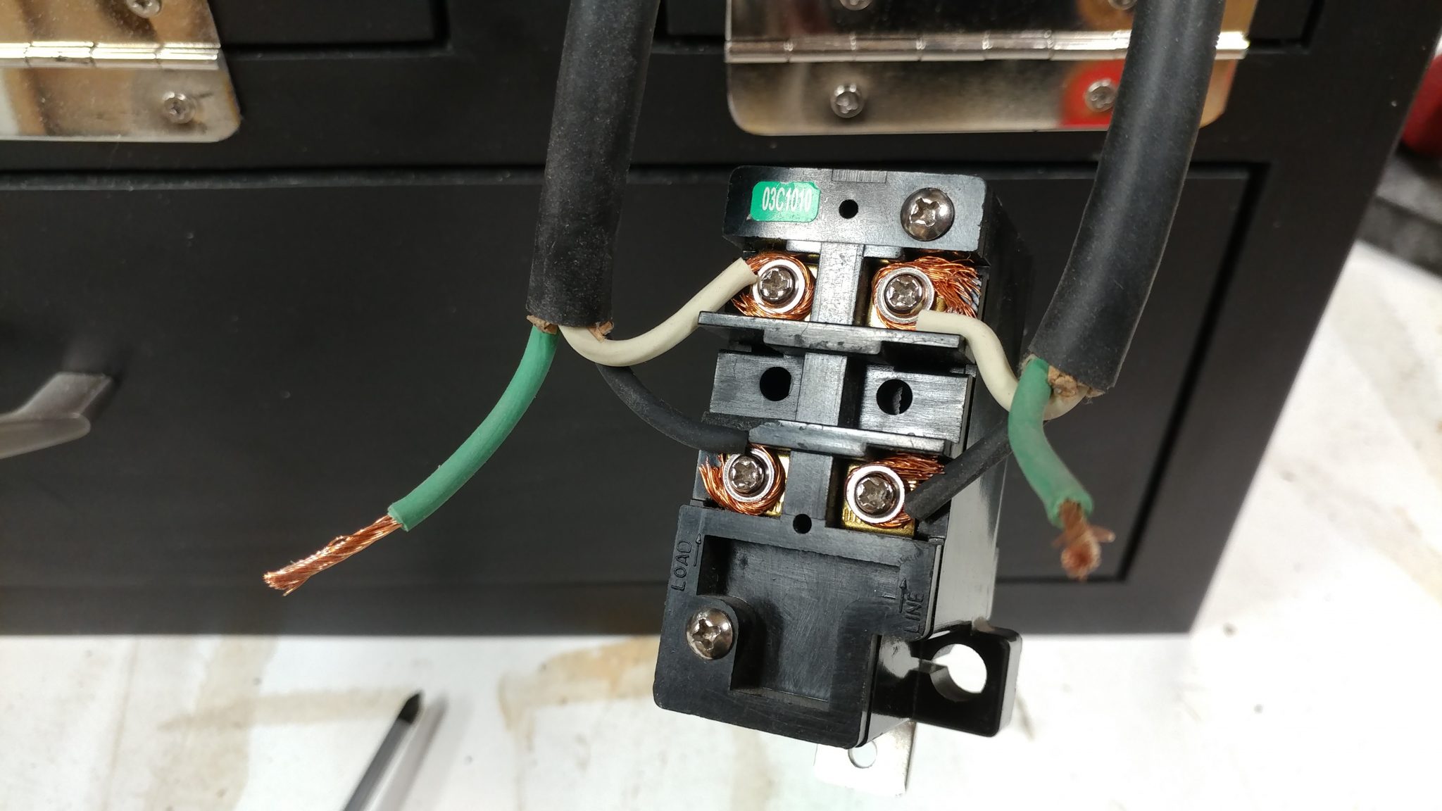
The ground wires are tied together with a wire nut.
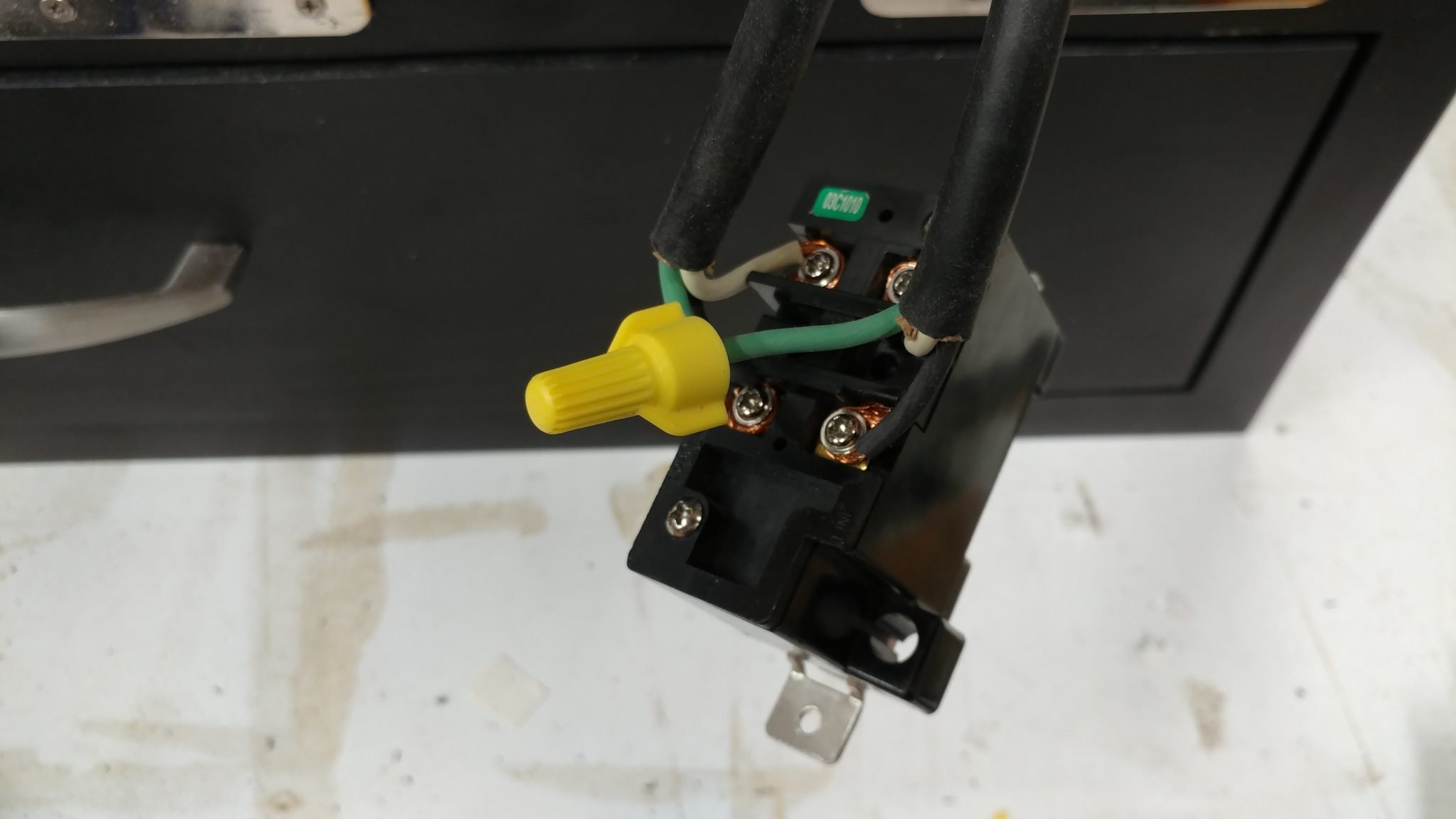
The switch body is then inserted into the electrical box and the extra wire is fed back into the cabinet.
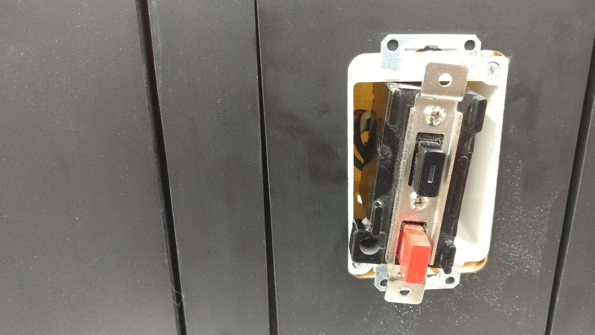
Then I attached the faceplate for the main switch.
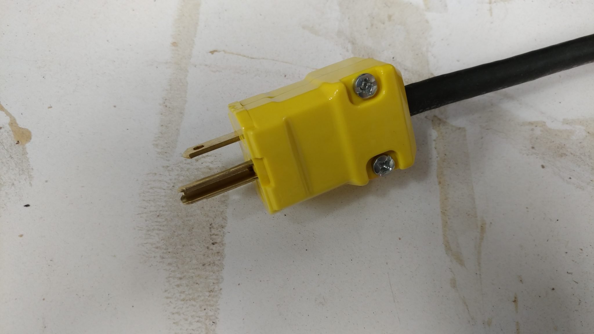
The only thing left on the electrical is to connect a plug to the end of the cable. This is the type of plug that I decided to use.
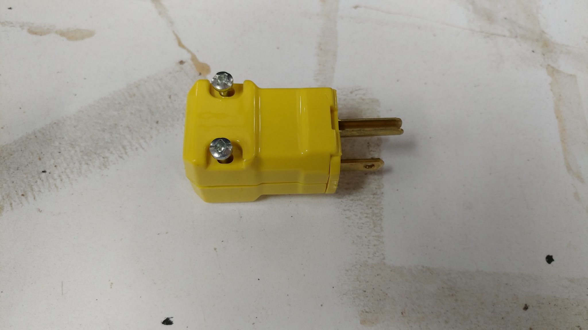
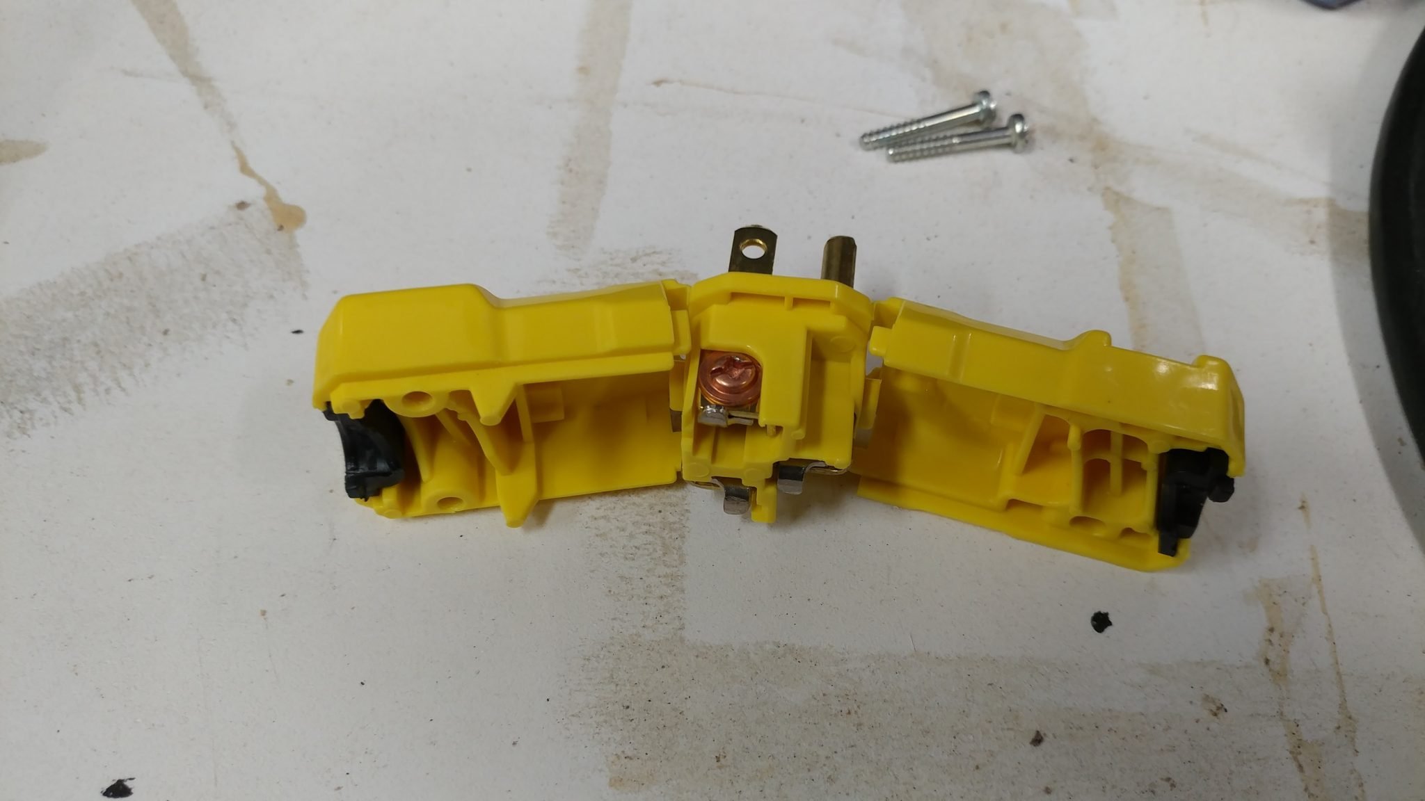
It uses two screws to hold it together. When these screws are removed, the plug hinges open.
Once again I strip the wires and twist them.
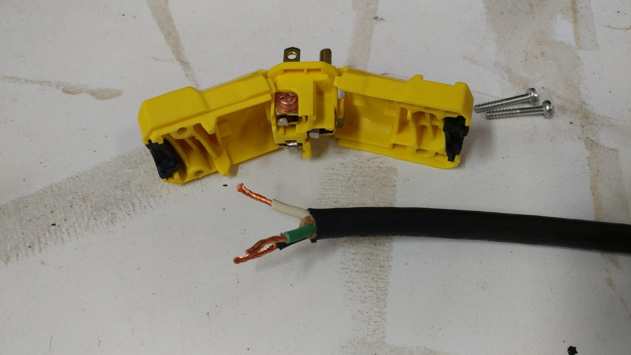
Follow the directions for whatever plug you choose but this one was easy. You just insert them and tighten some screws.
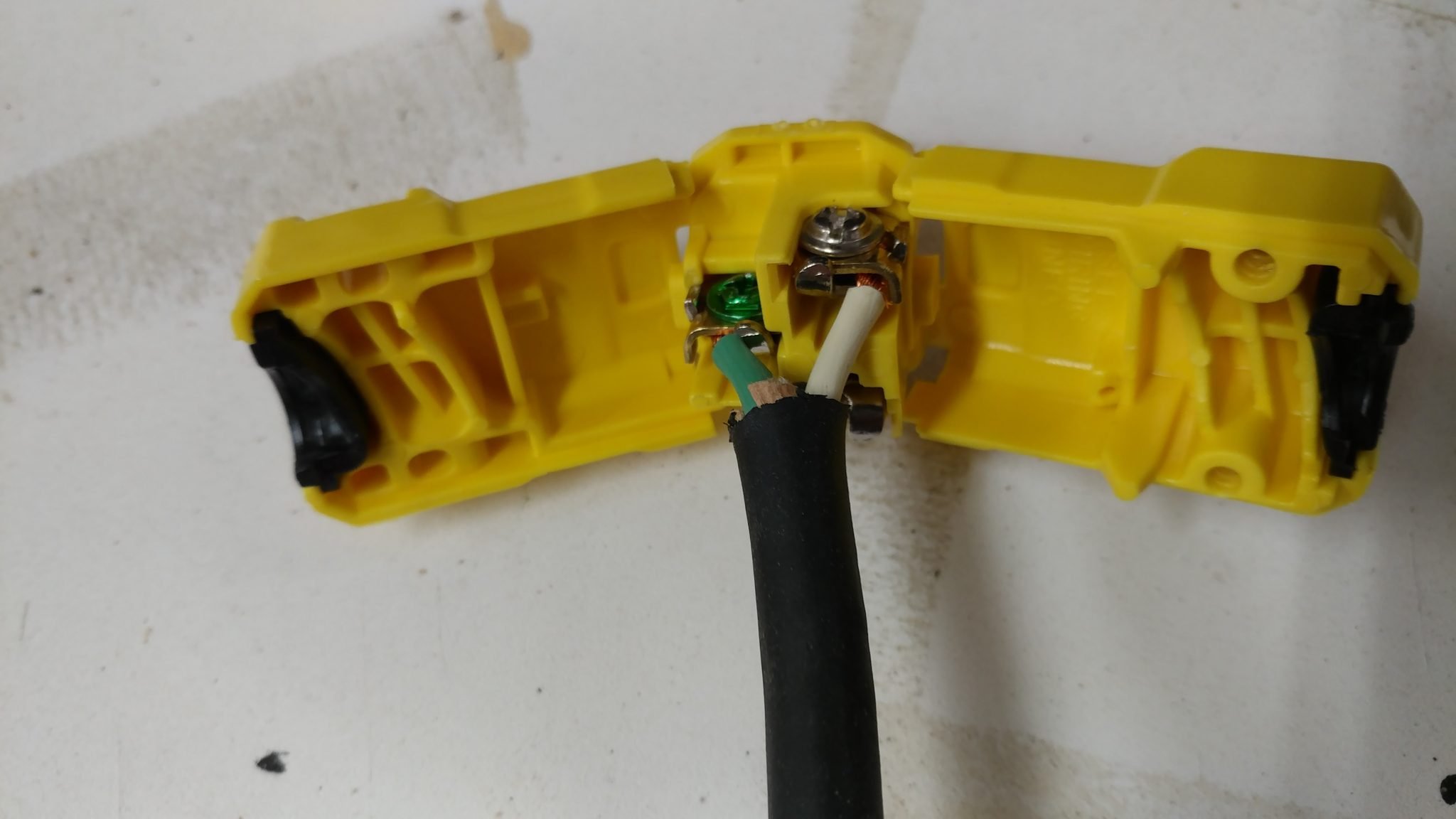
Then I closed up the plug with the two screws I removed earlier.
Electrical is all done.
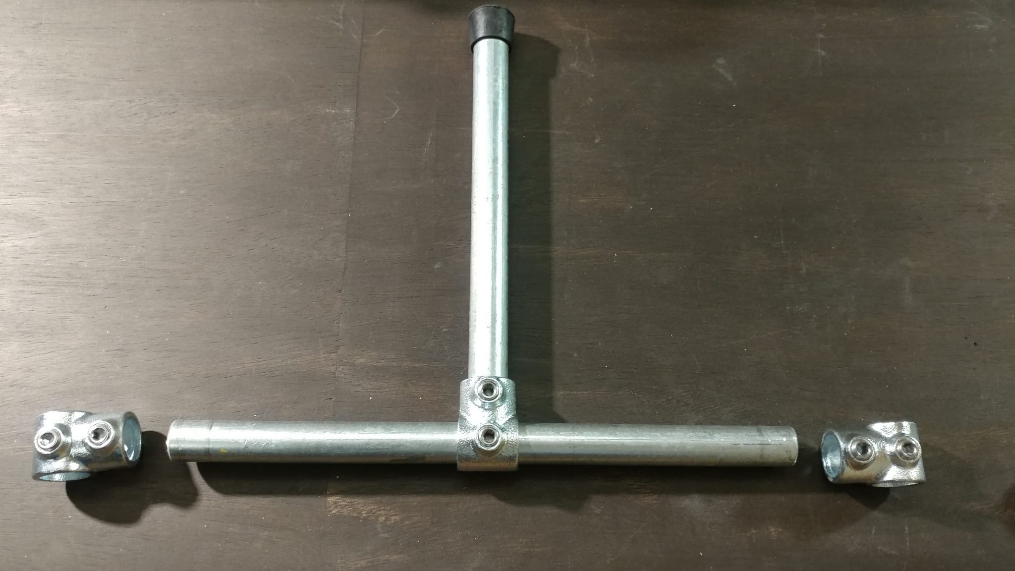
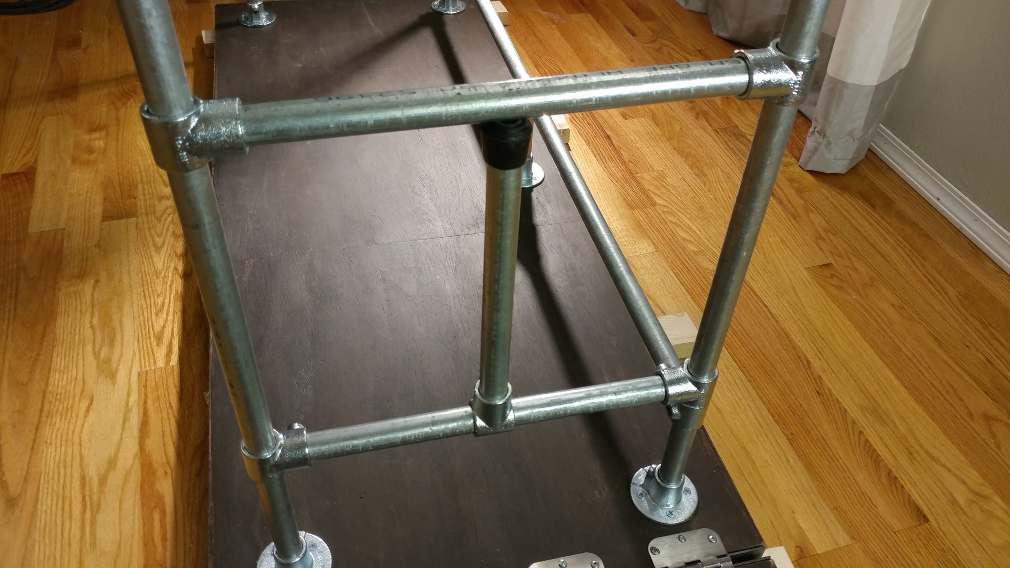
Making the legs
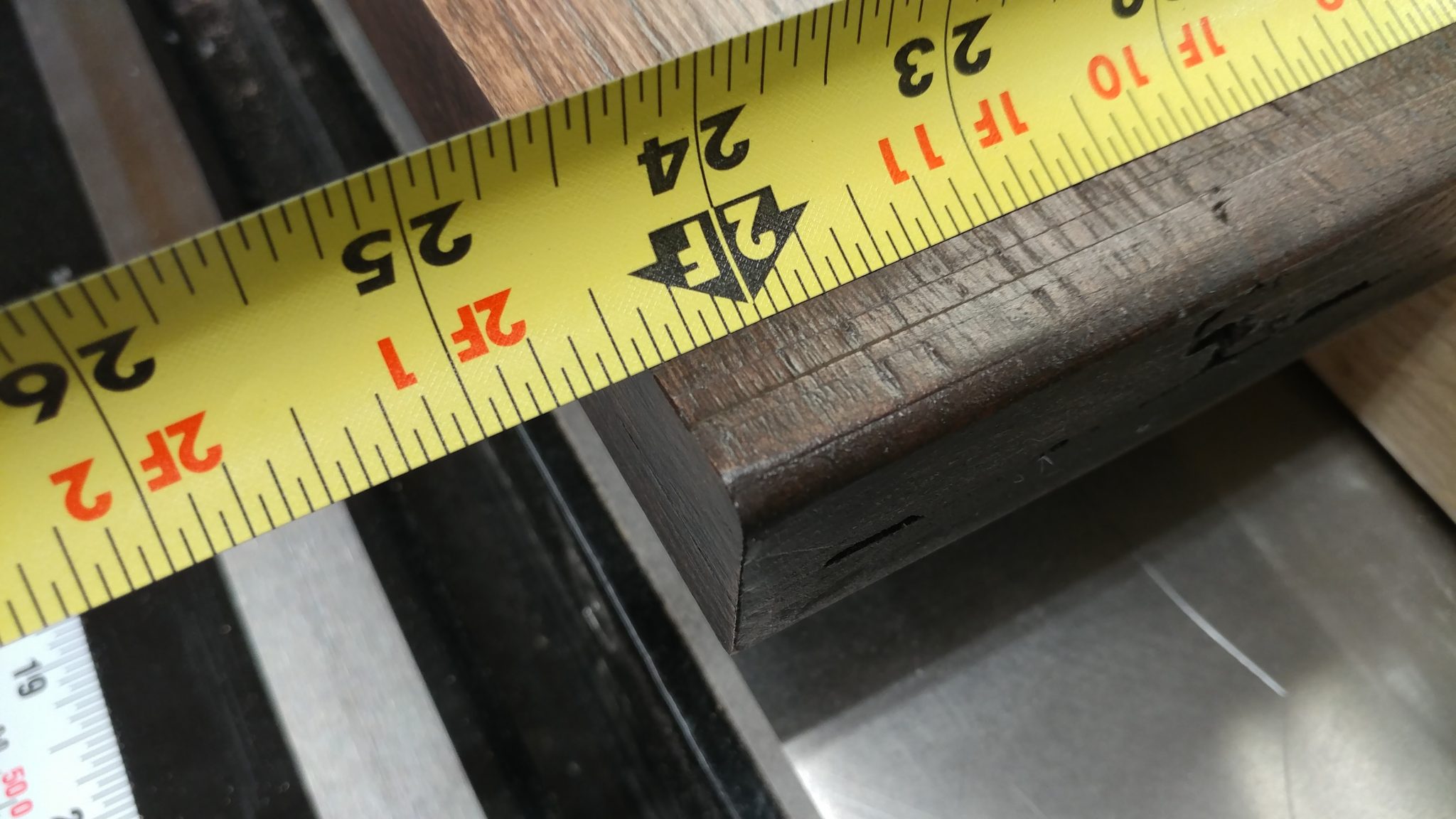
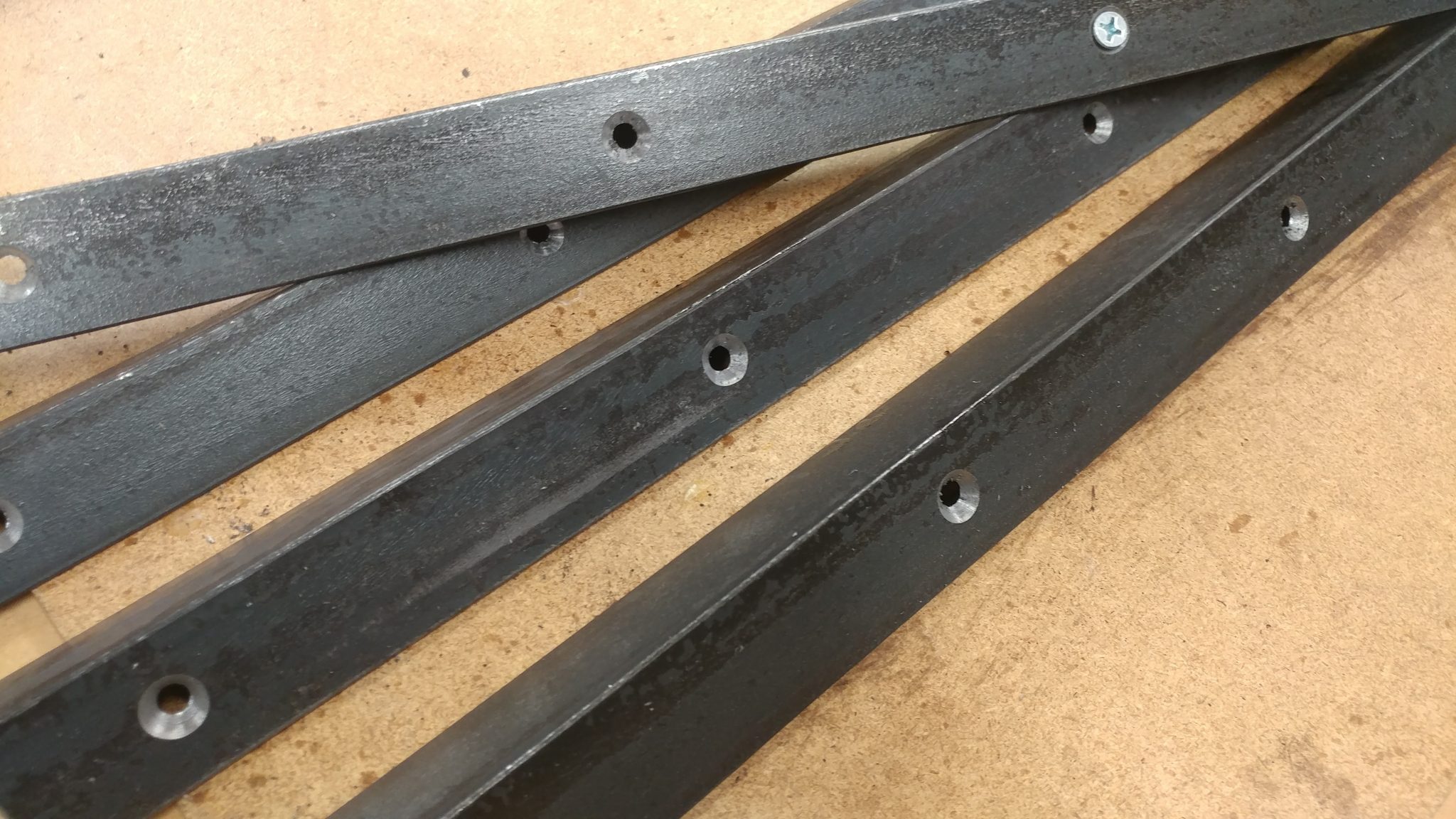
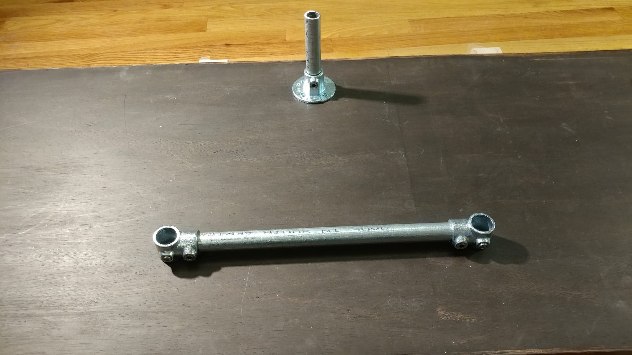
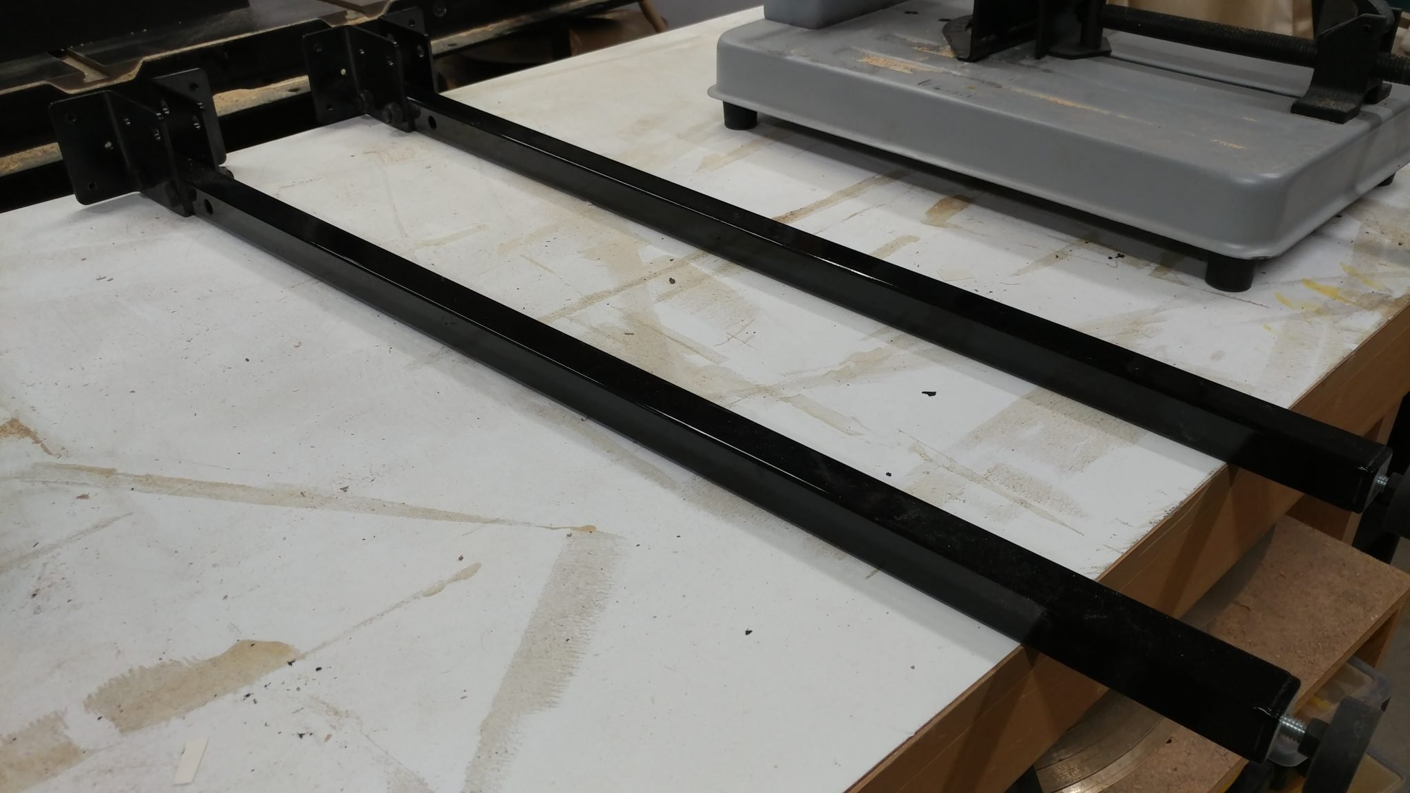
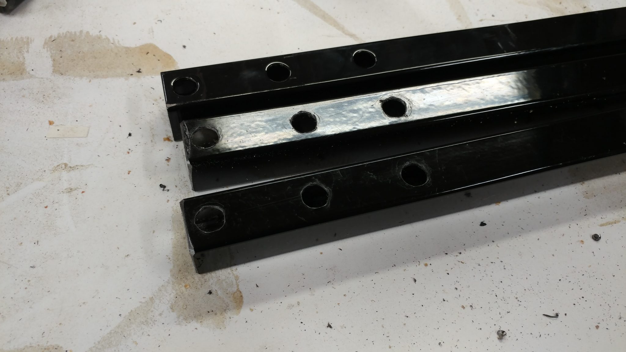
I need to shorten the legs that support the side extension table. One end has holes drilled for the hardware that attaches it to the underside of the actual table. The other has the threaded hole for the feet. I decided to keep the end where the feet screw in since that would be more difficult to recreate than the other end which is just holes.
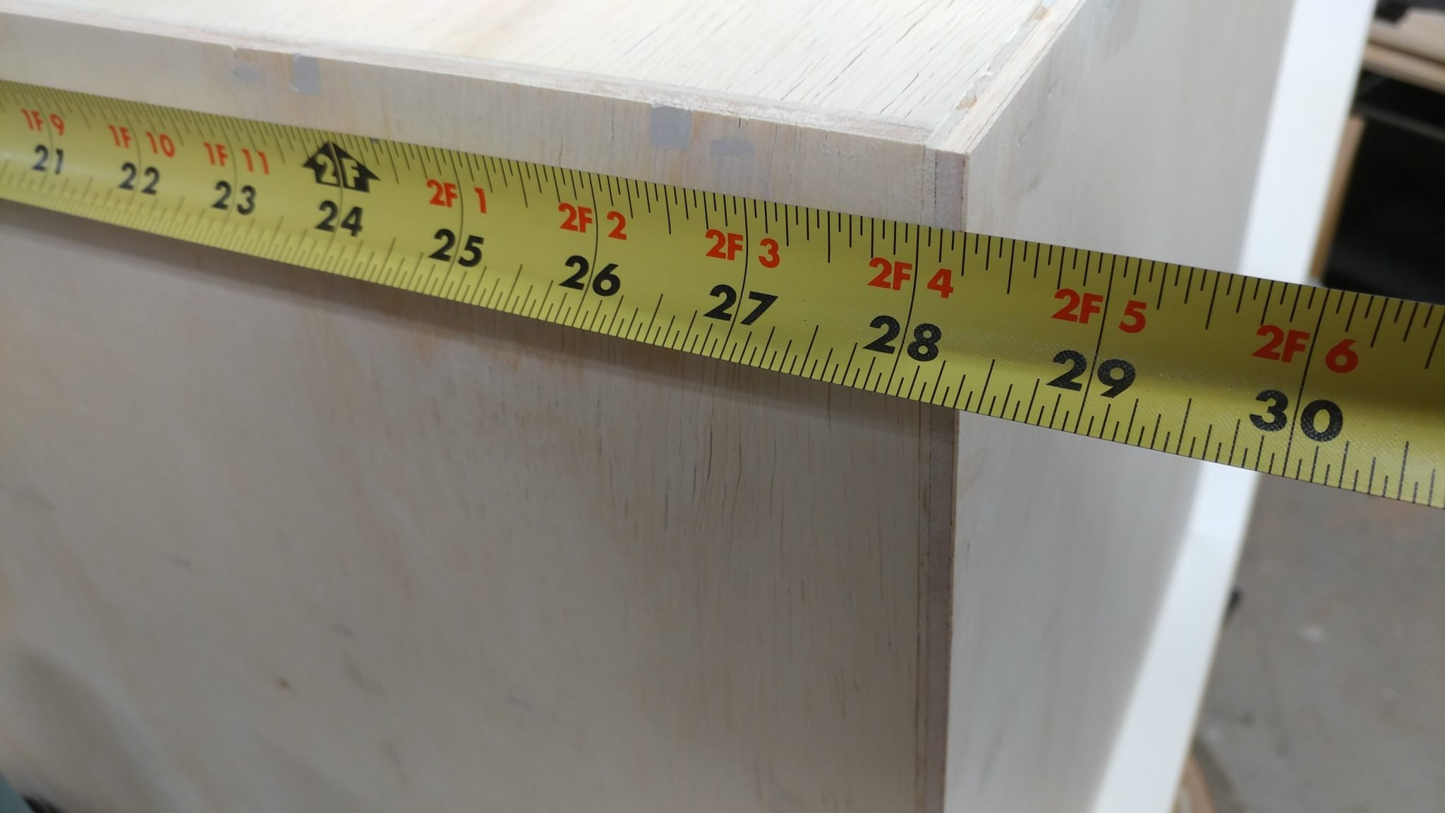
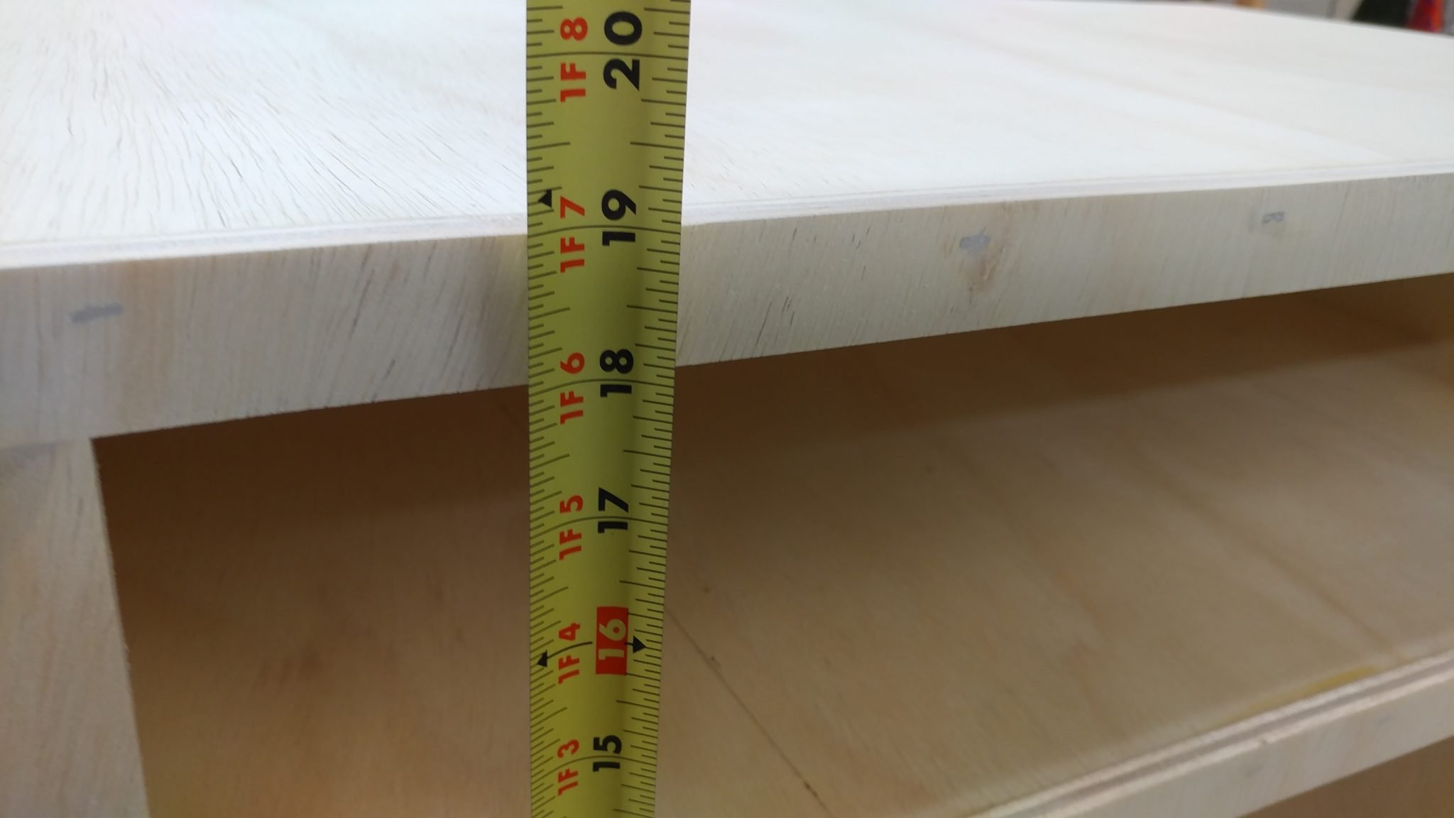
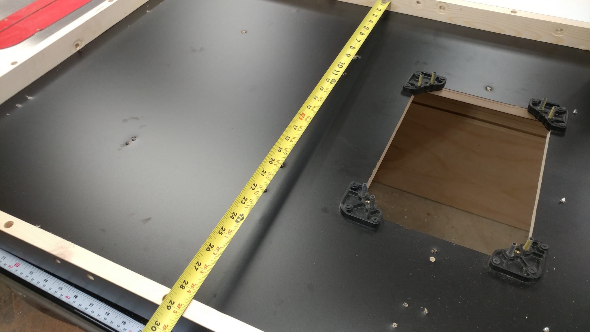
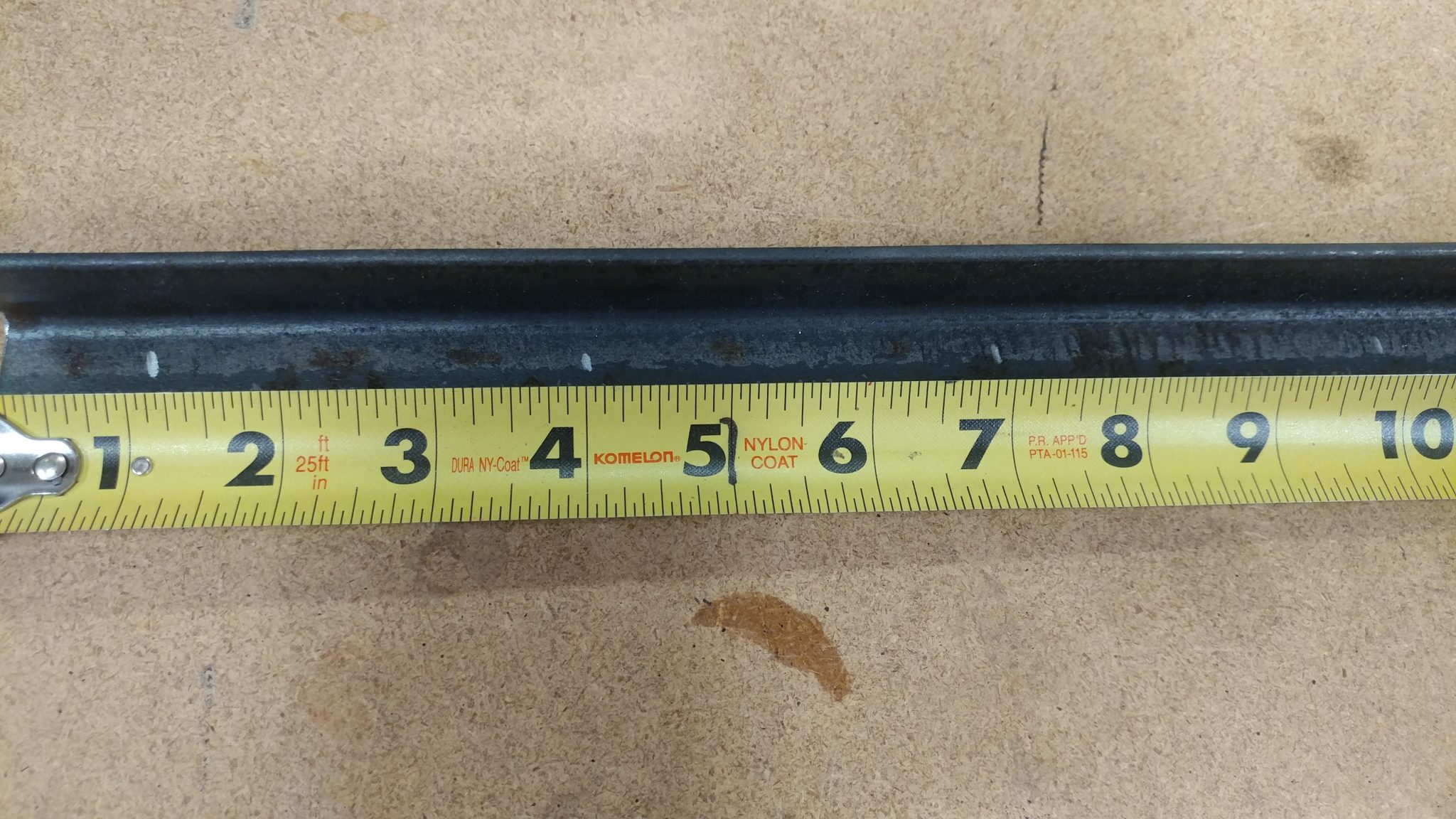
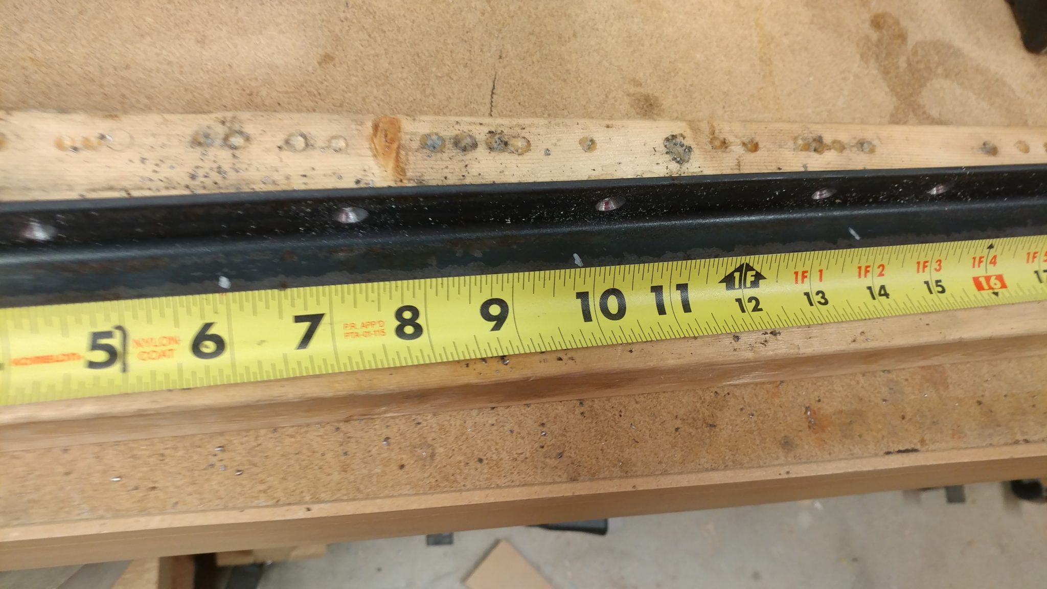
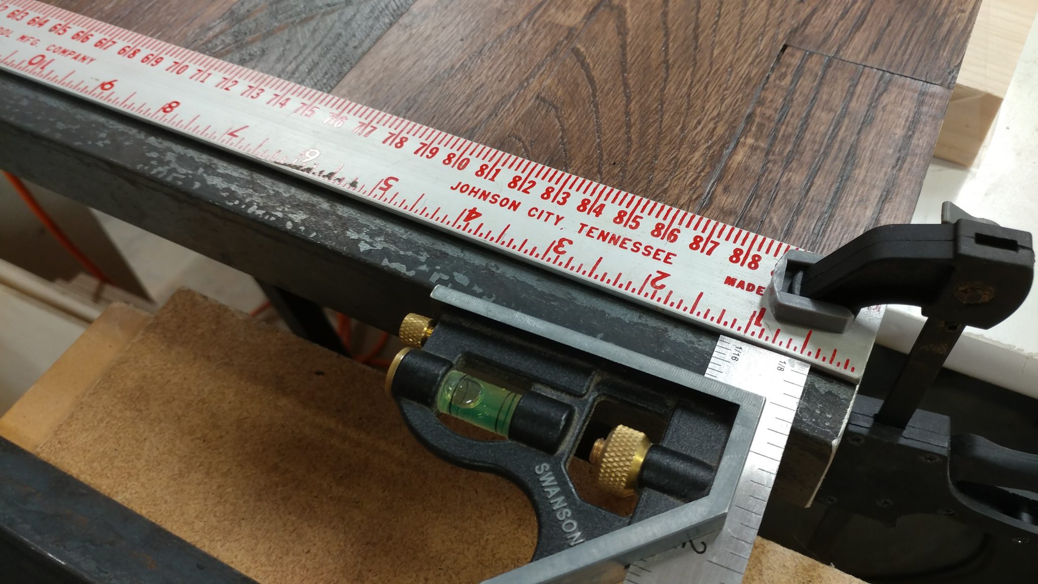
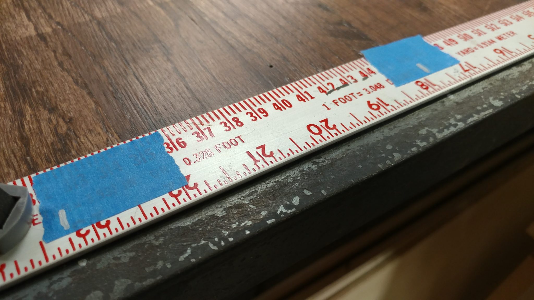
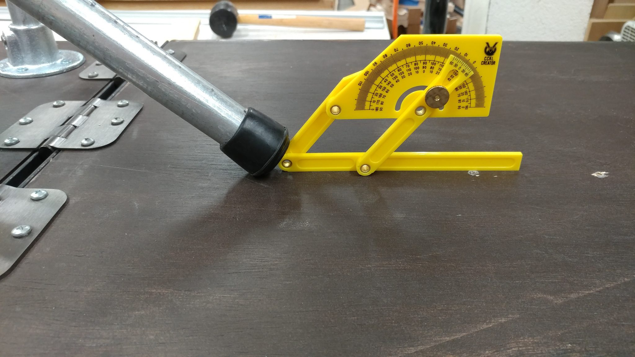
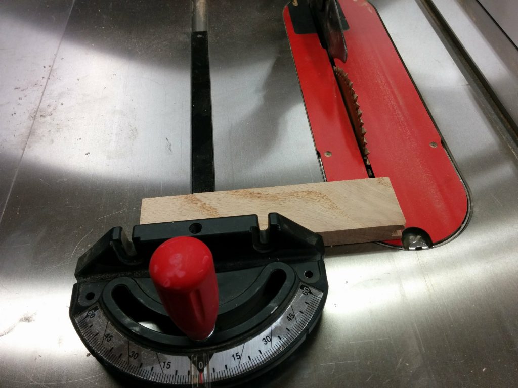
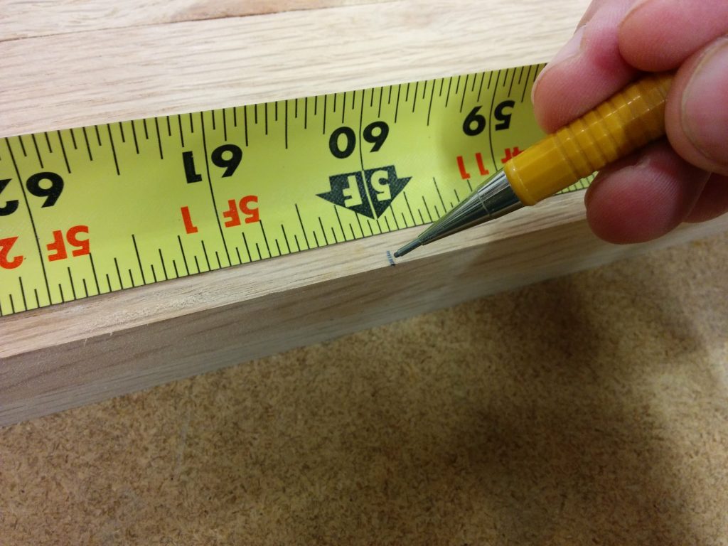
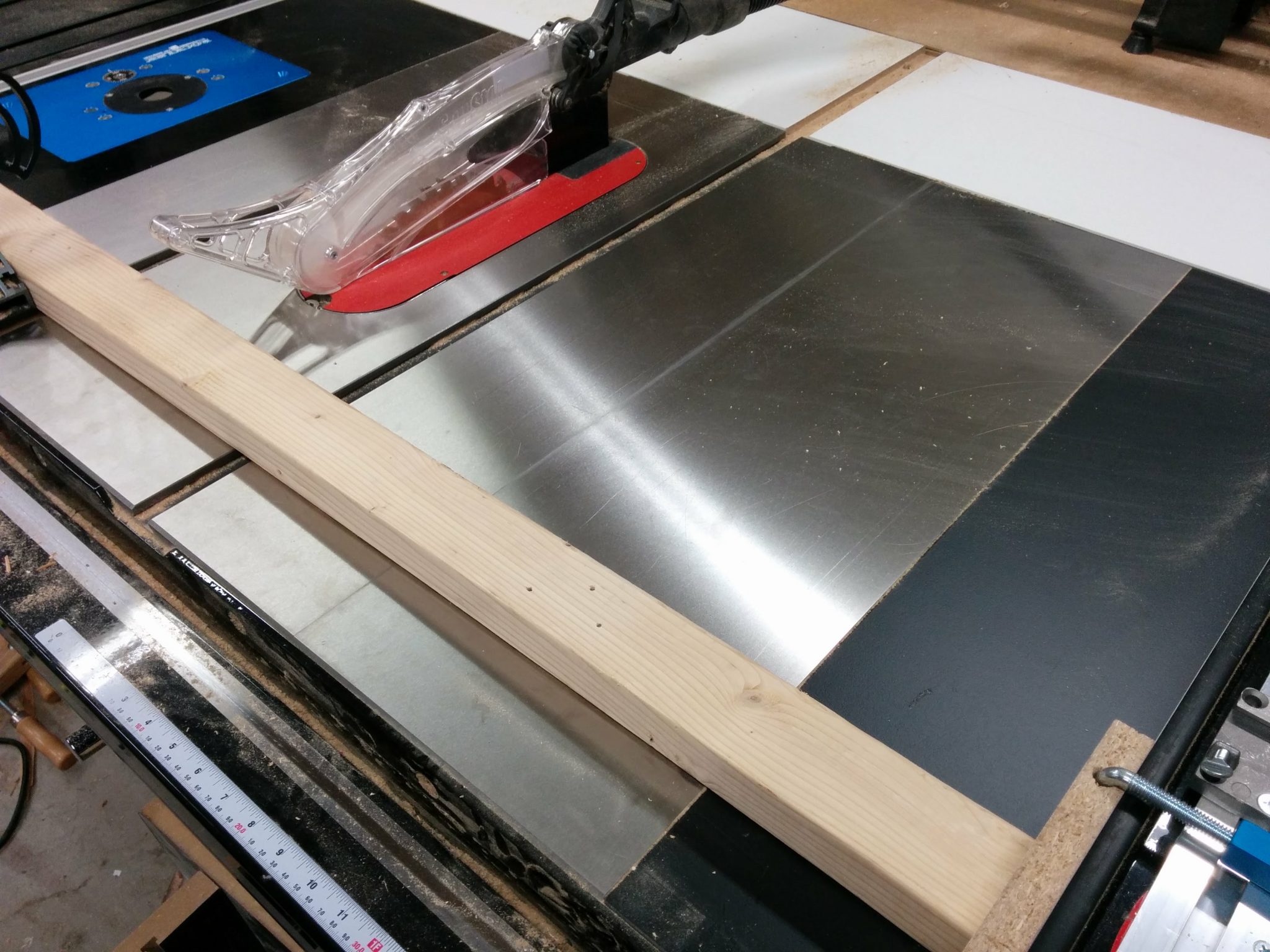
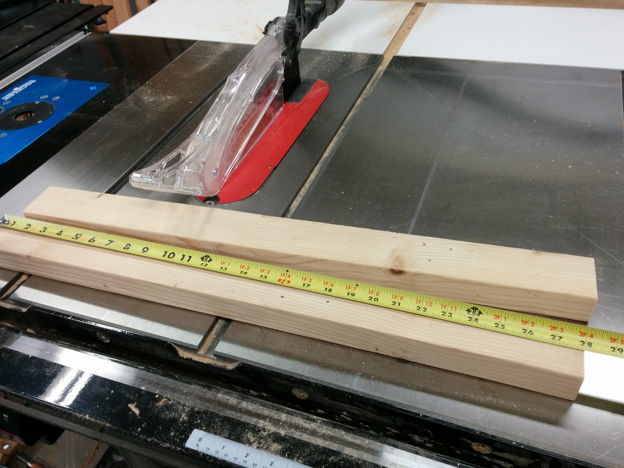
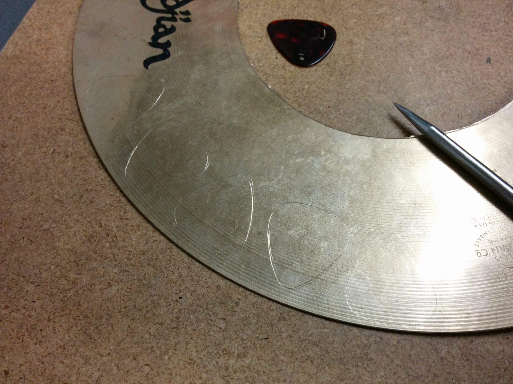
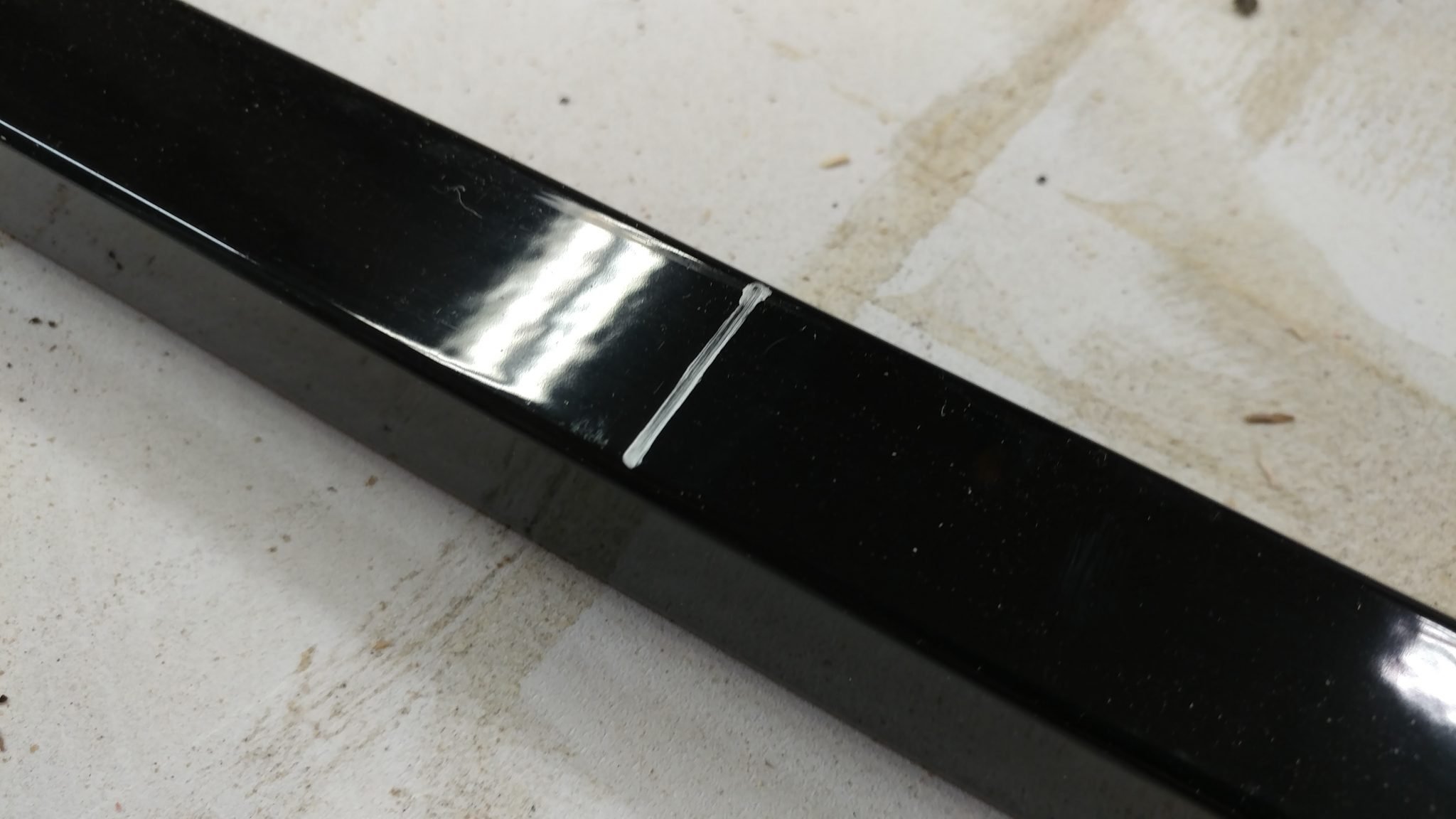
To determine the length of the legs, I simply measured the height of the cabinet. This provided me with the amount that I needed to remove. I then measured down from the top of the legs and marked it with a silver Sharpie. This is where I will cut.
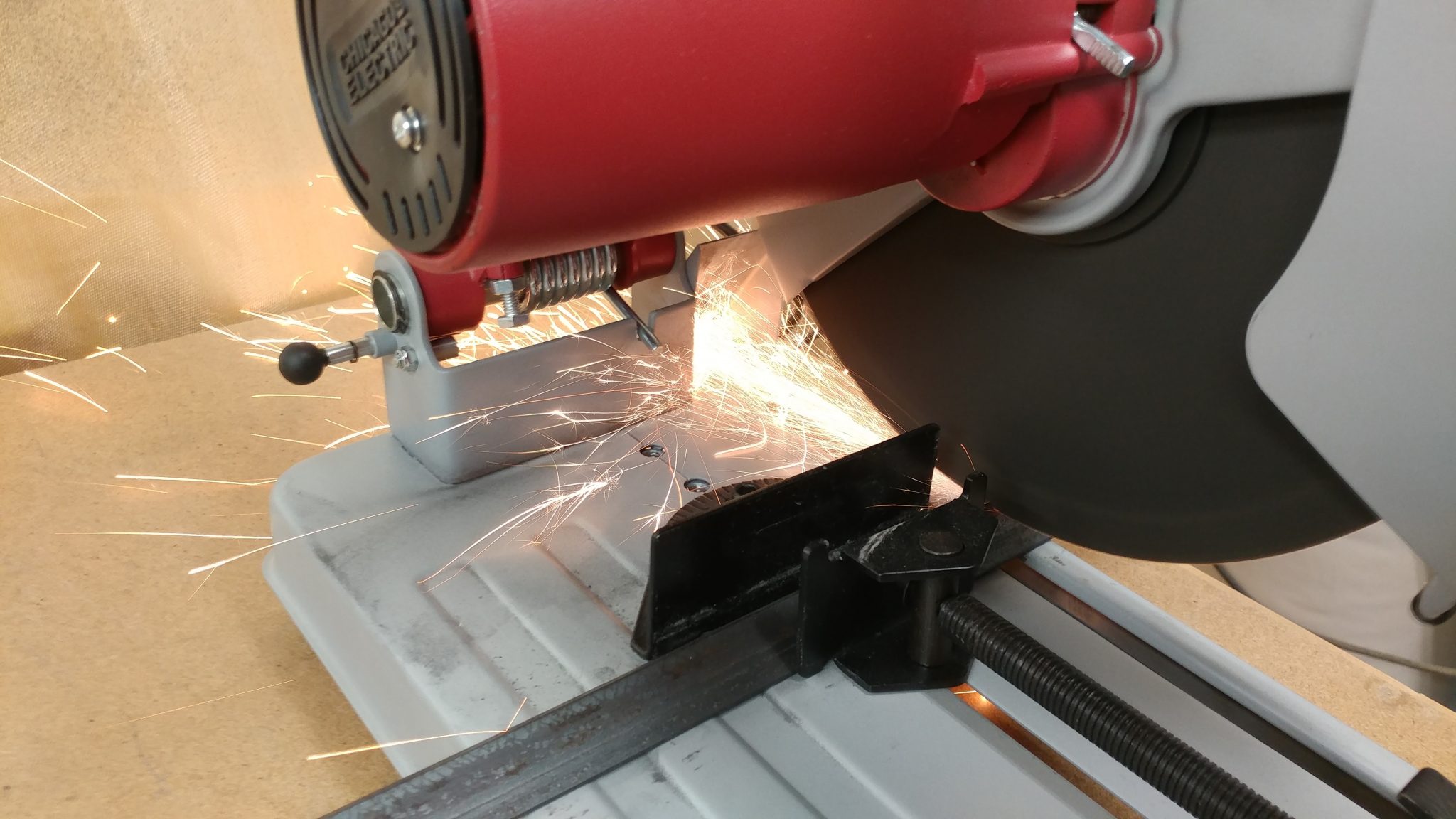
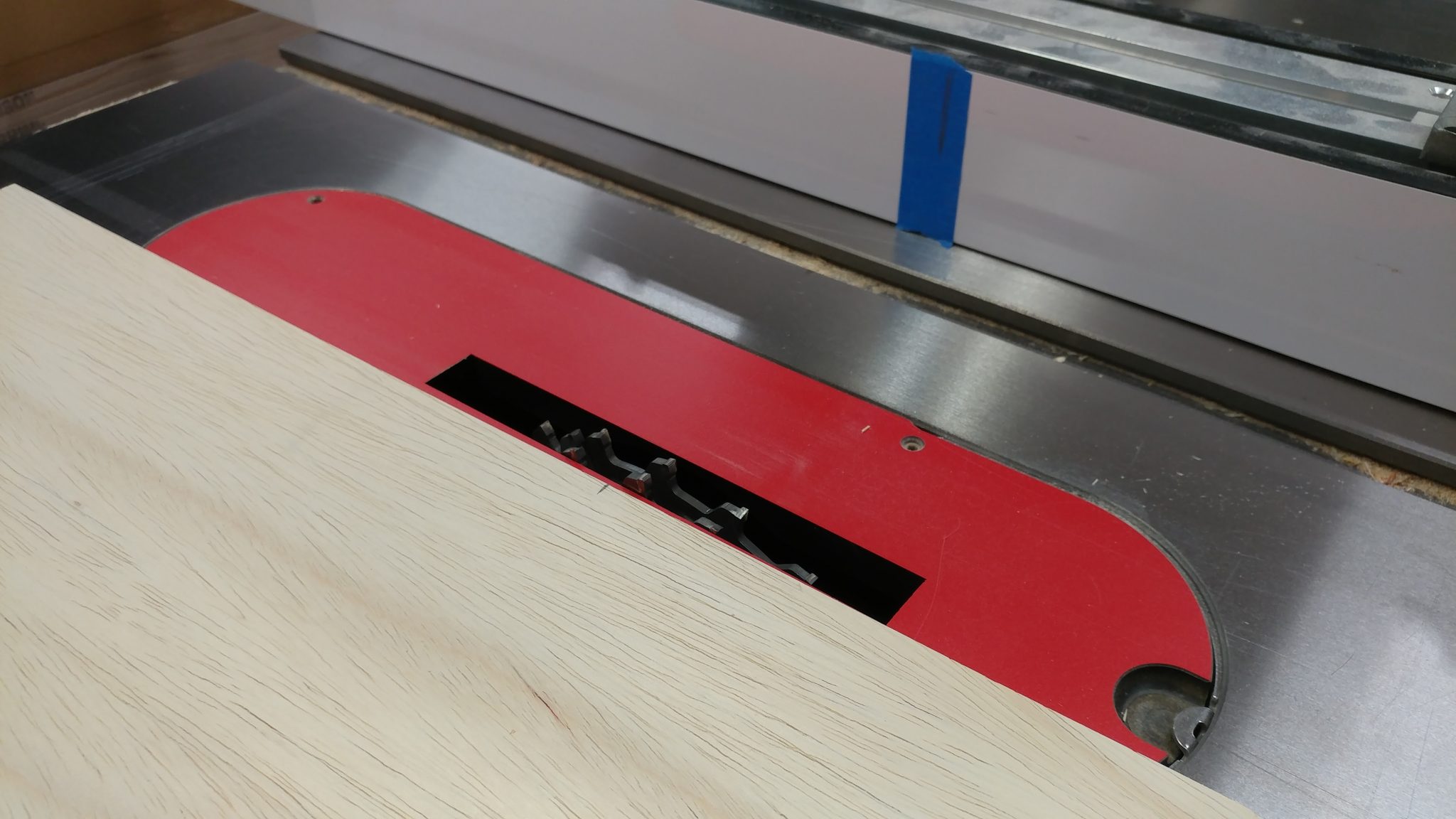
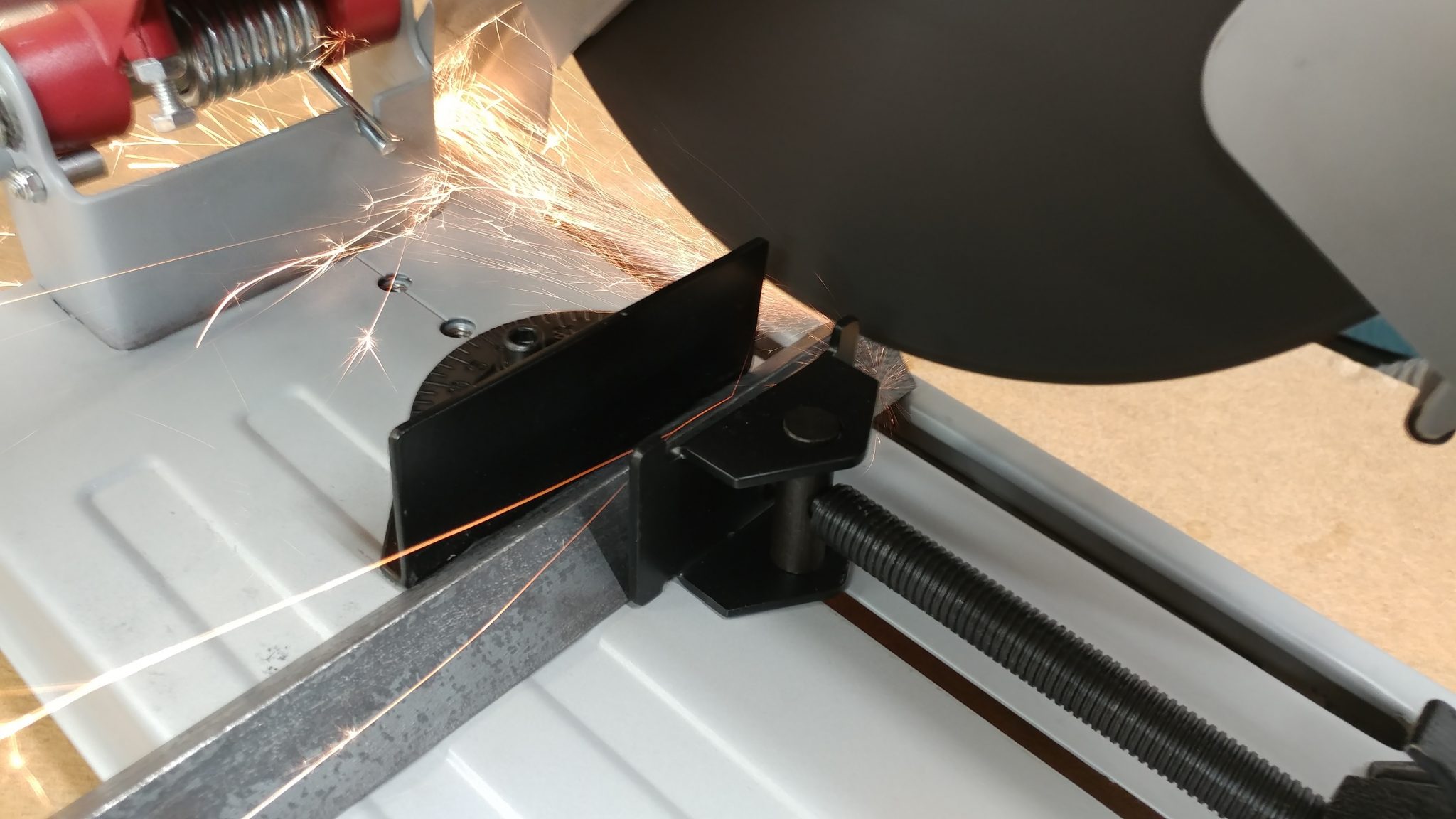
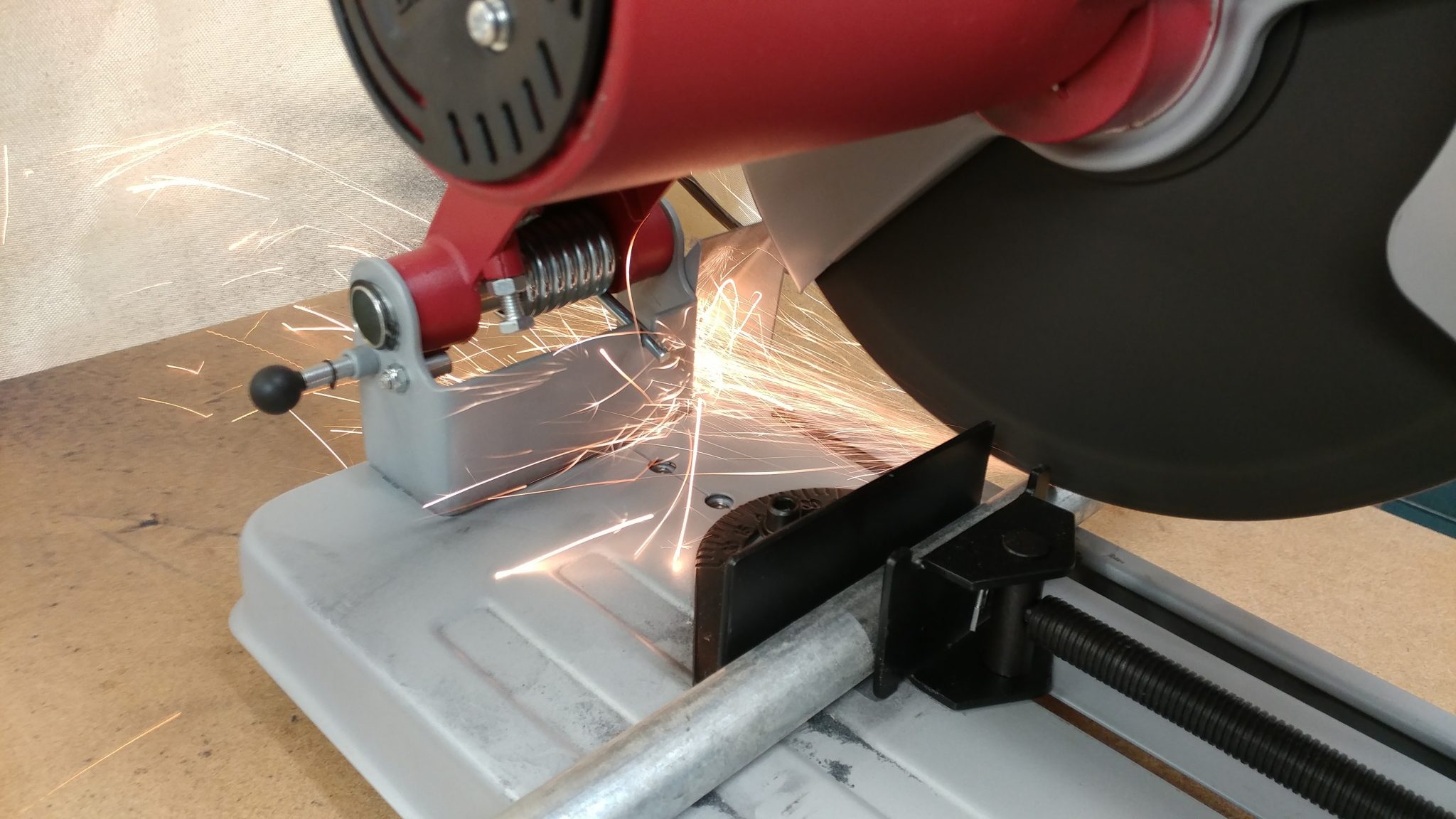
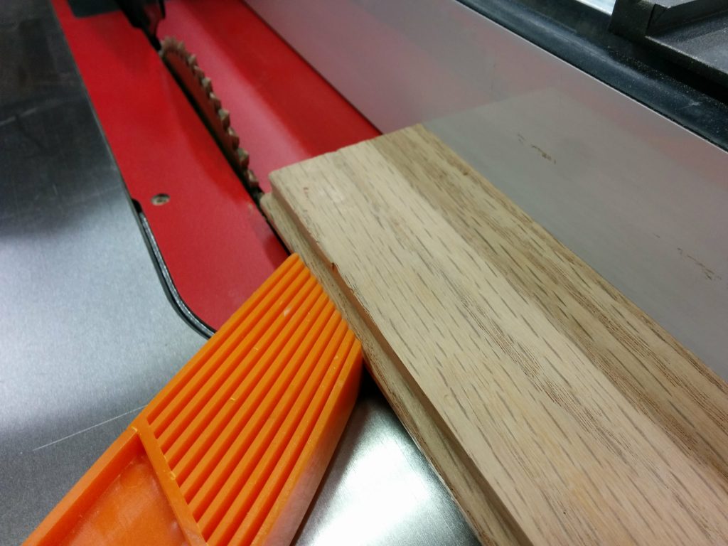
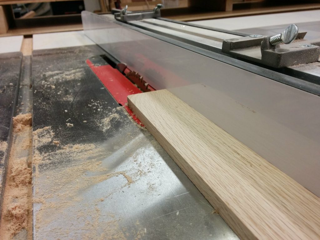
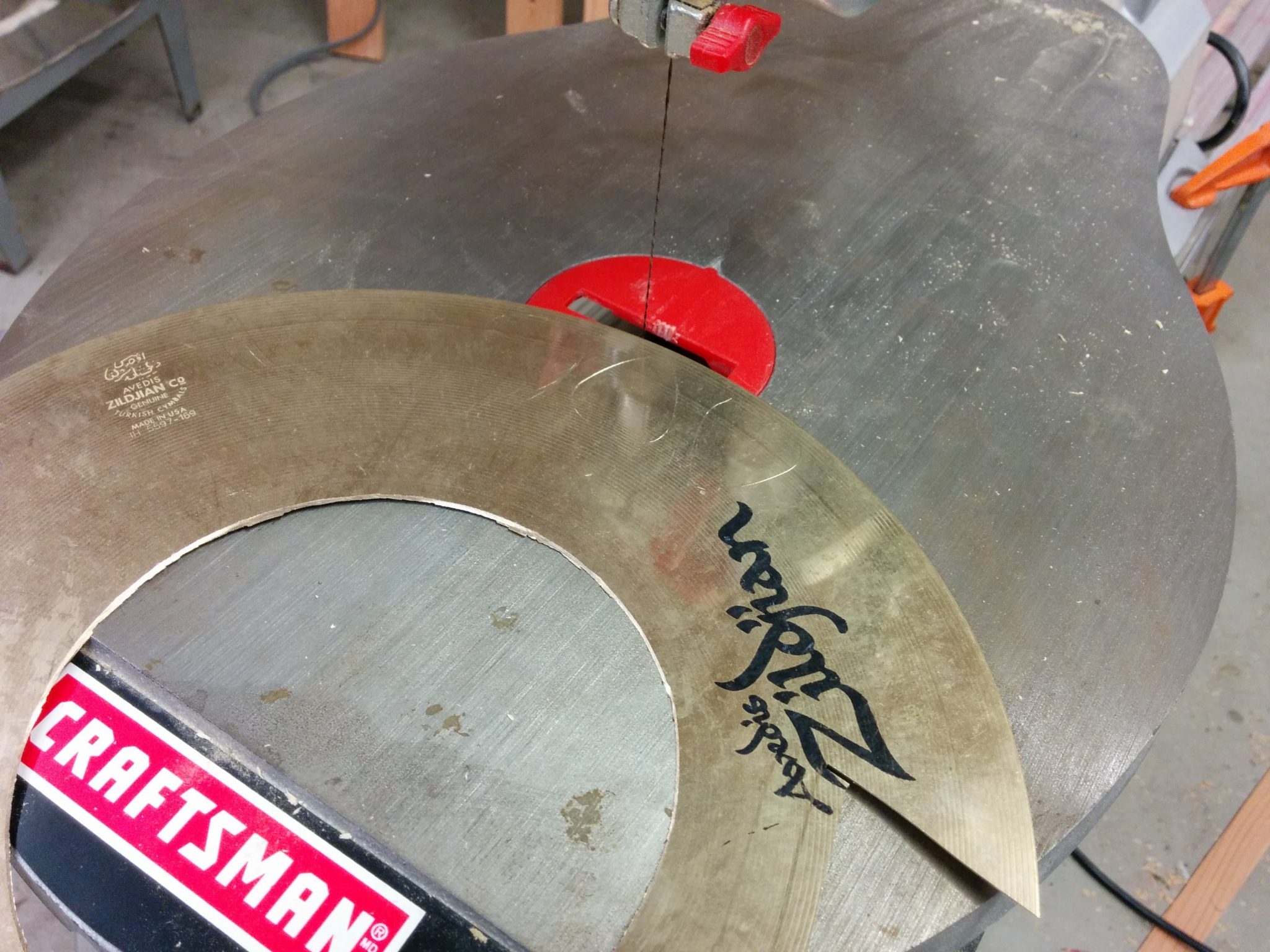
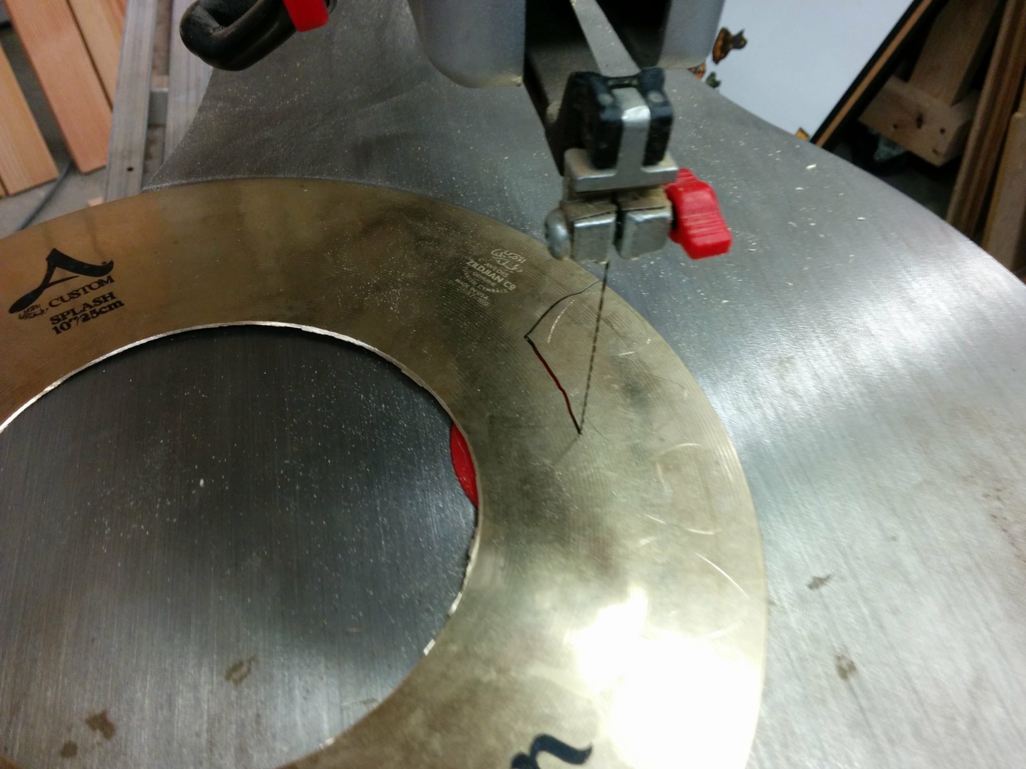
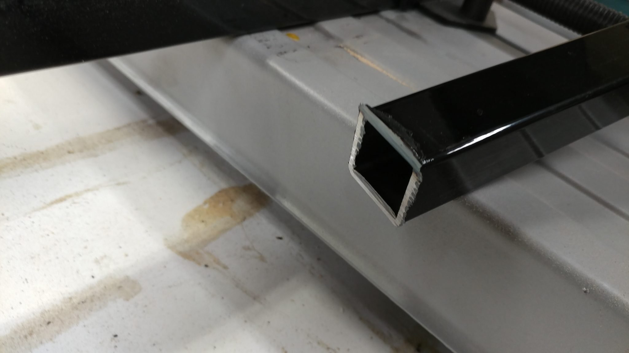
I used my chop saw to cut along that line.
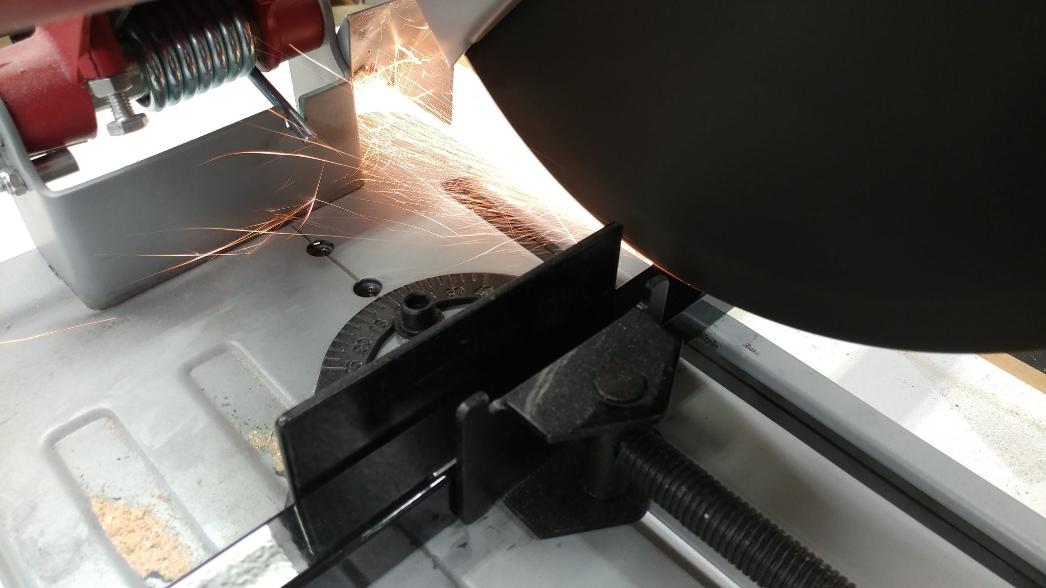
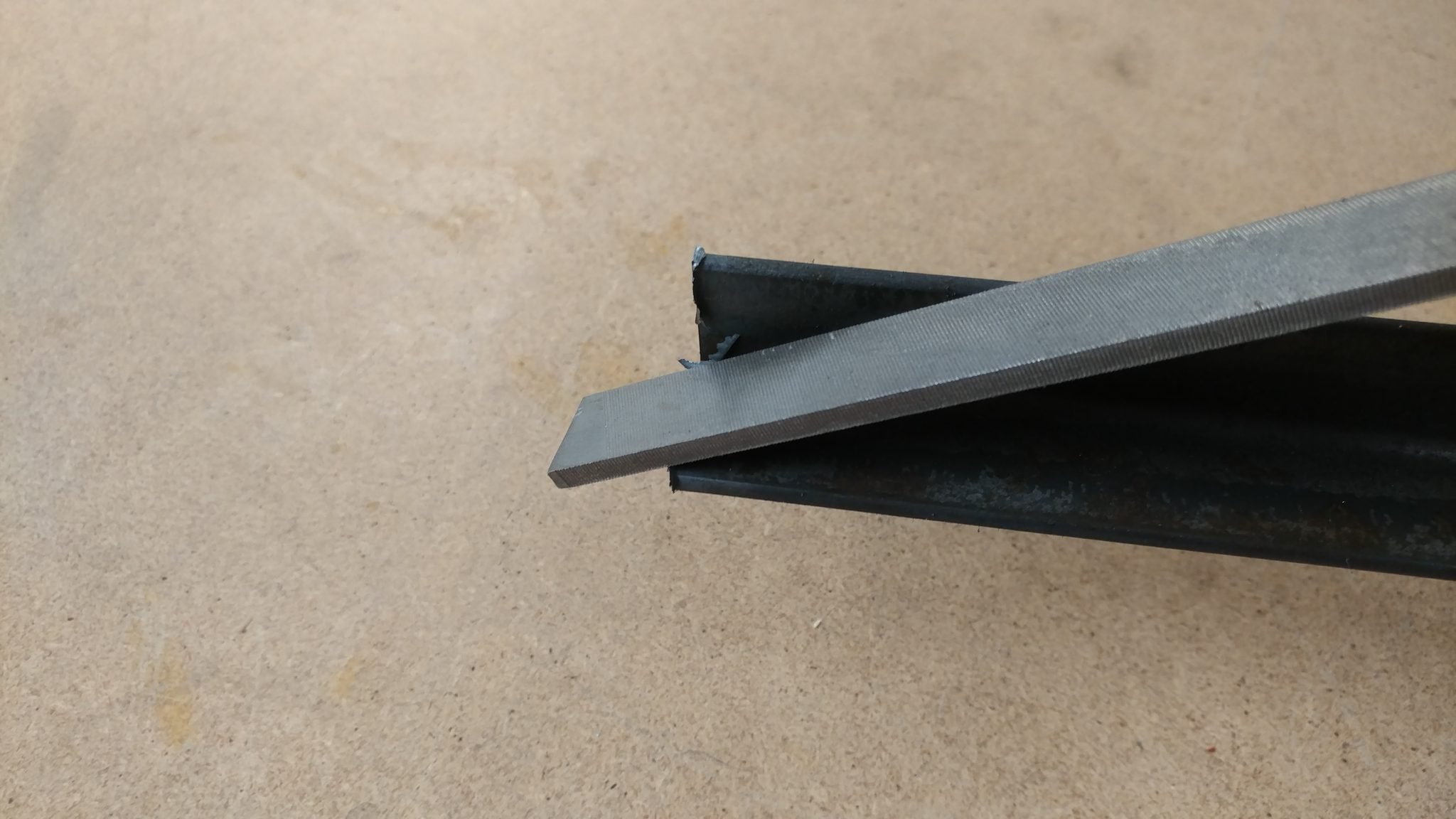
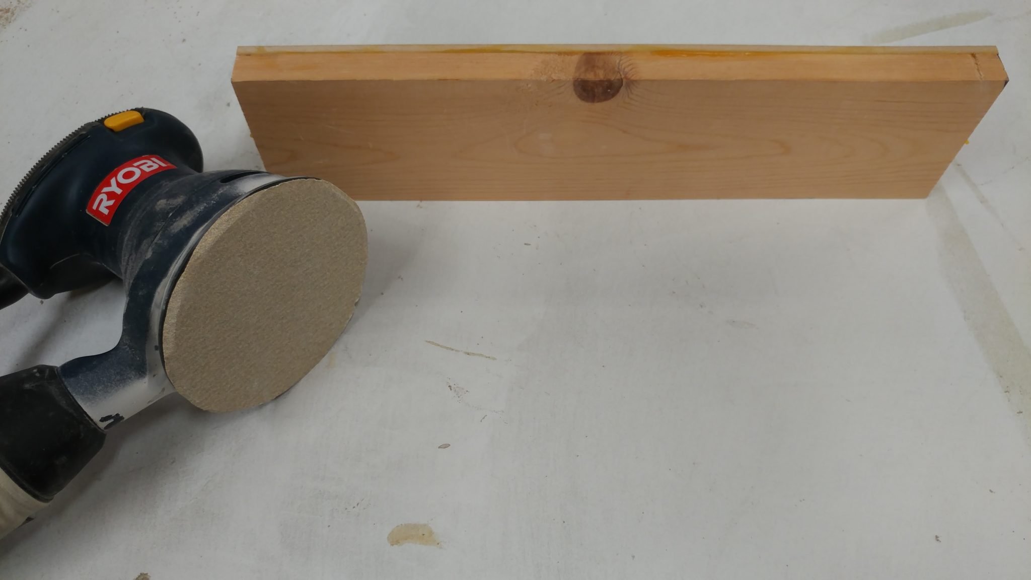
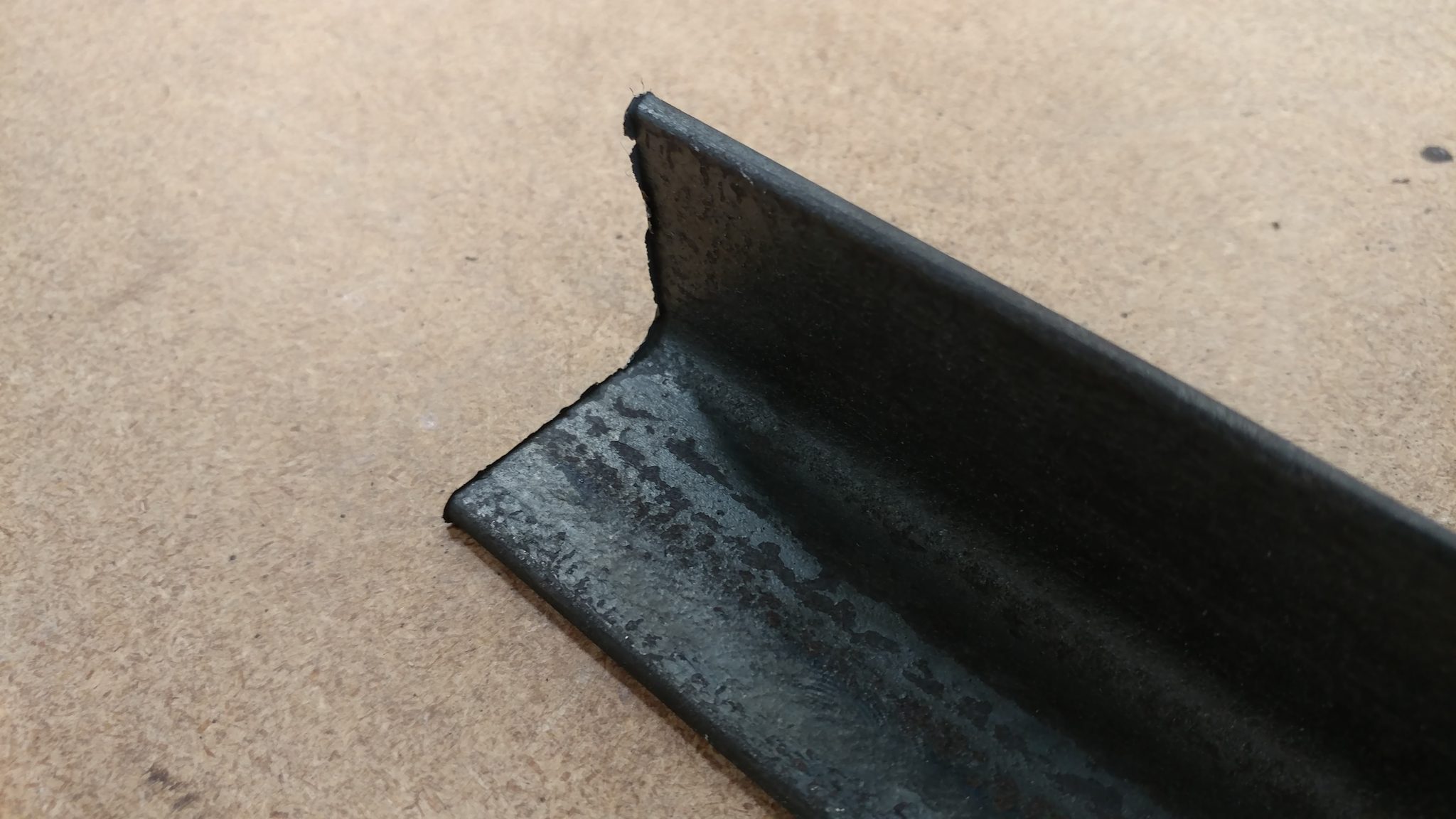
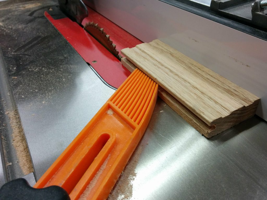
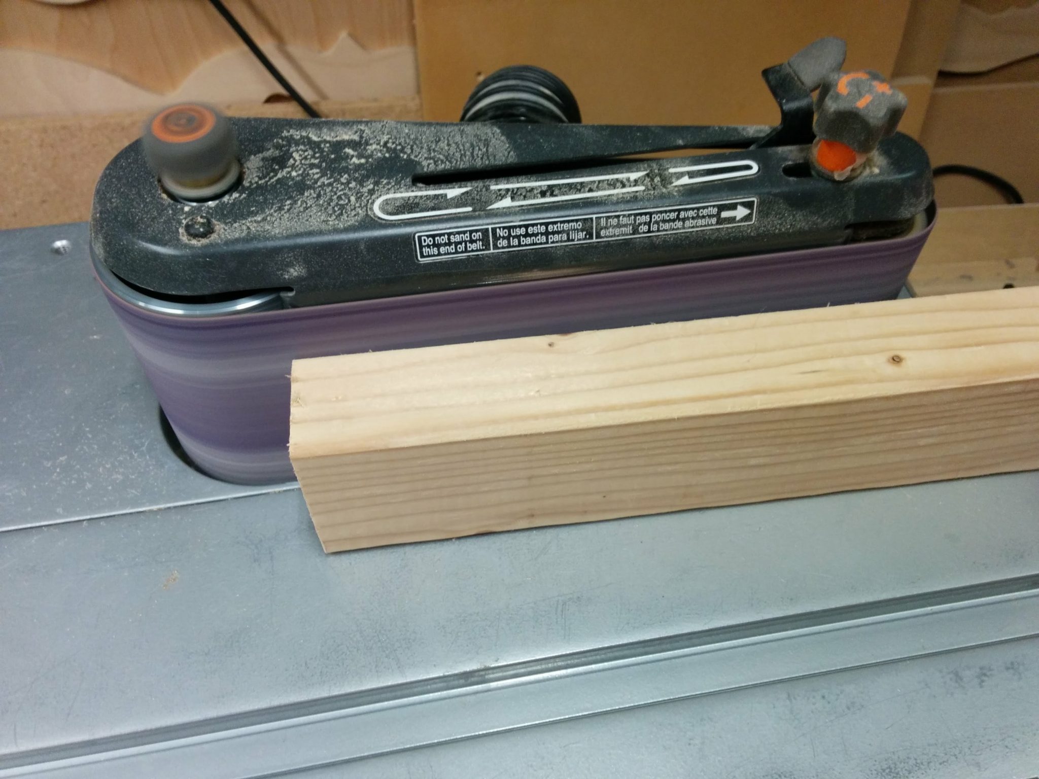
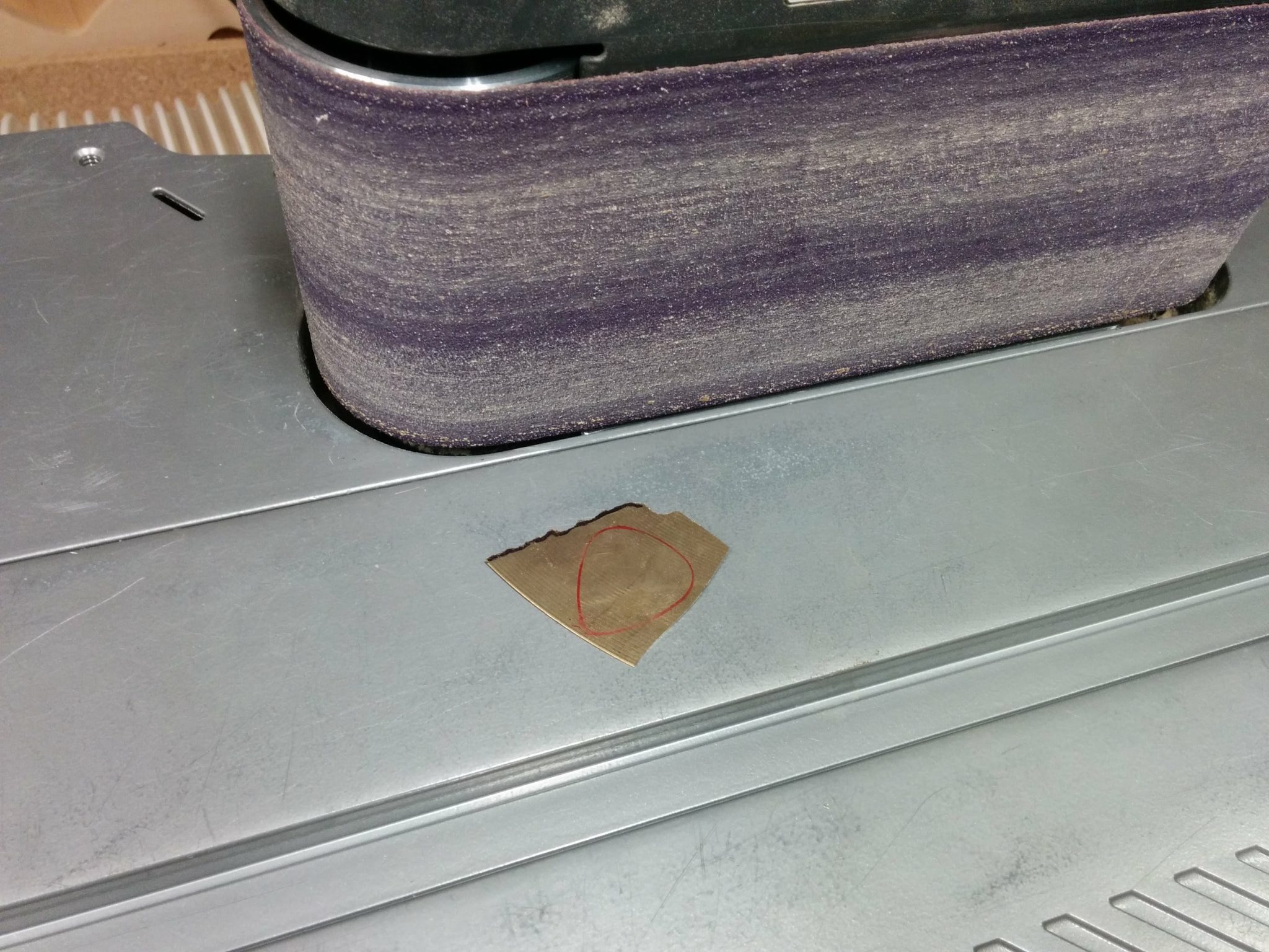
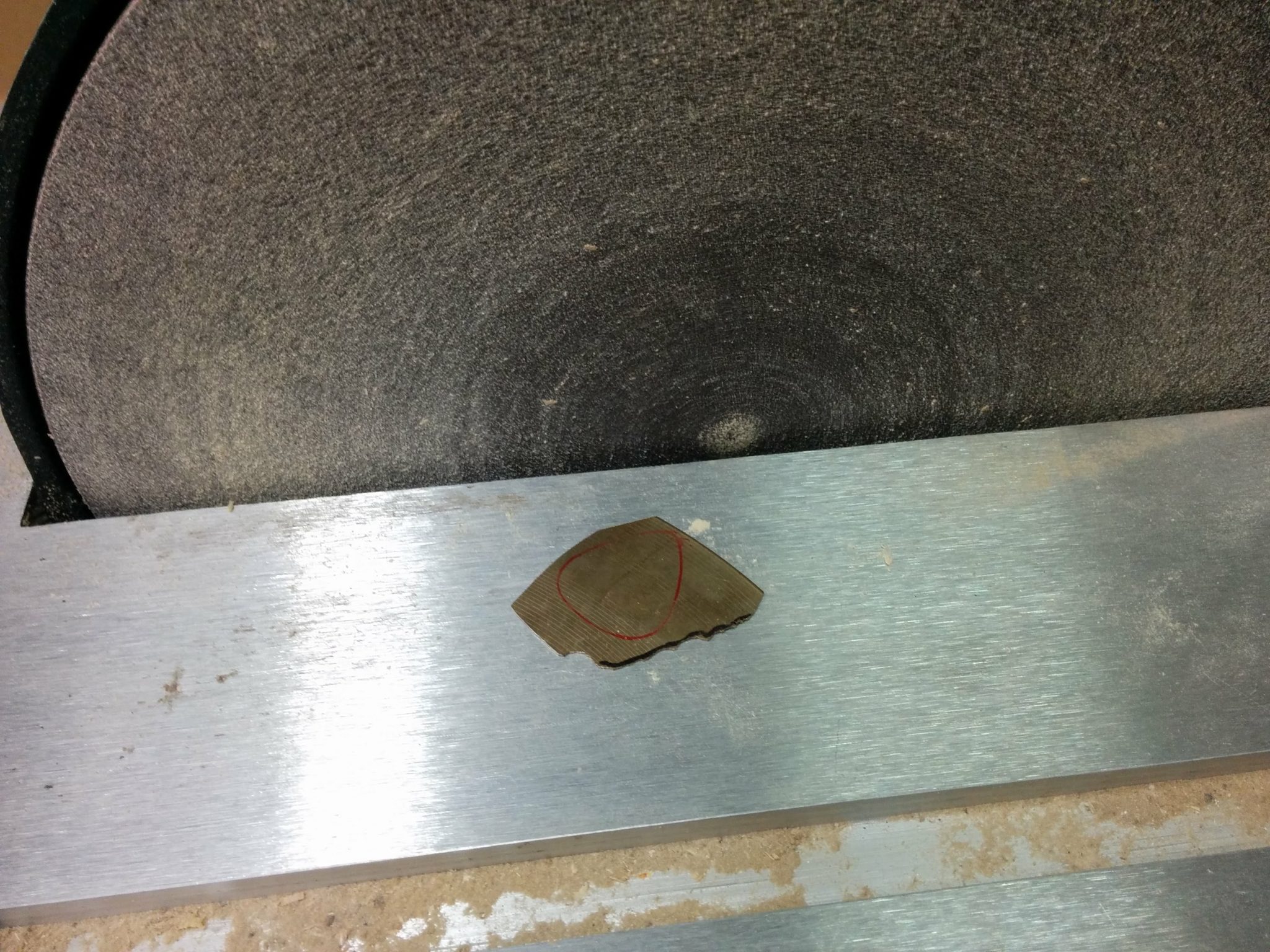
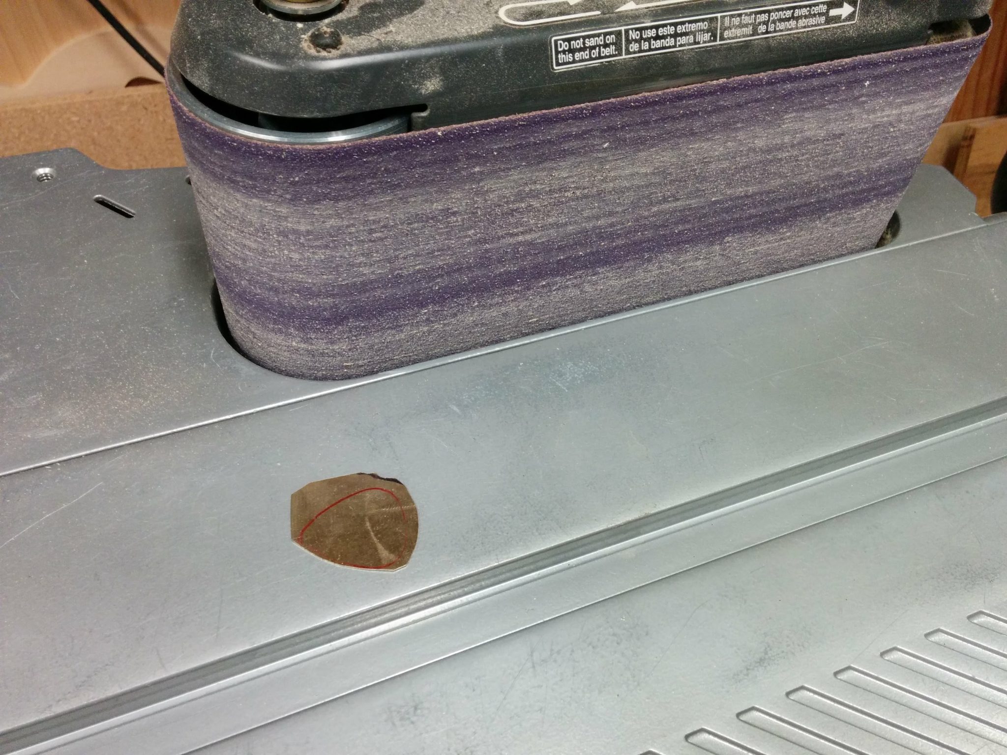
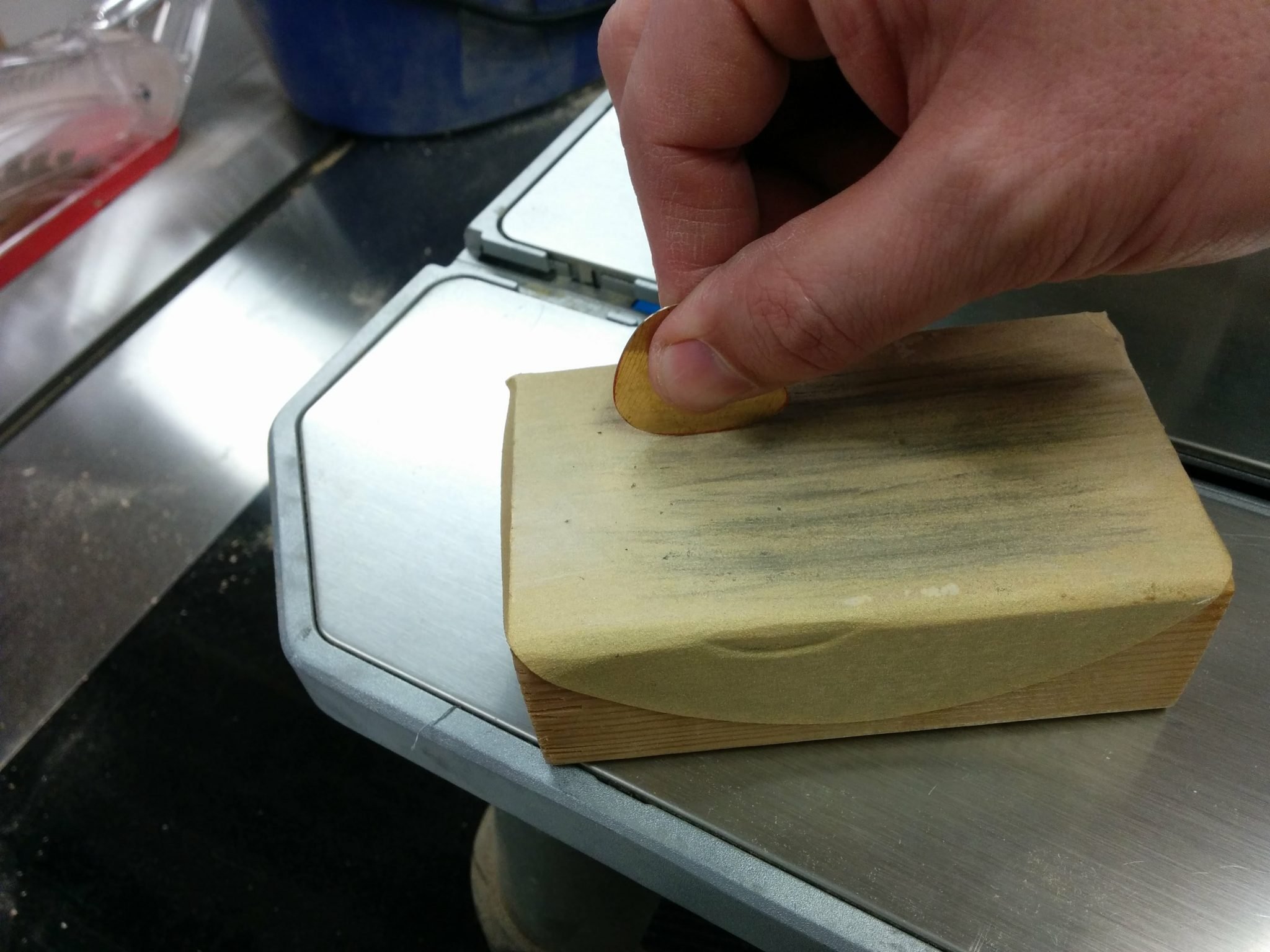
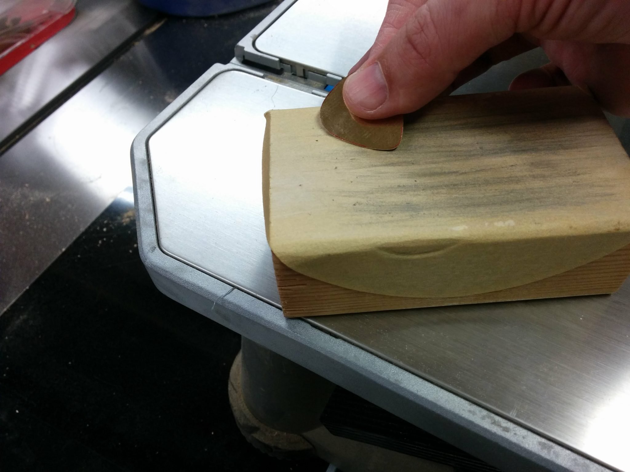
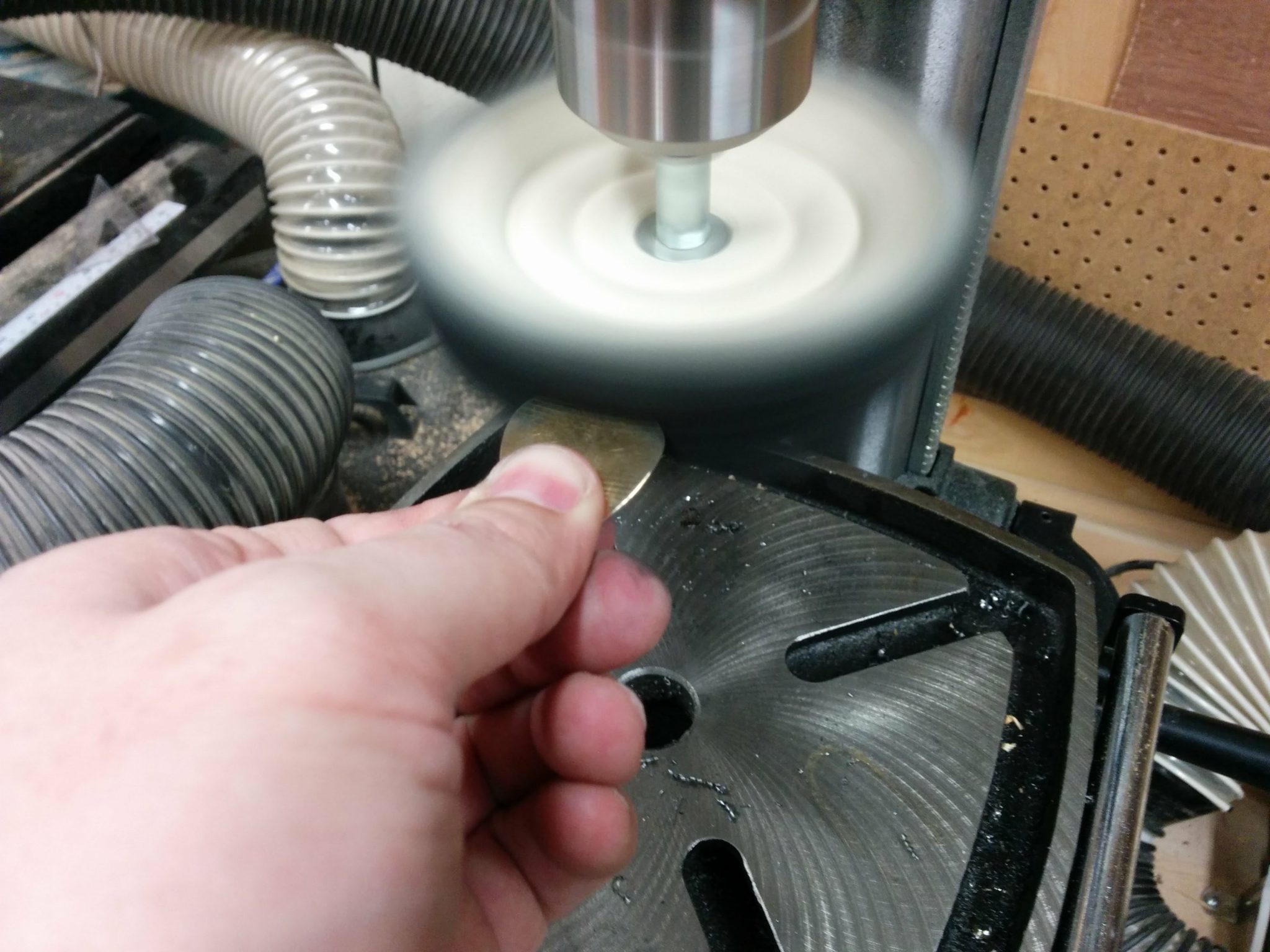
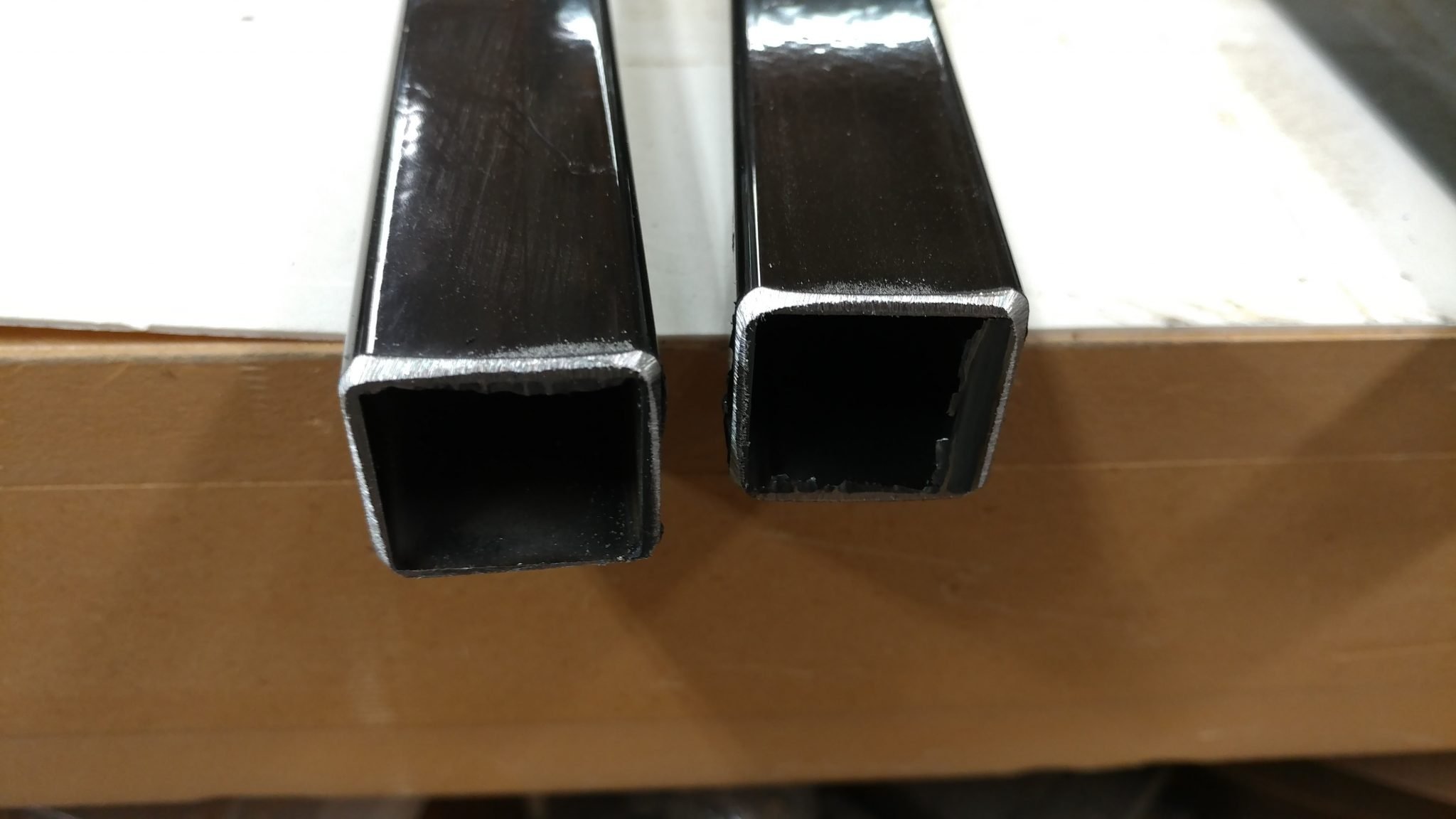
The chop saw leaves a pretty nasty burr that I will want to remove.
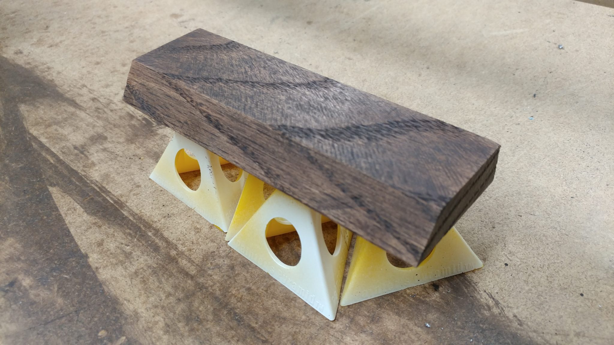
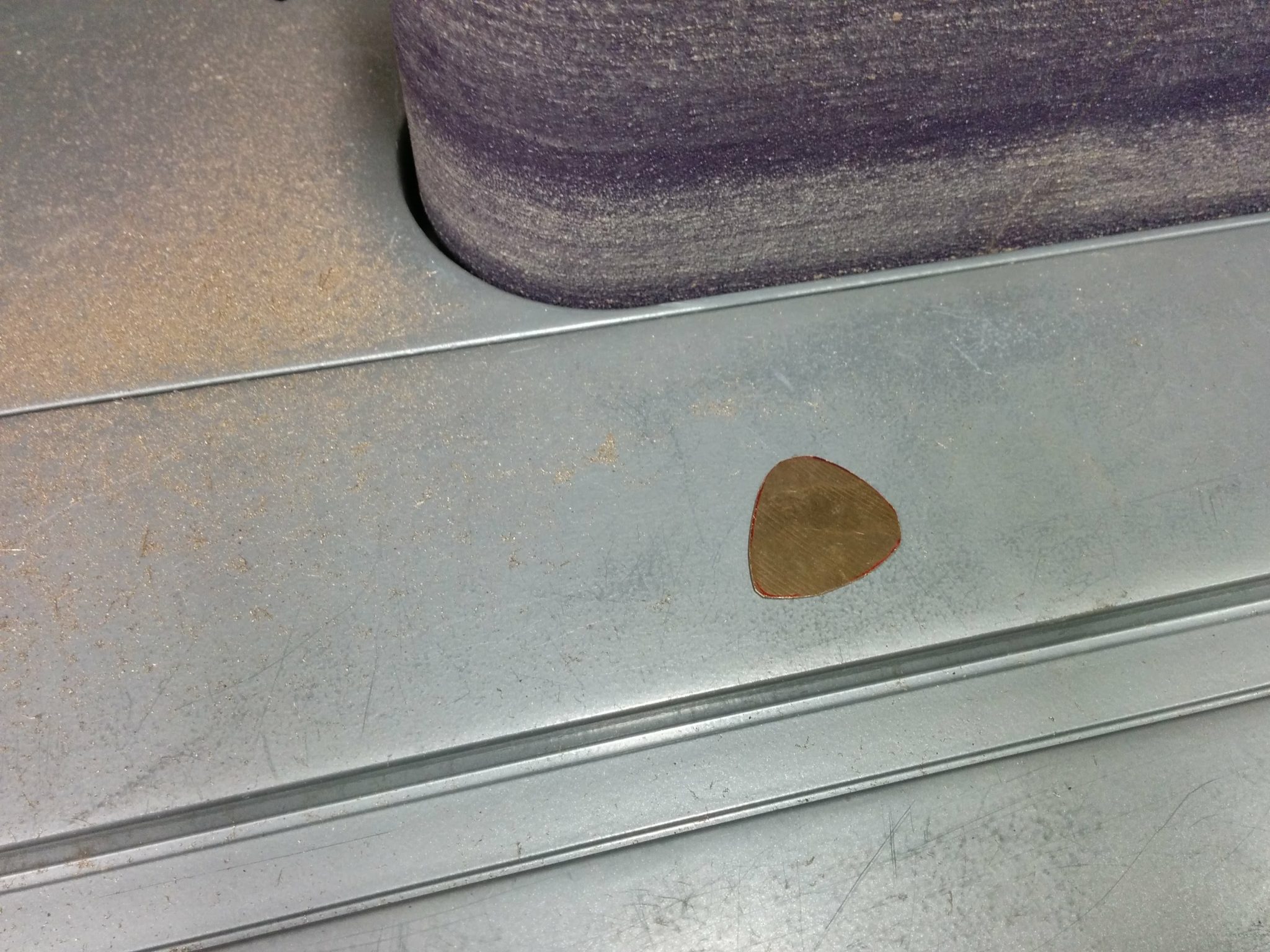
A few seconds at the disc sander quickly rounded over the edges enough to remove the burr.
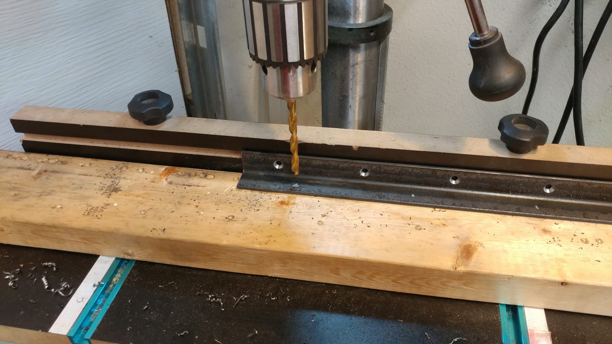
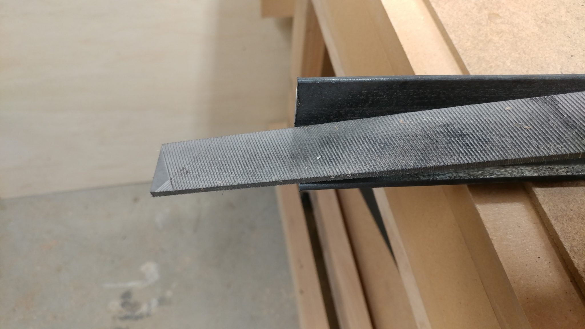
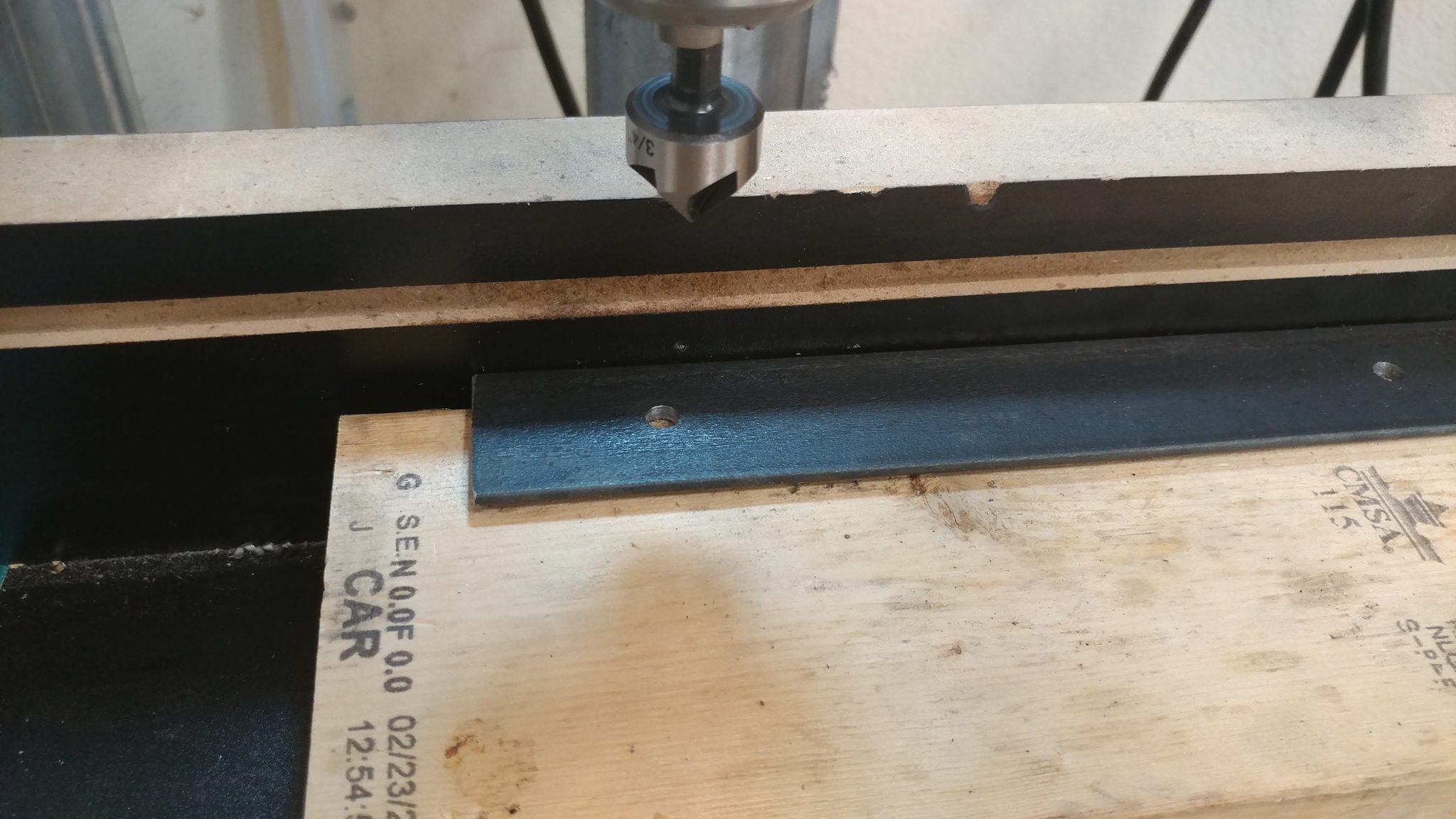
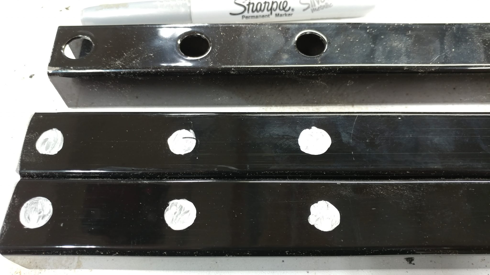
I use the discarded upper end of the leg and a silver Sharpie to mark where I will need to drill.
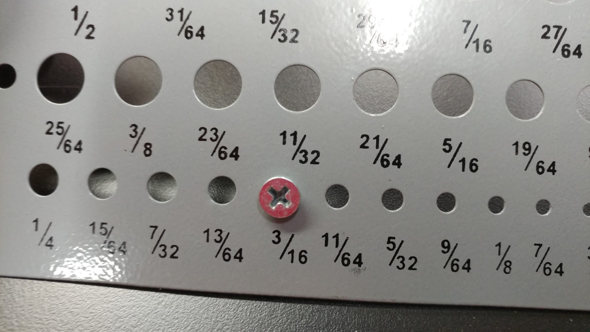
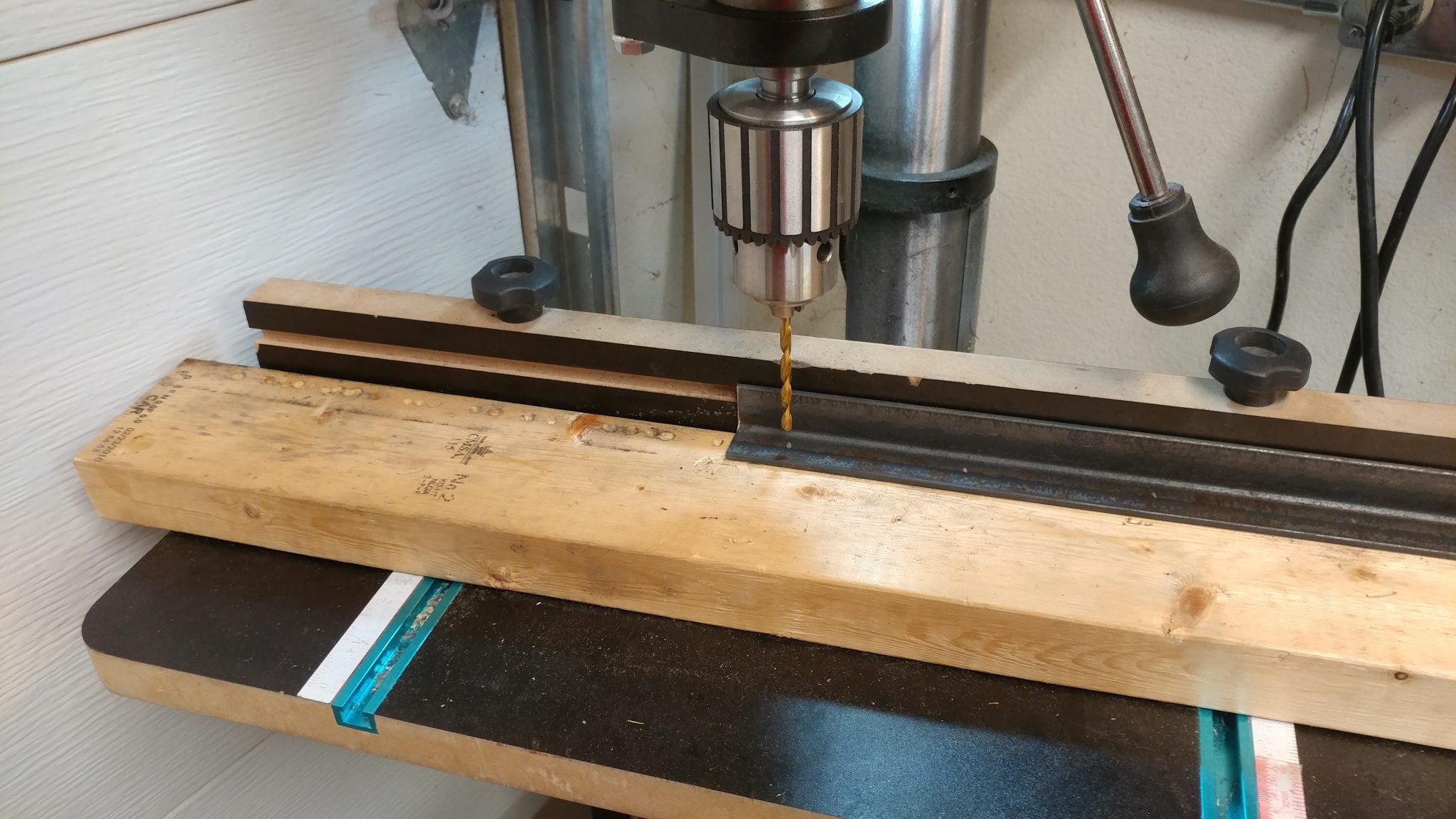
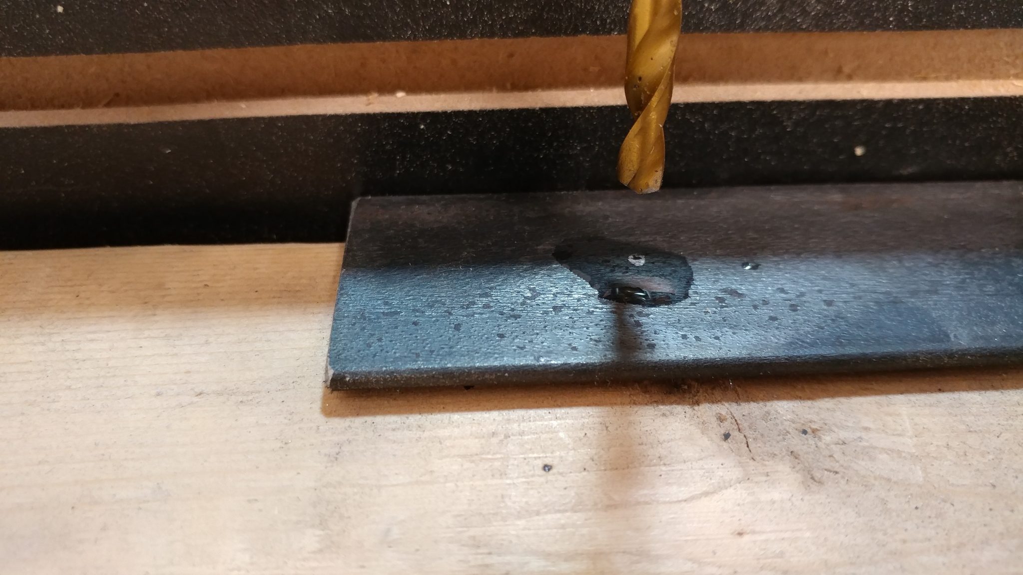
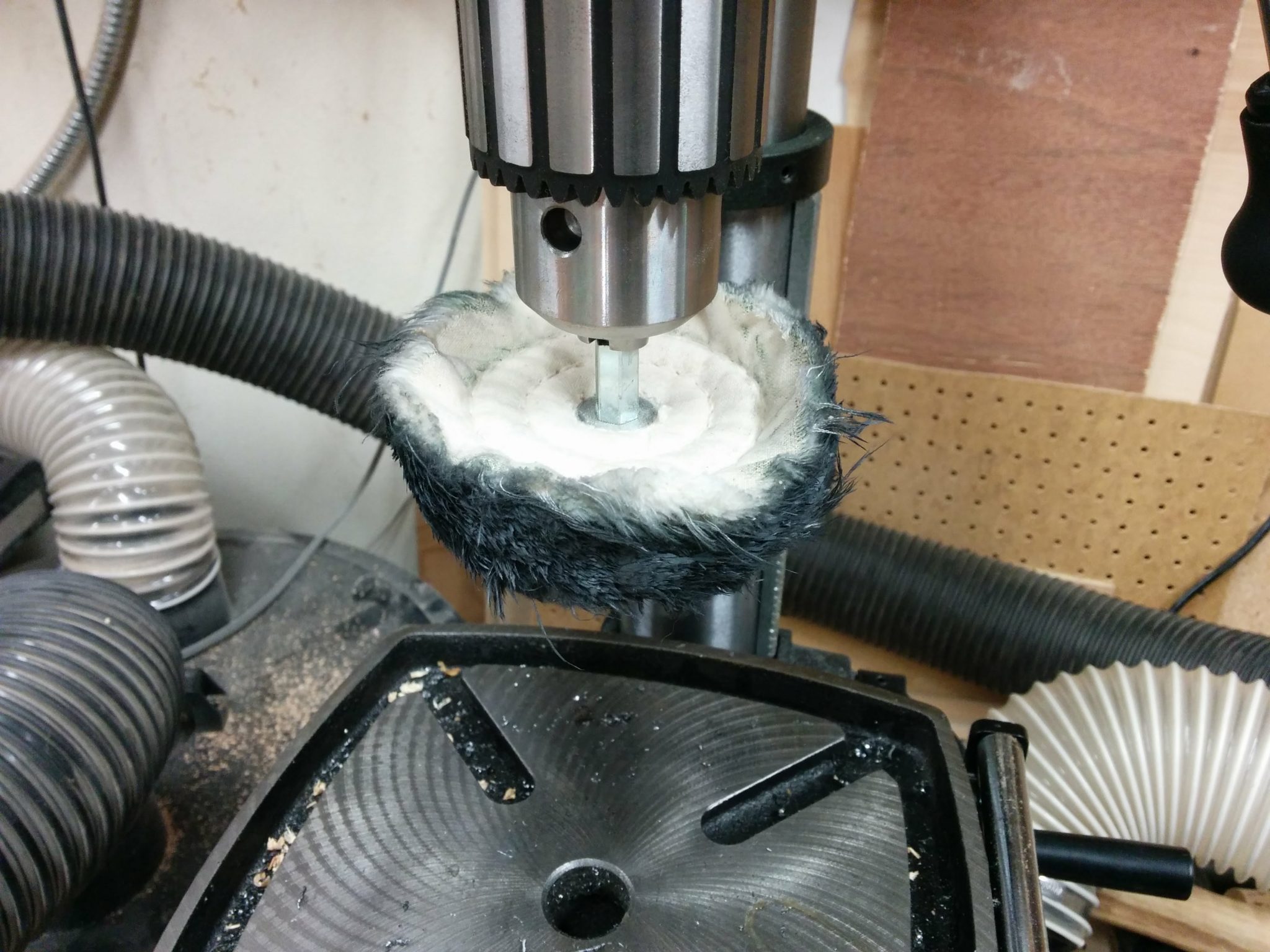
I used my drill press and some 3-in-1 oil to drill out those holes.
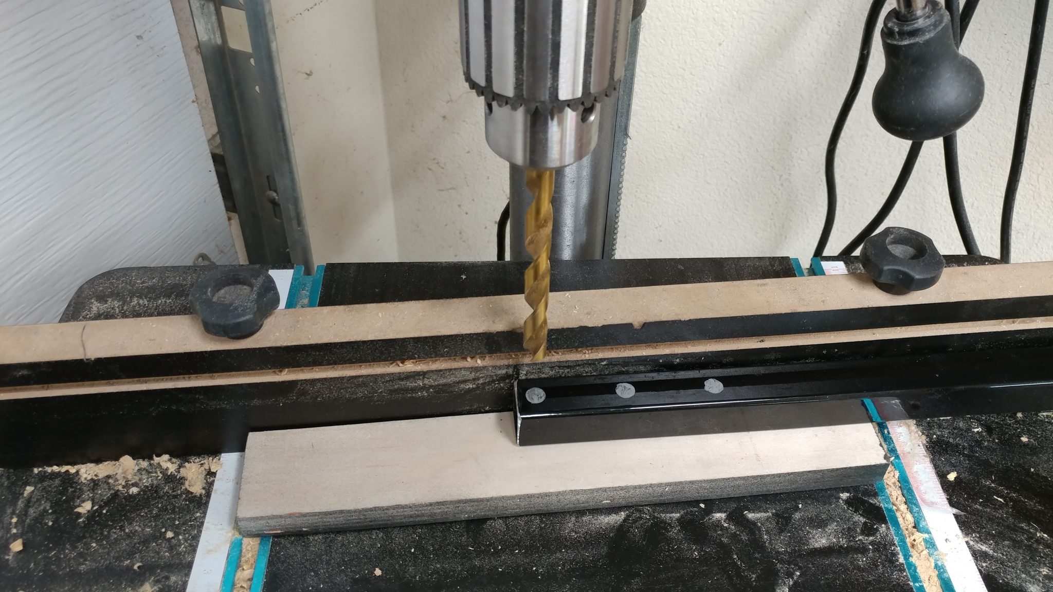
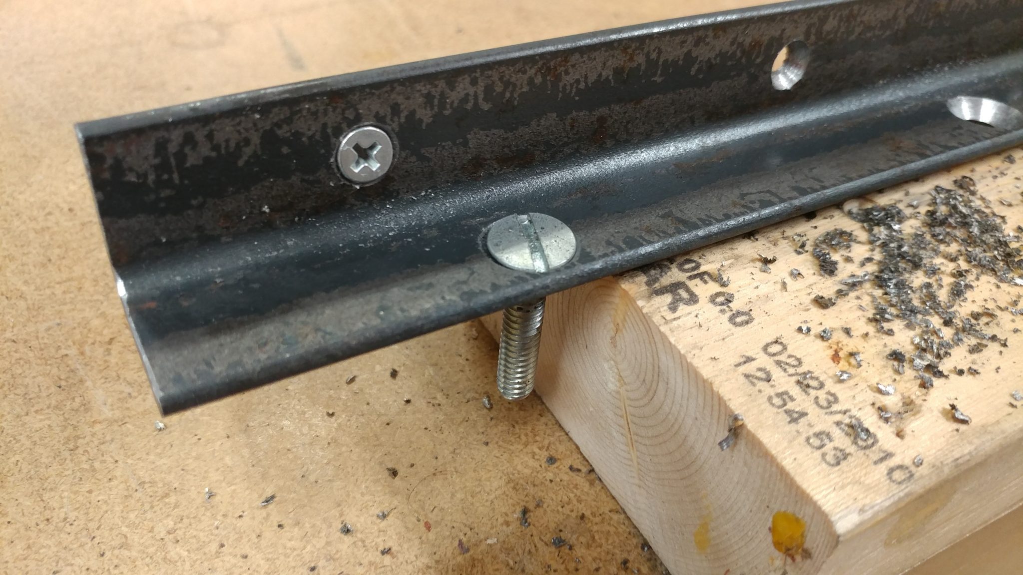
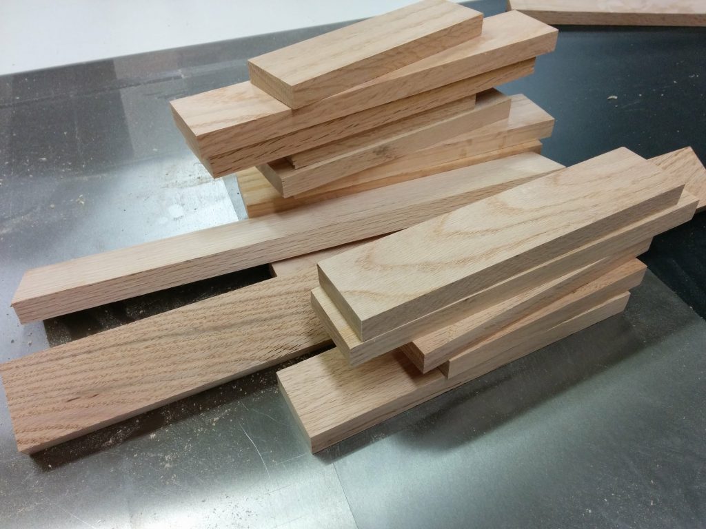
The just need to be cleaned up a bit and they’re ready to use.
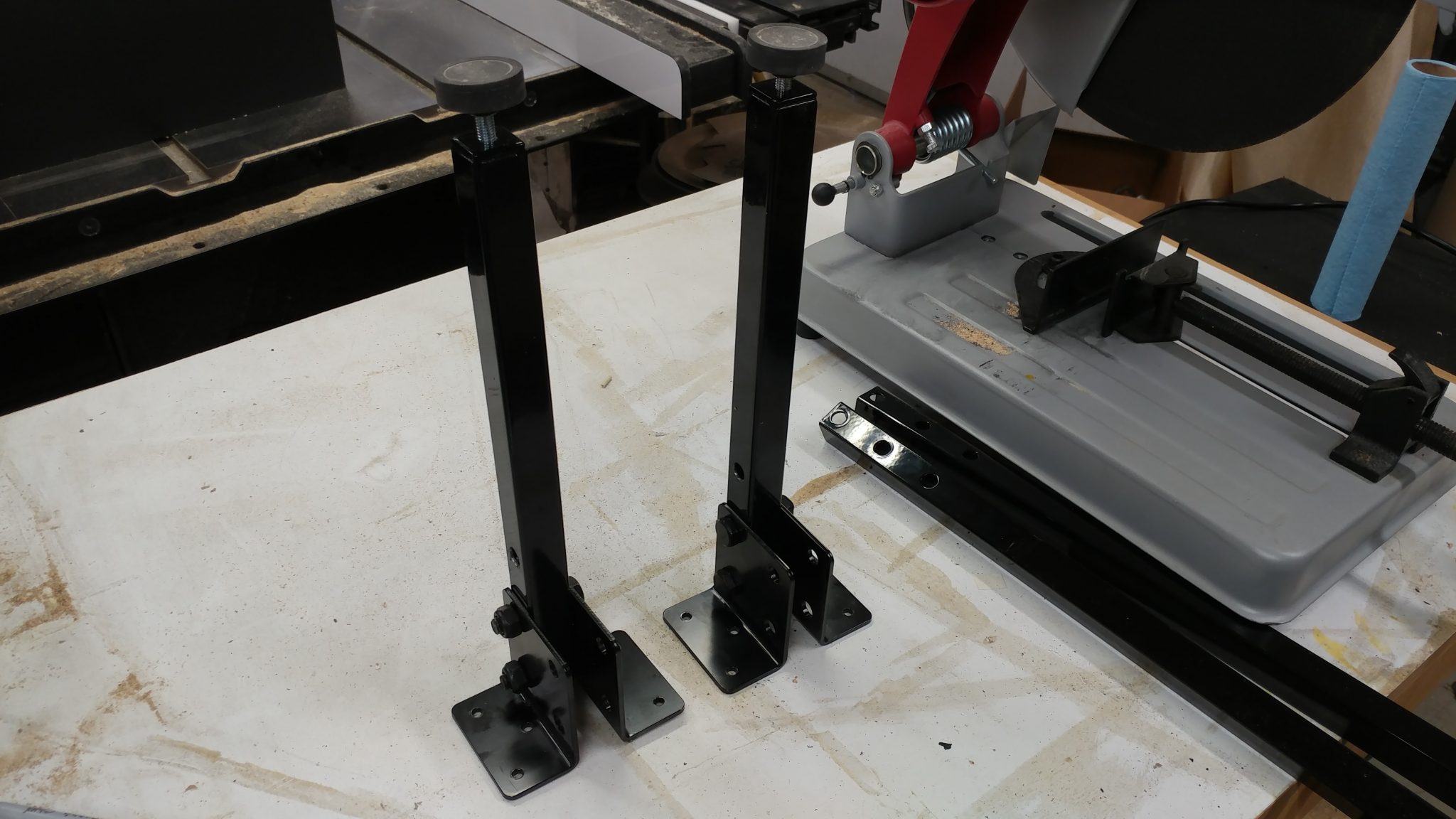
I reattached the hardware and now I have some mini-legs. Ain’t they cute?
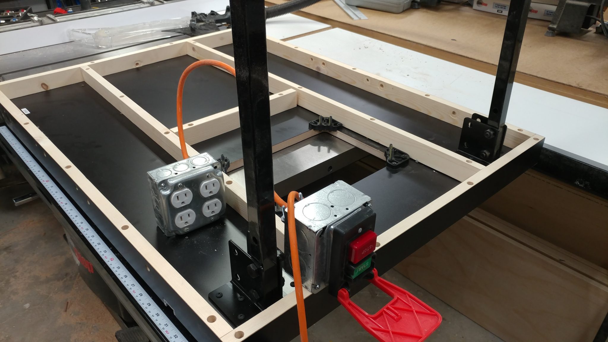
Attaching the cabinet to the table
Time to finish this up.
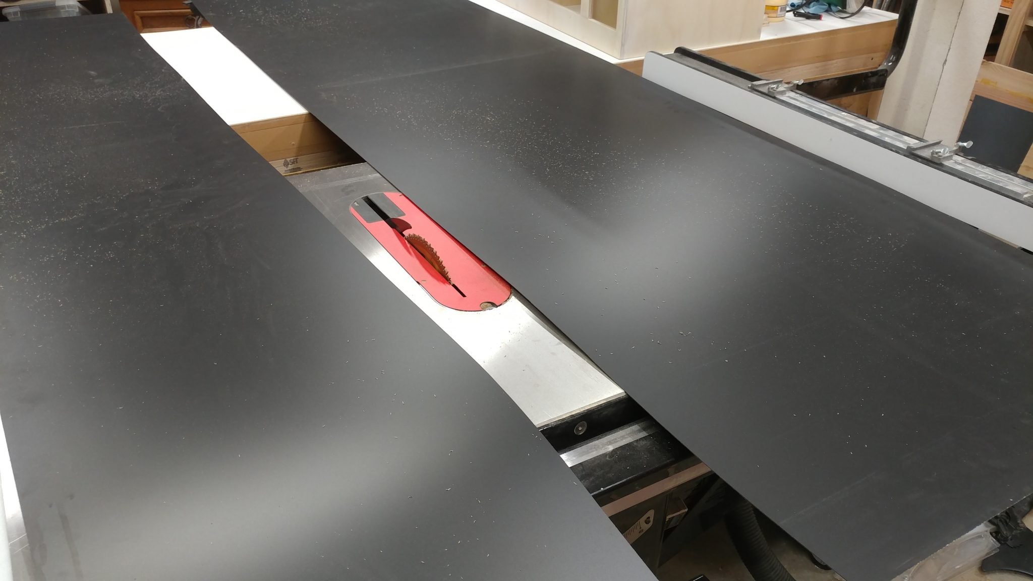
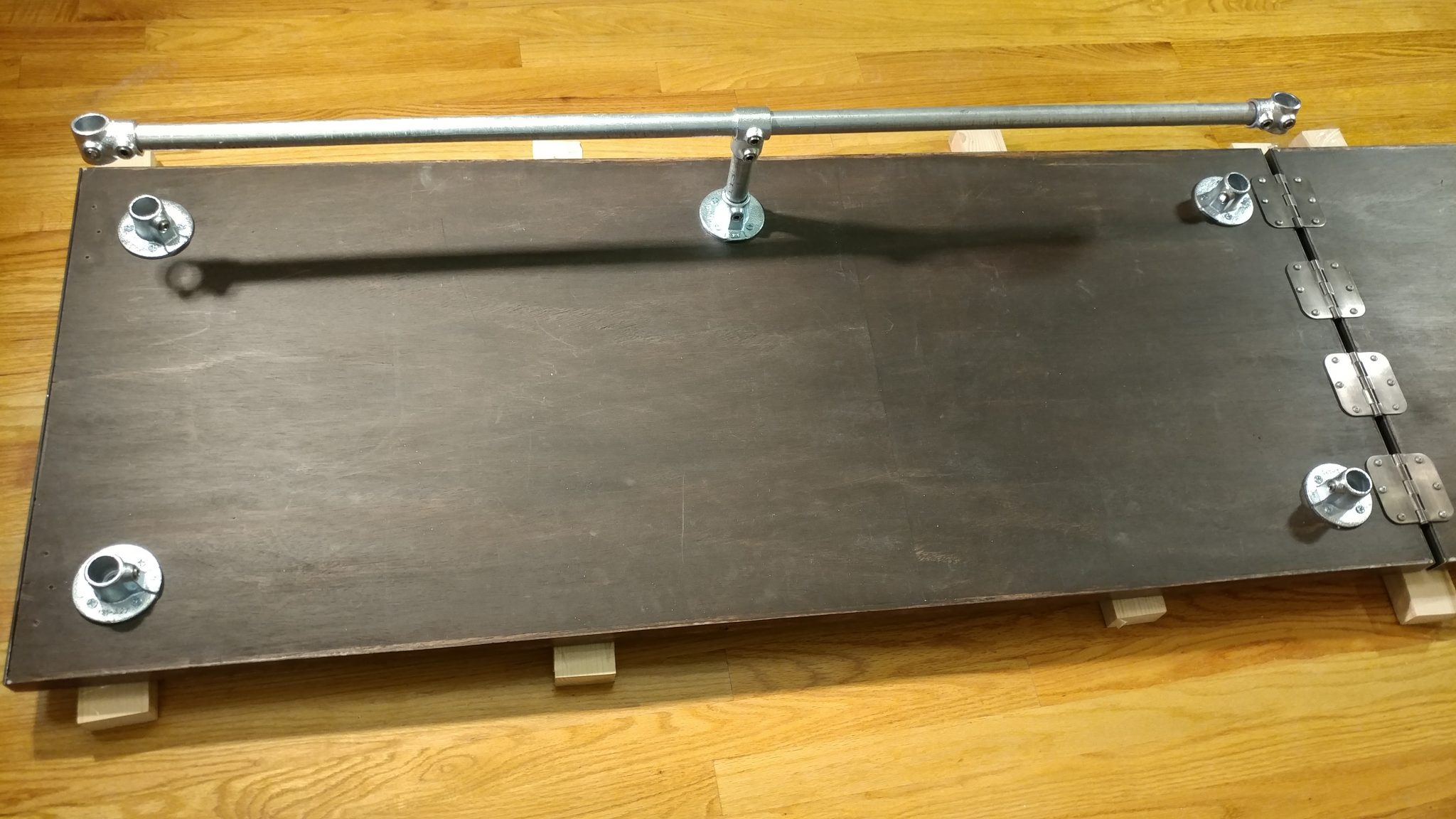
I start by turning my extension table upside-down.
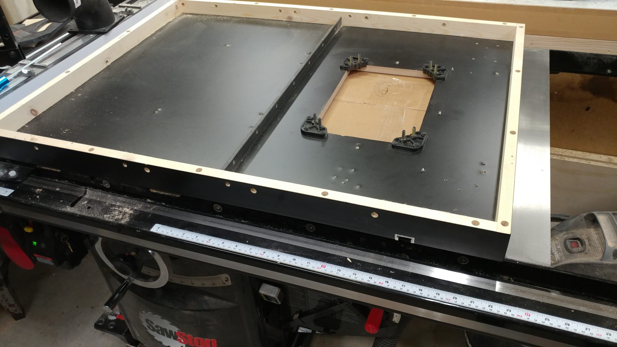
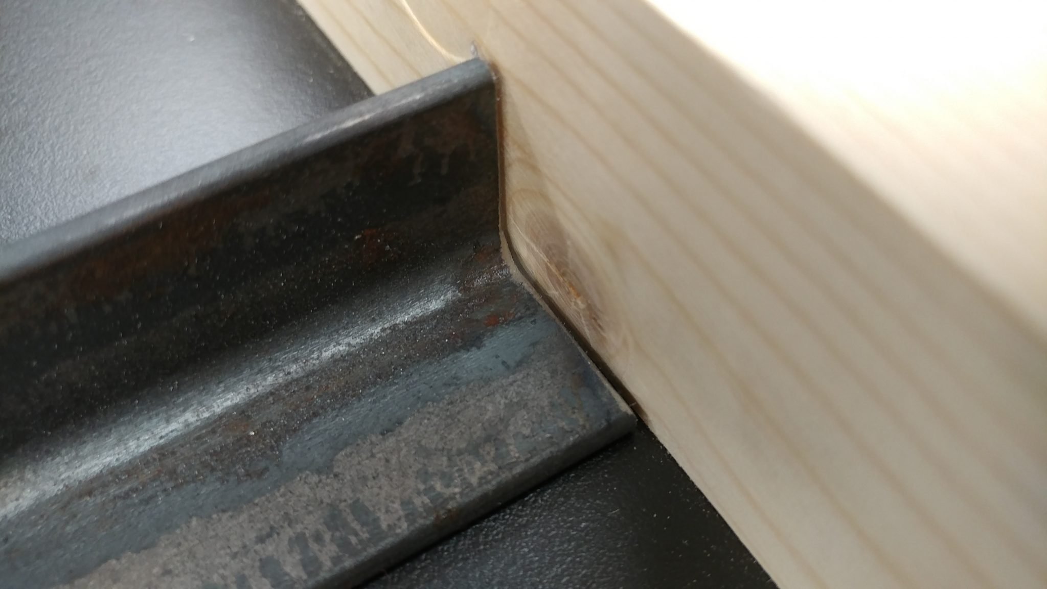
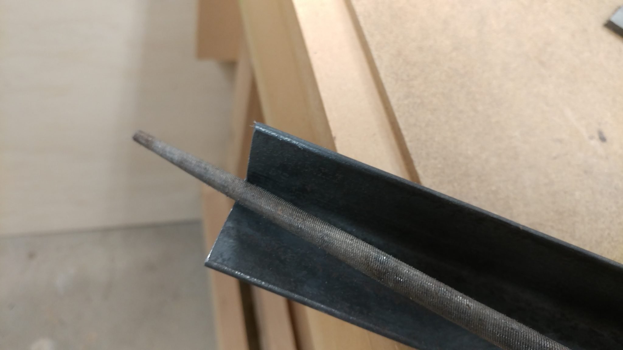
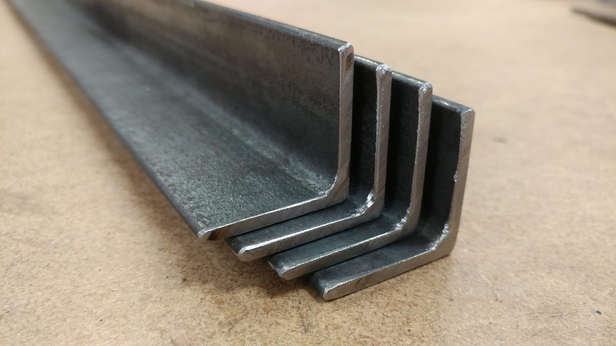
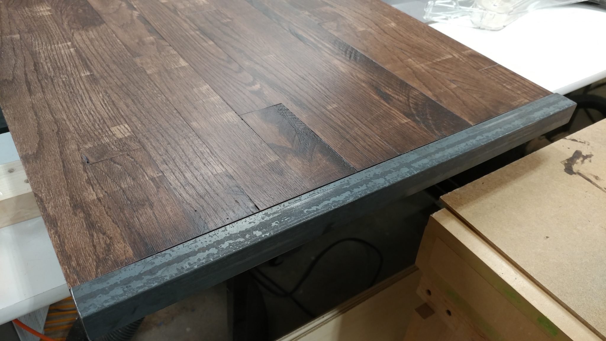
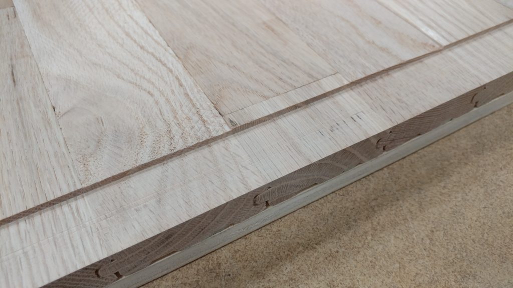
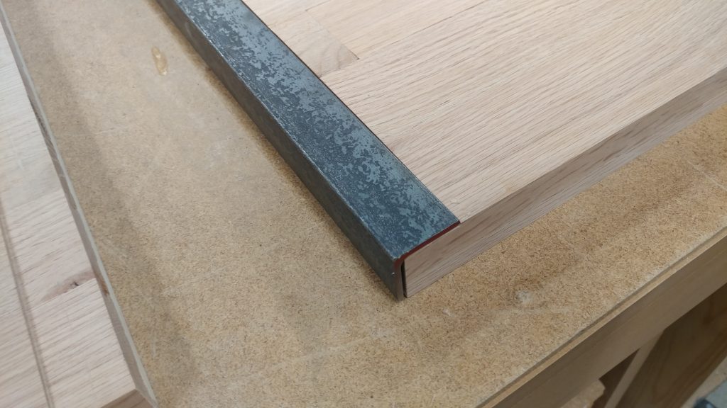
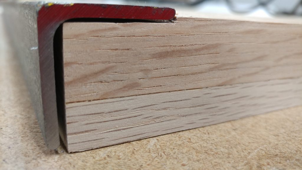
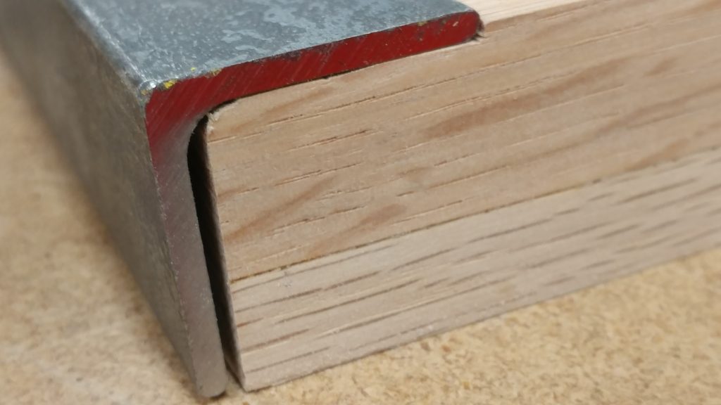
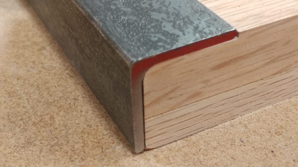
The router enclosure fits in-between the angle iron I attached earlier and the end of the actual table.
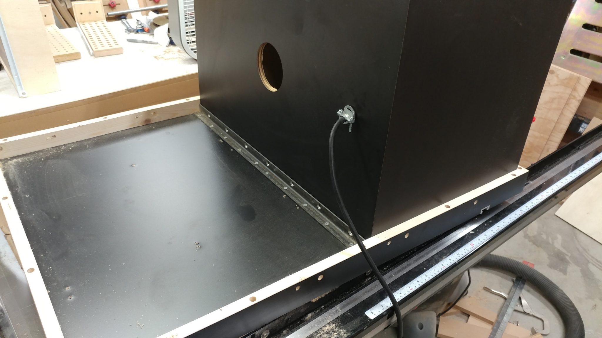
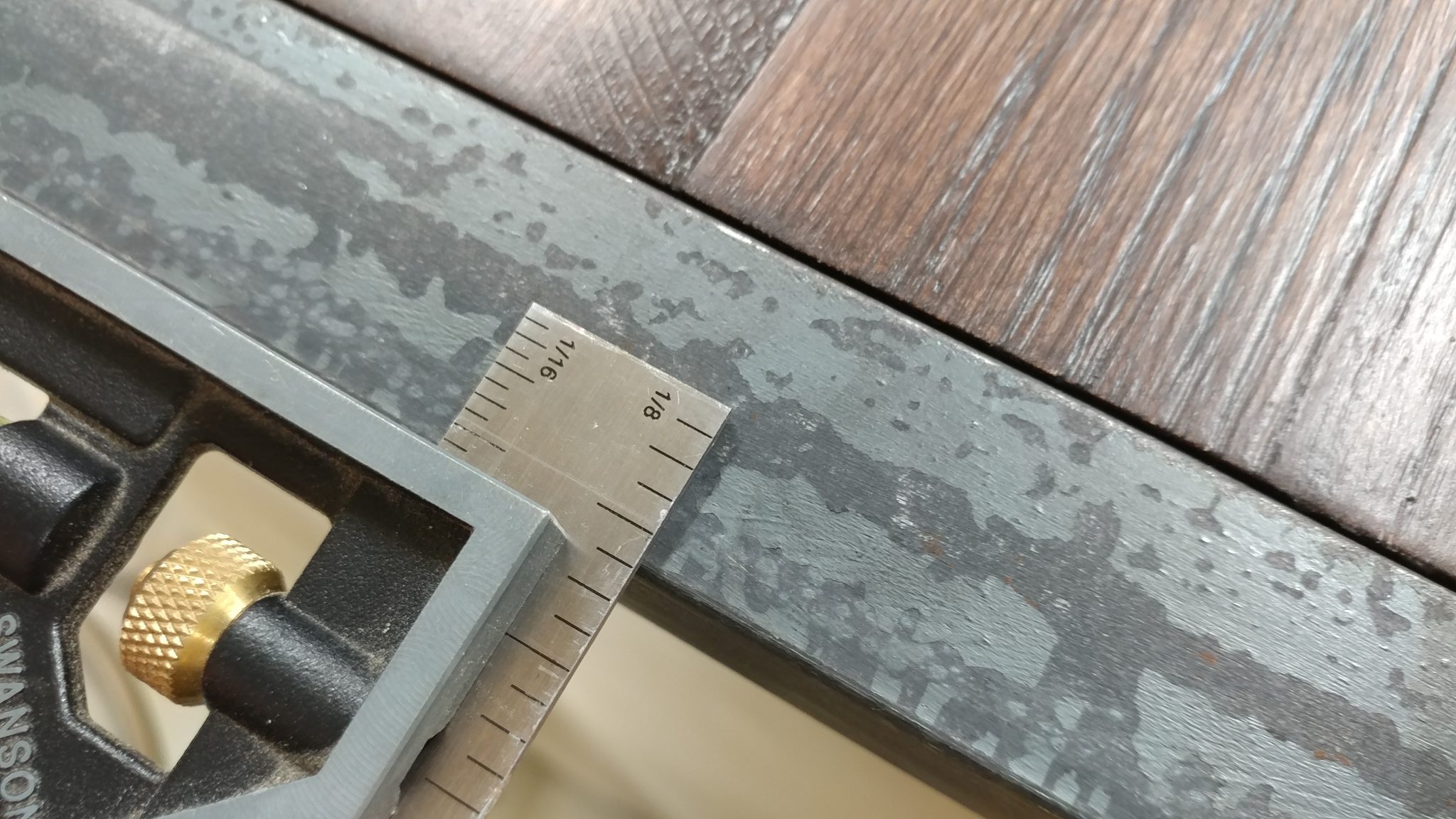
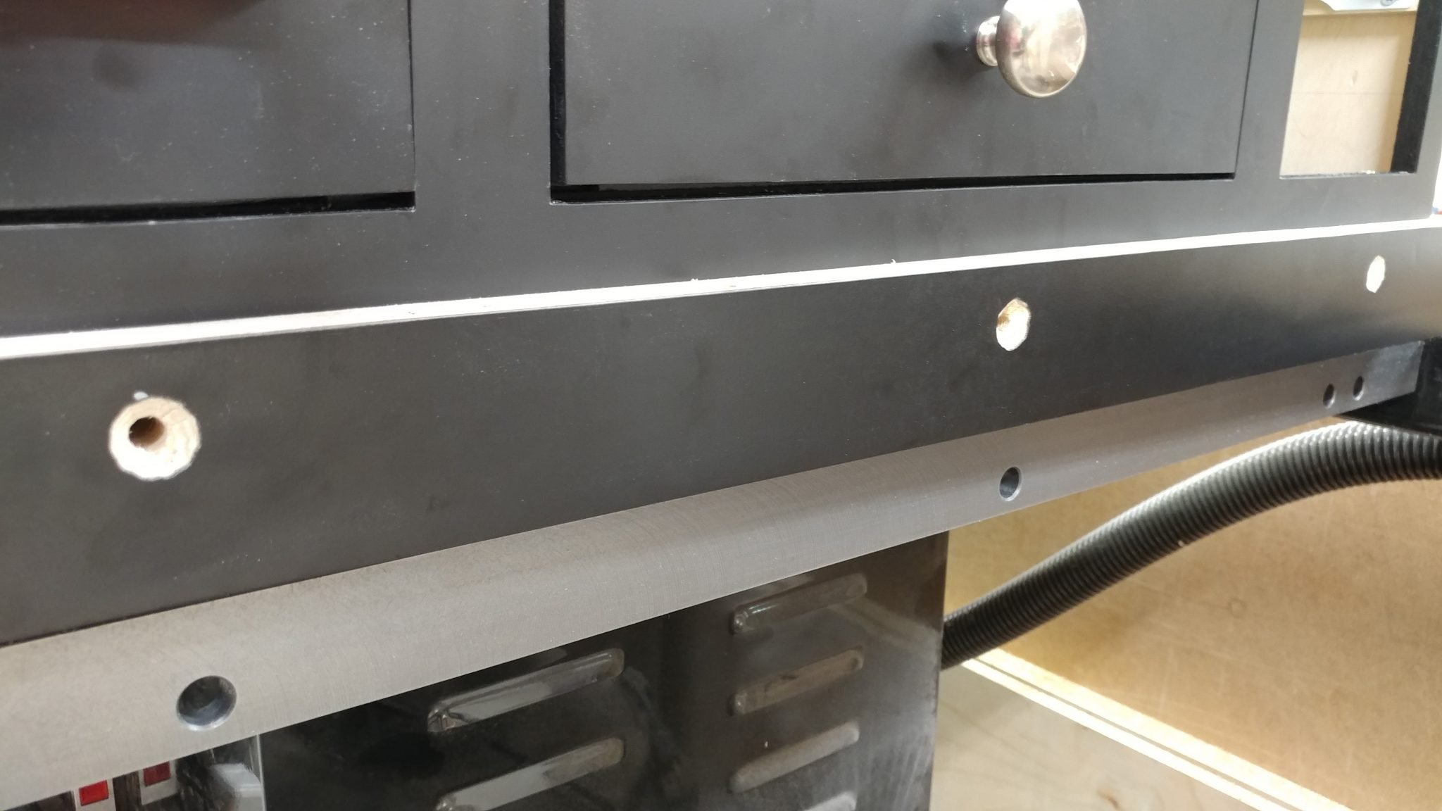
I need to mark and drill the holes for the screws that will attach the enclosure to the angle-iron.
I used a silver Sharpie to mark these holes.
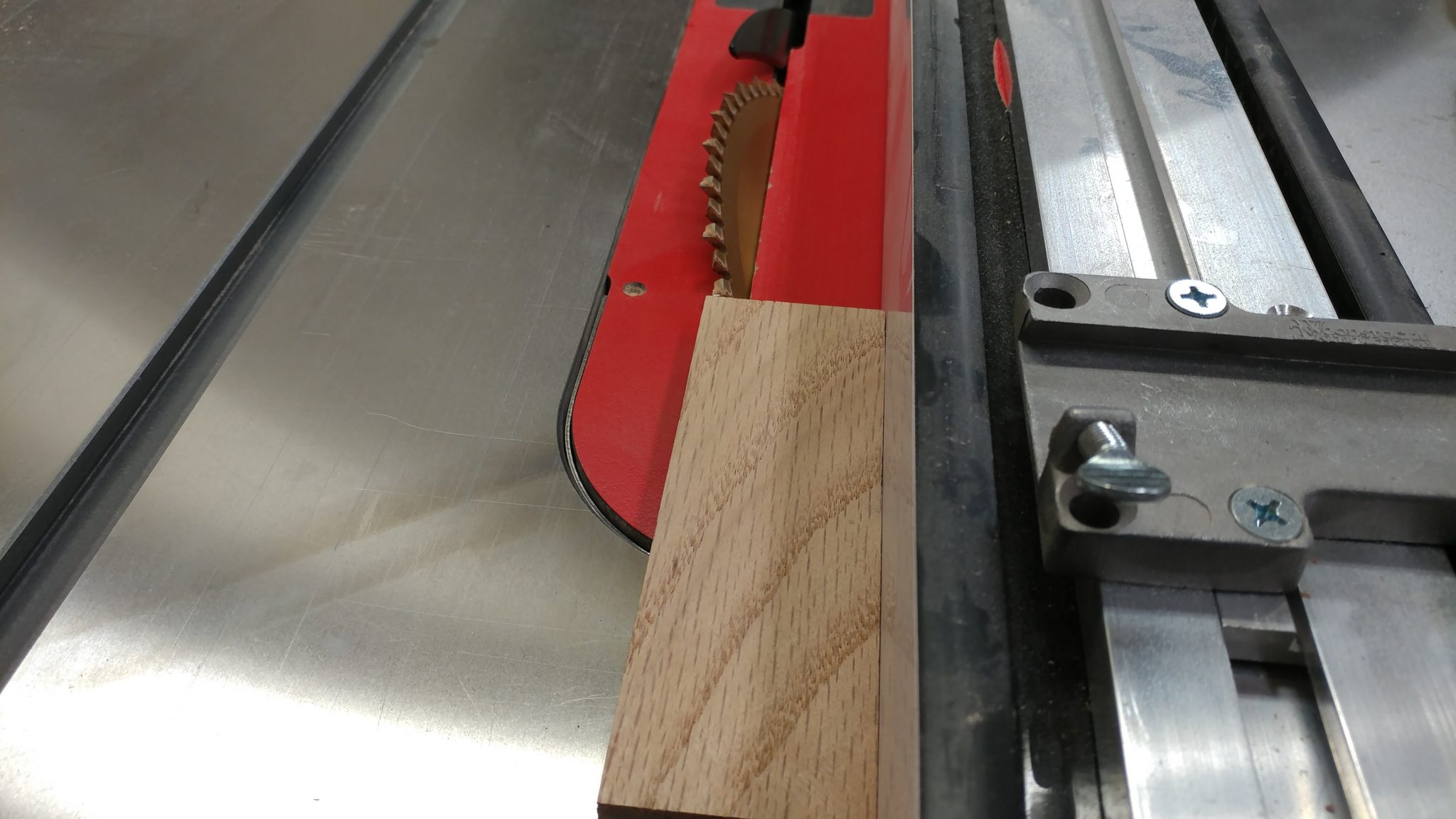
I also marked the holes on the side where the screws will go through the front rail on the table saw, the table, and the enclosure.
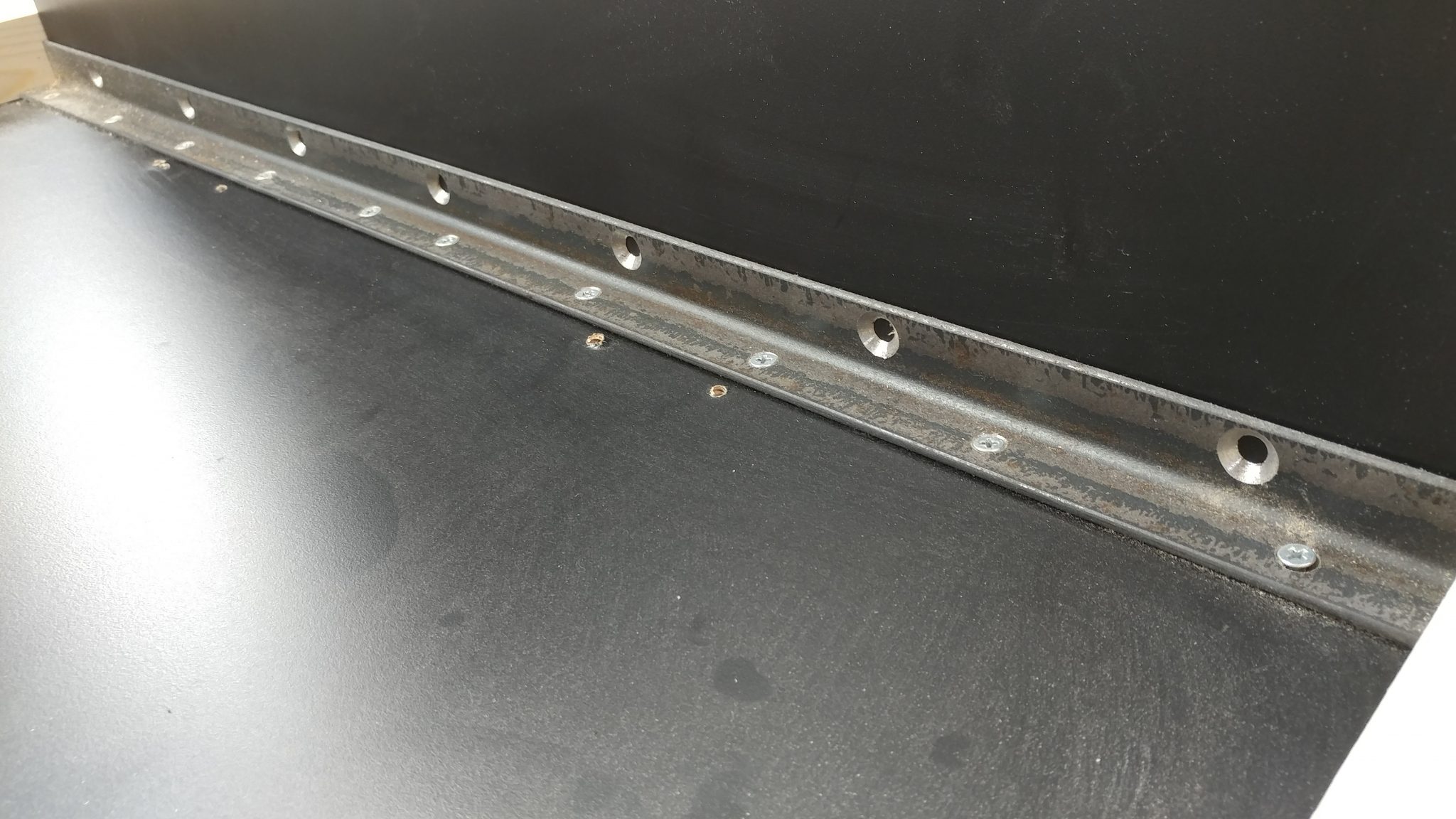
I then pulled the enclosure out so I could drill these holes.
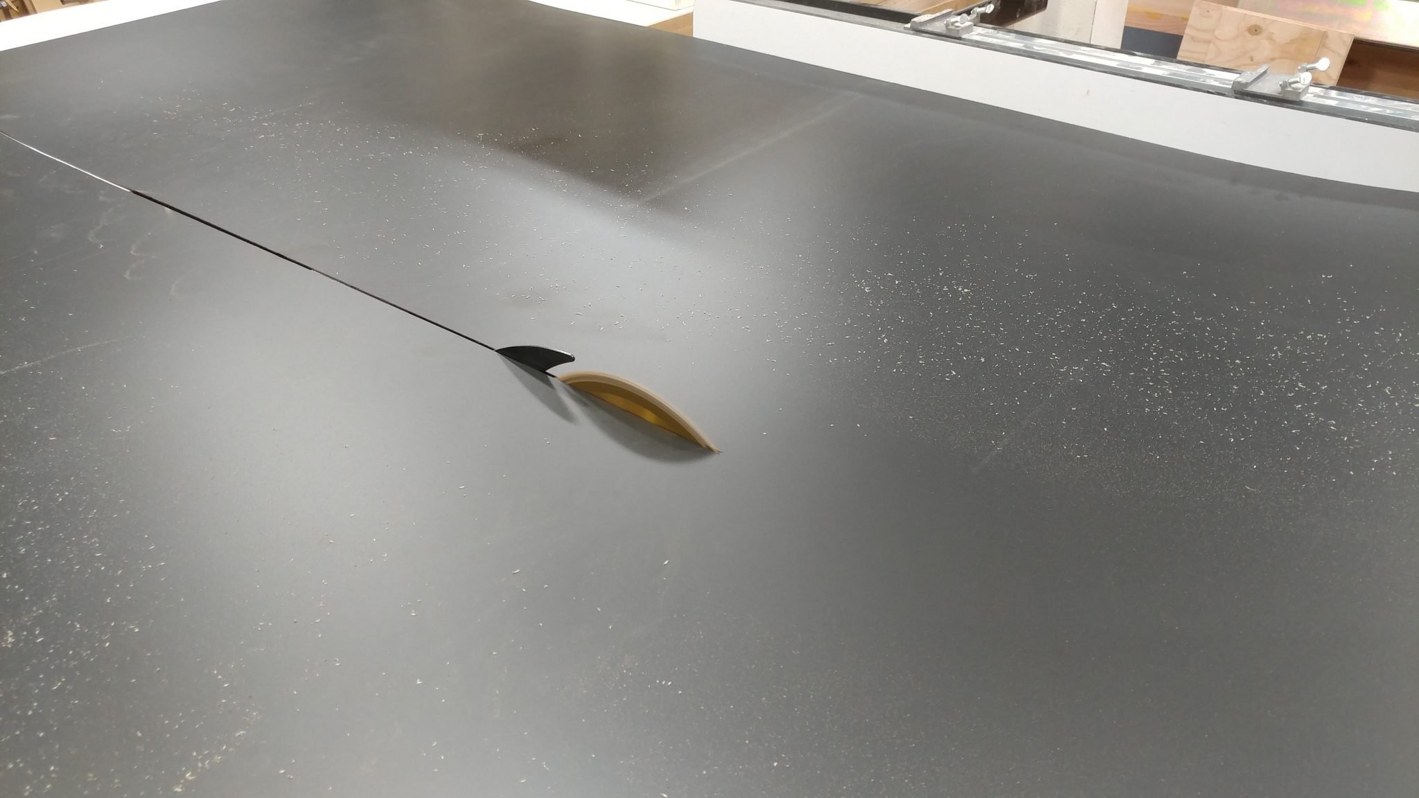
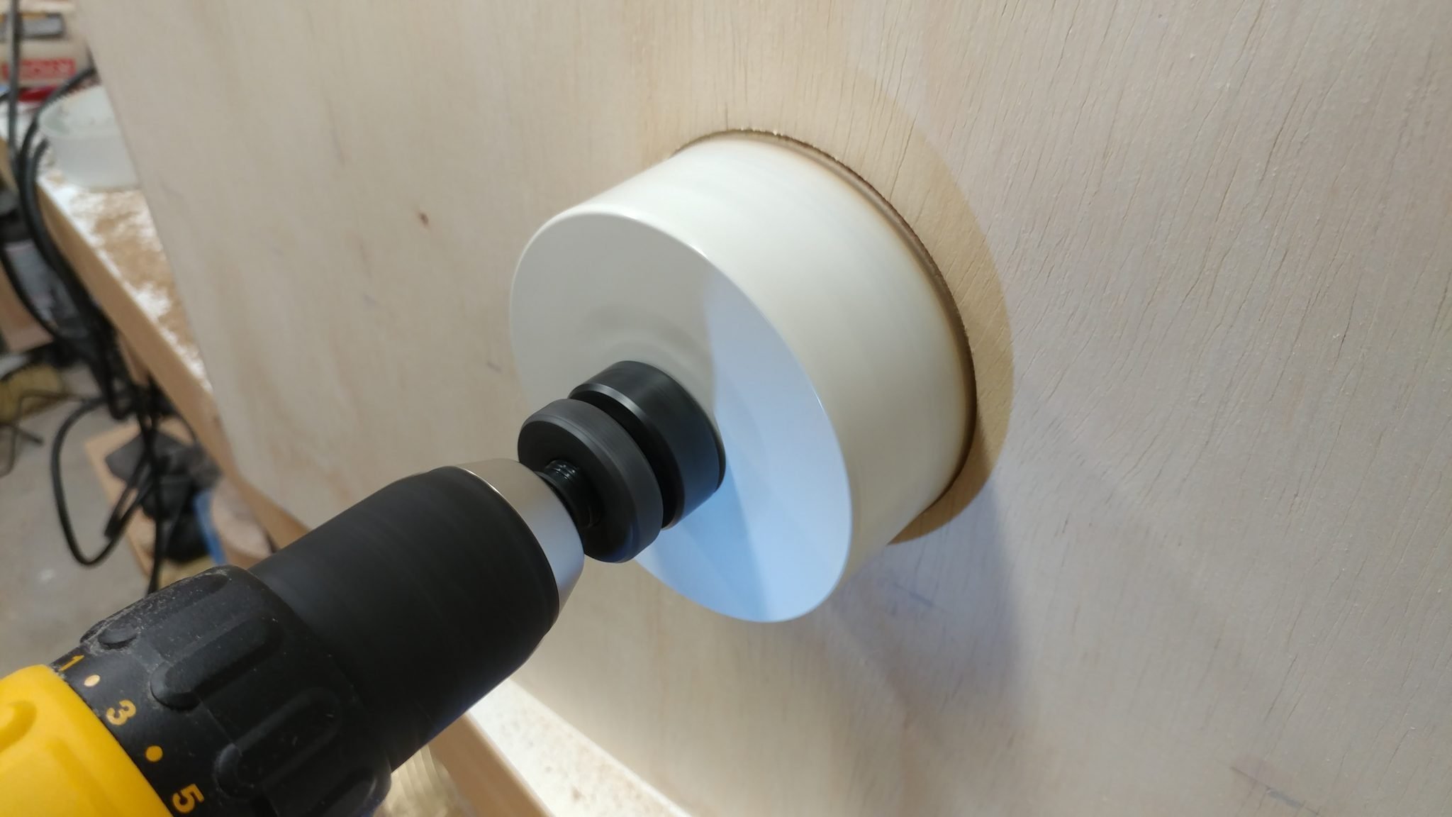
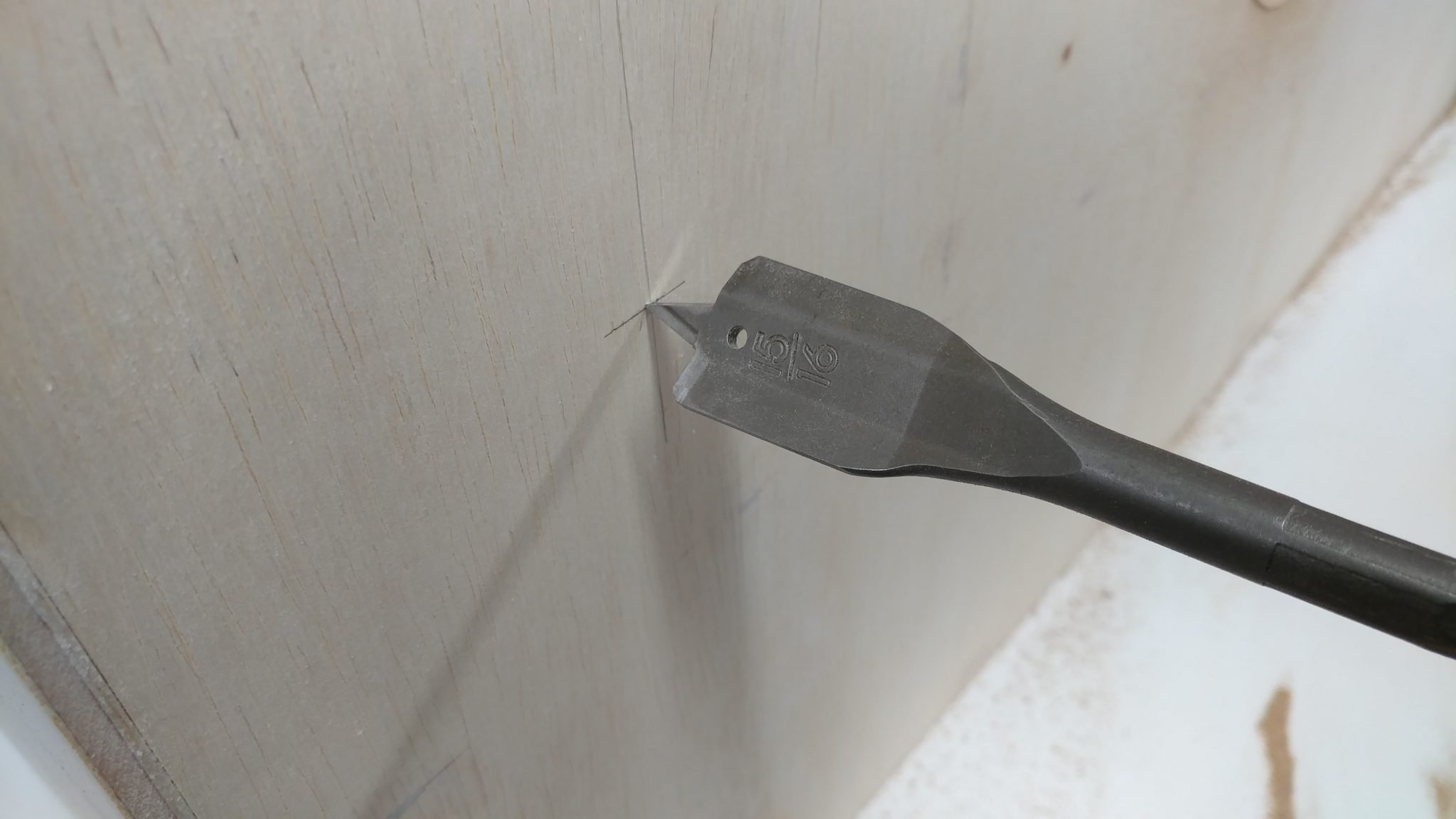
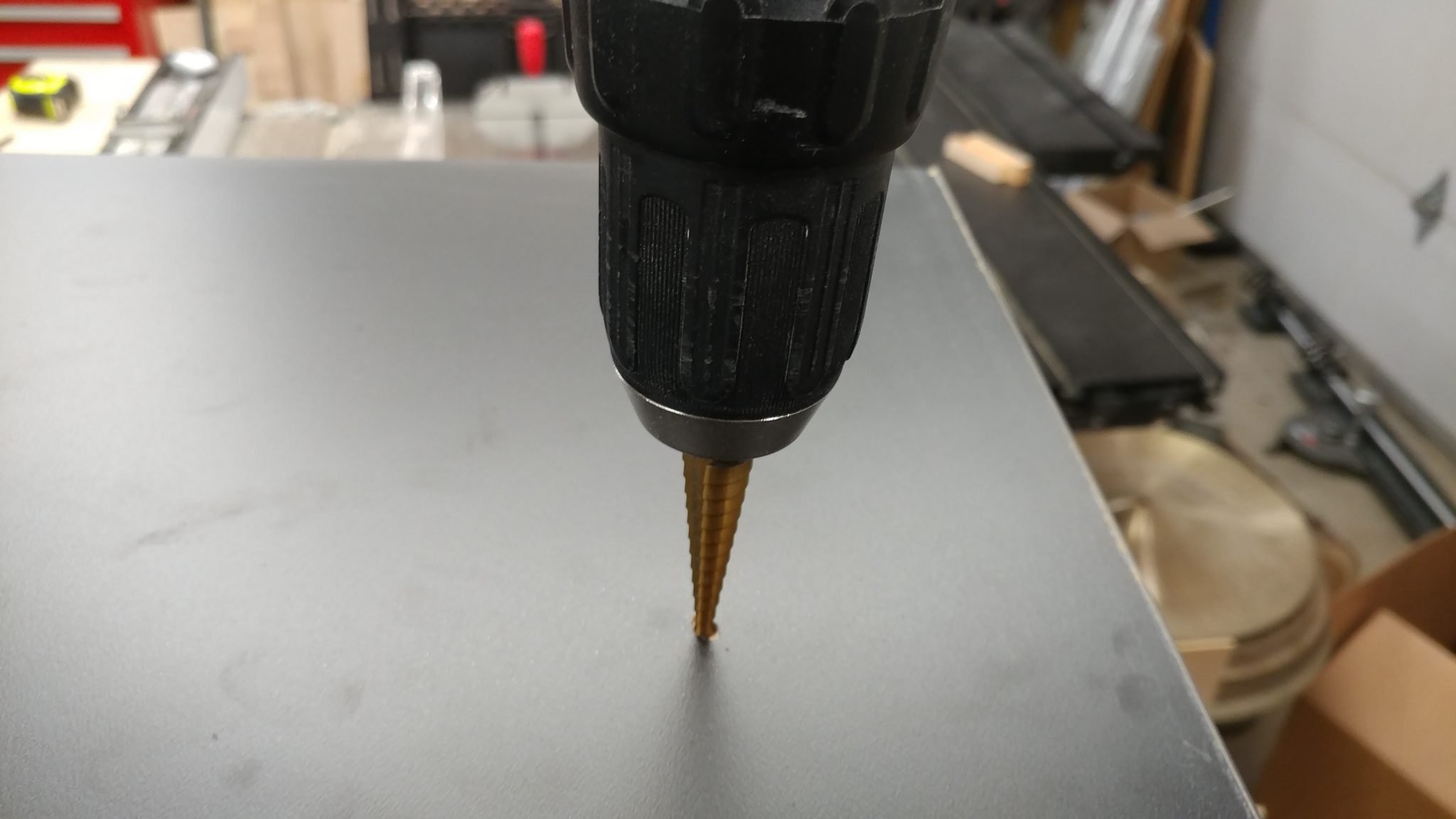
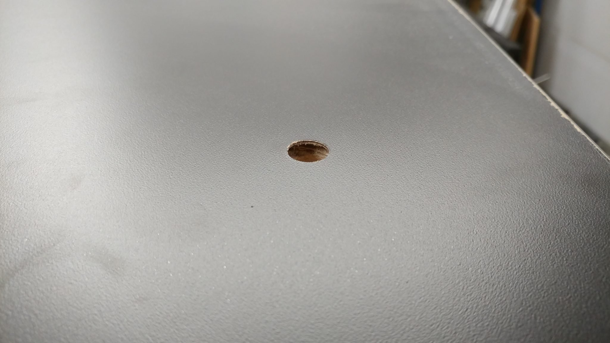
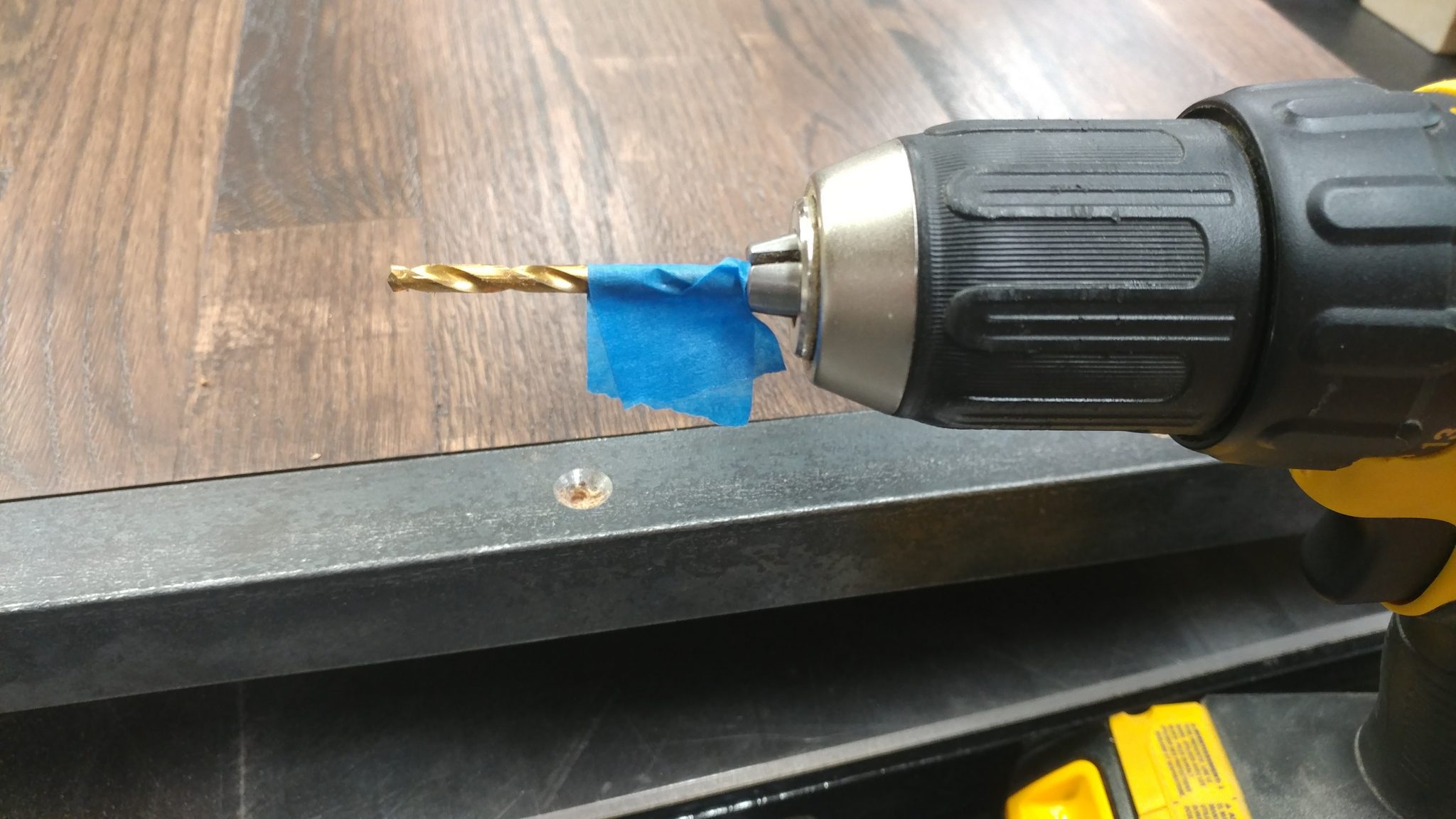
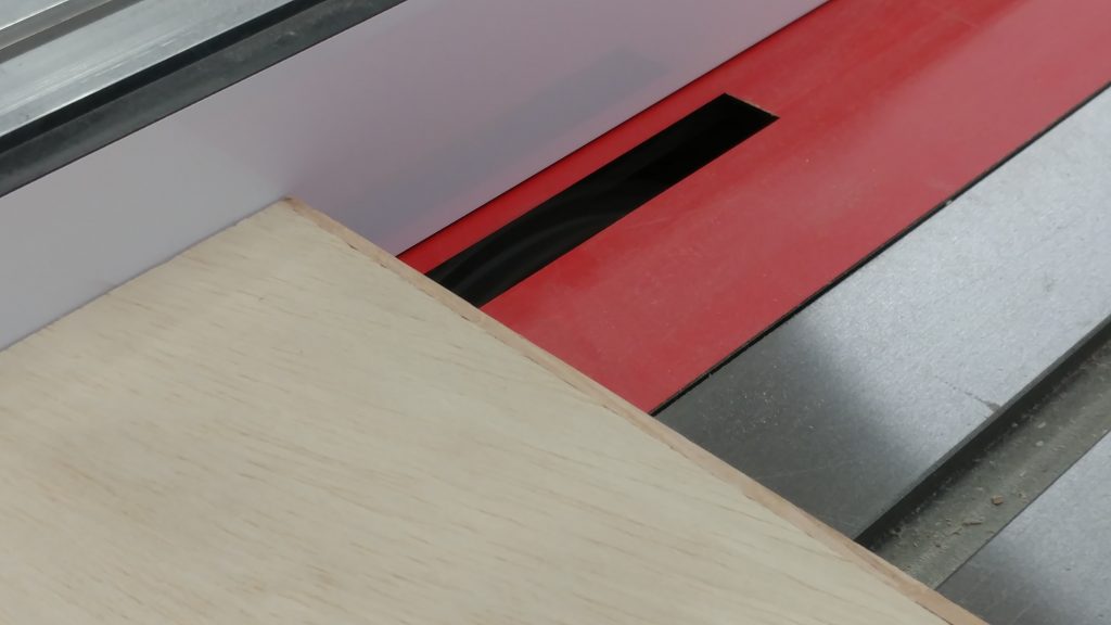
To keep the bit from wandering on the slippery Formica, I drilled a small pilot hole at the center of the mark.
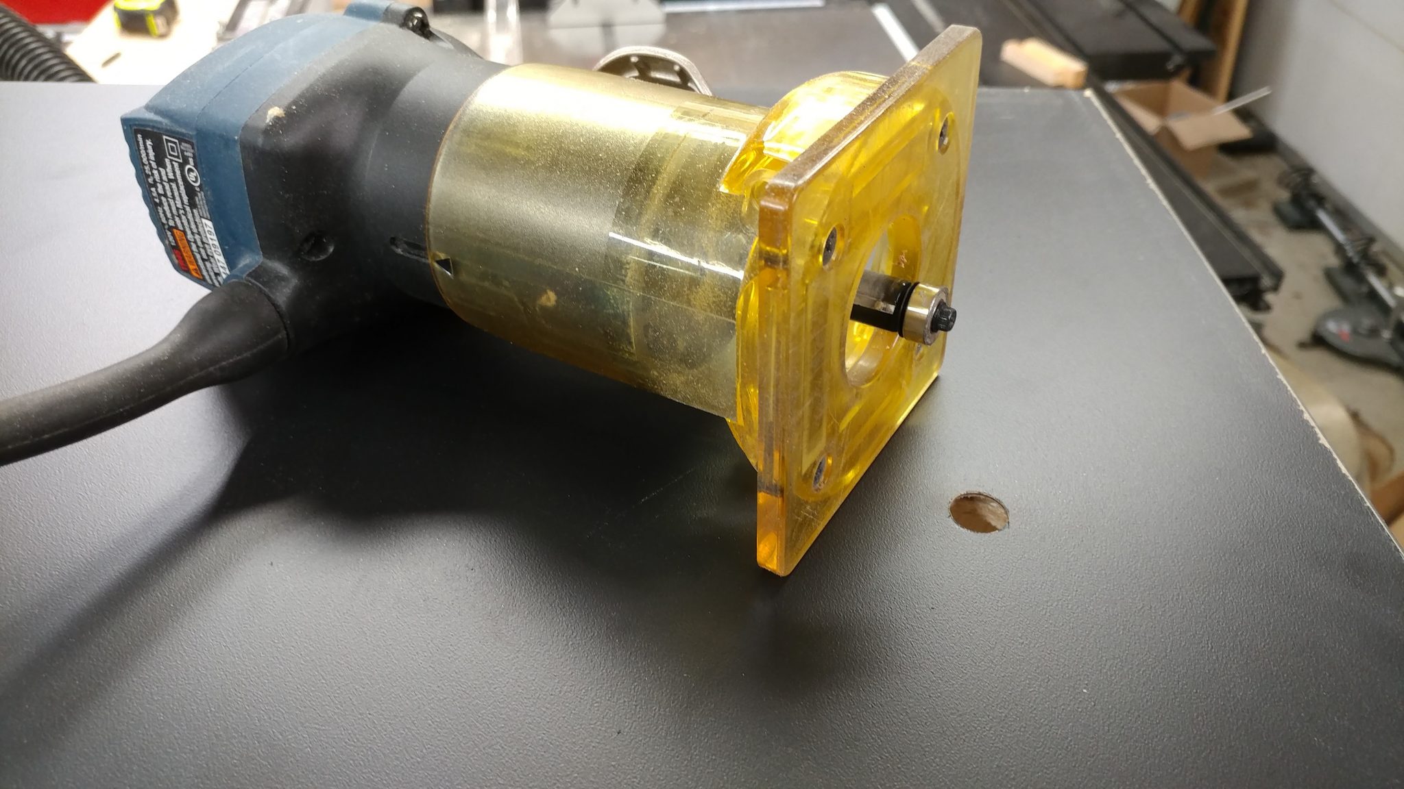
I then drilled the holes.
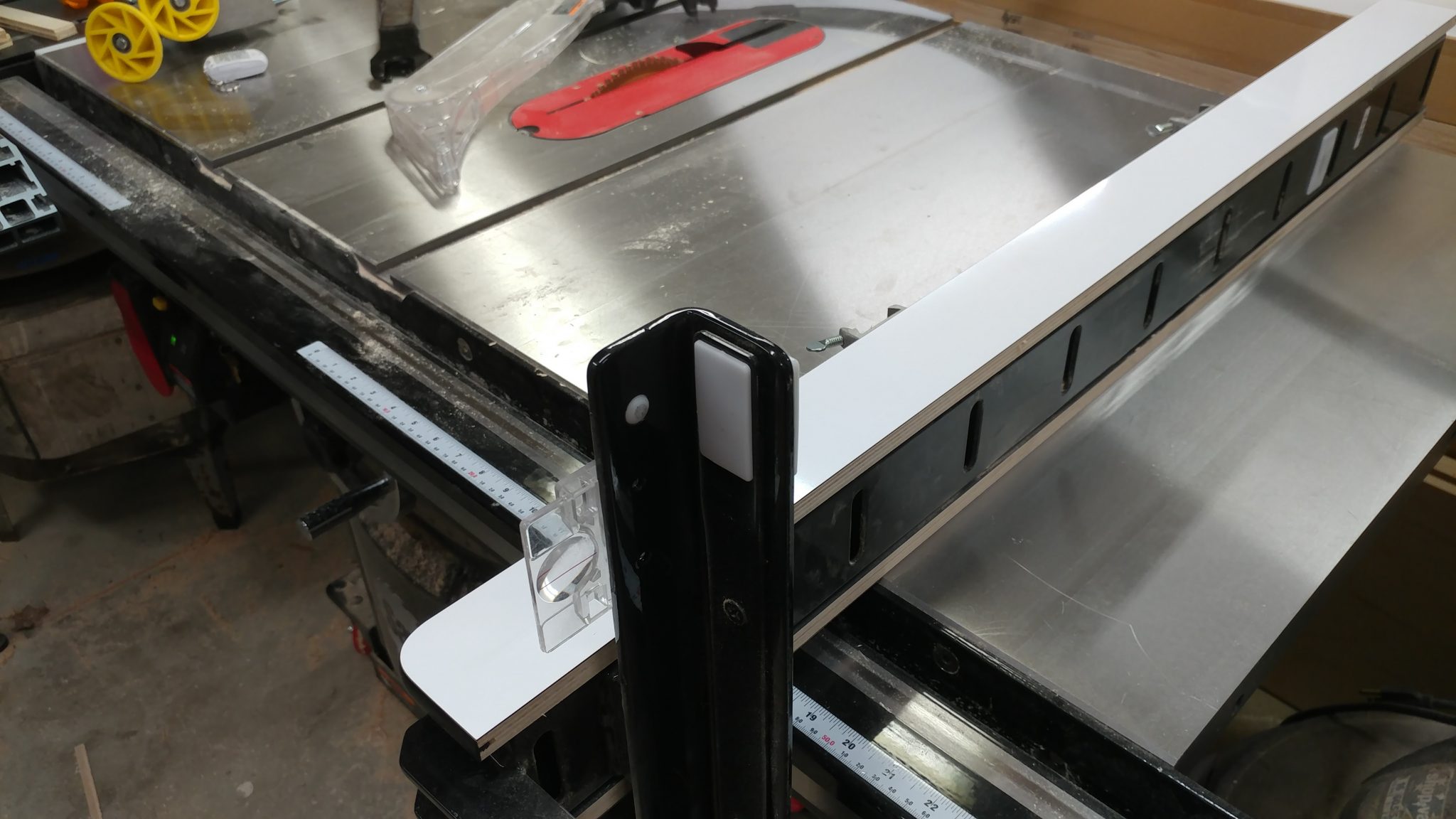
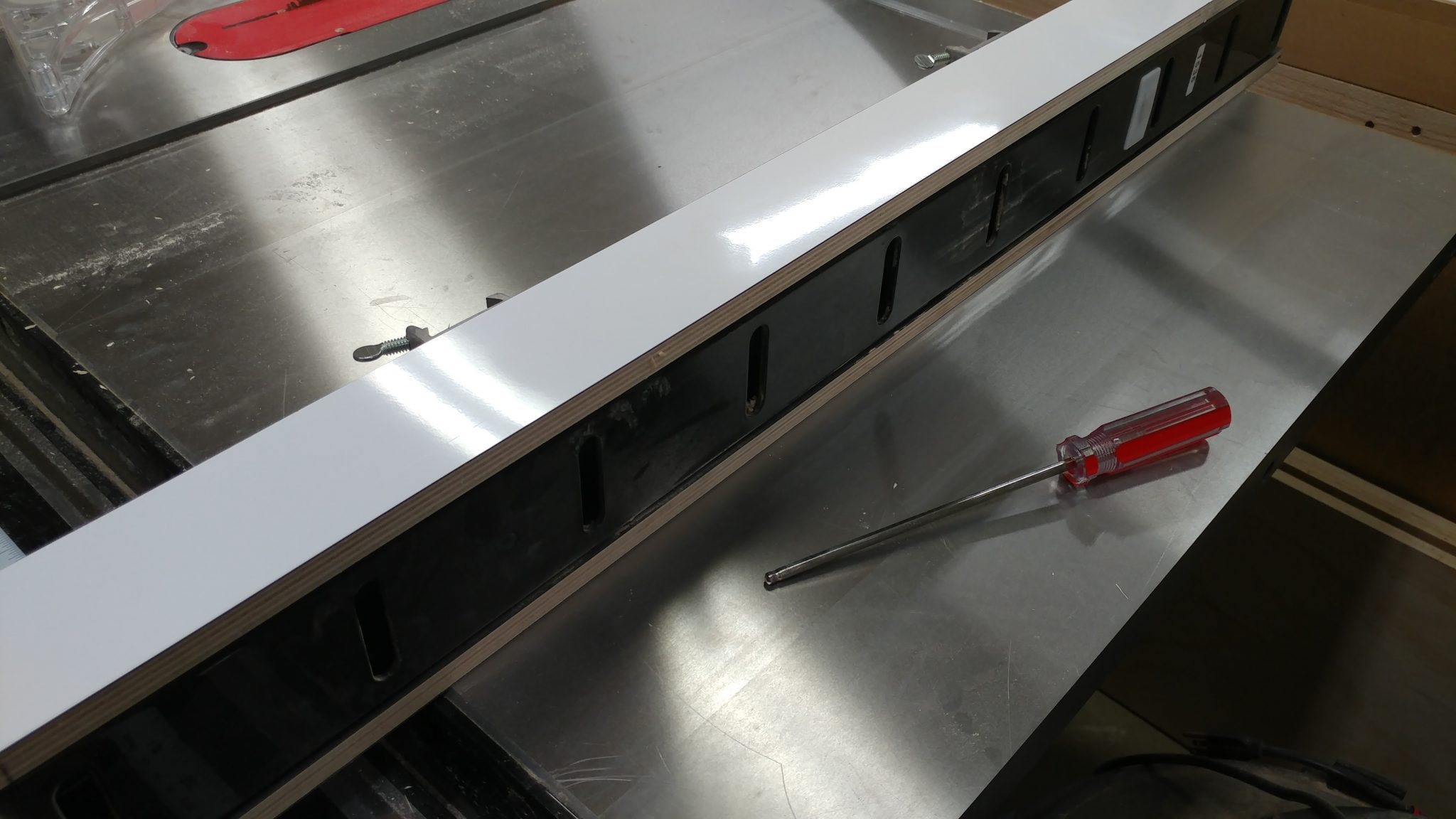
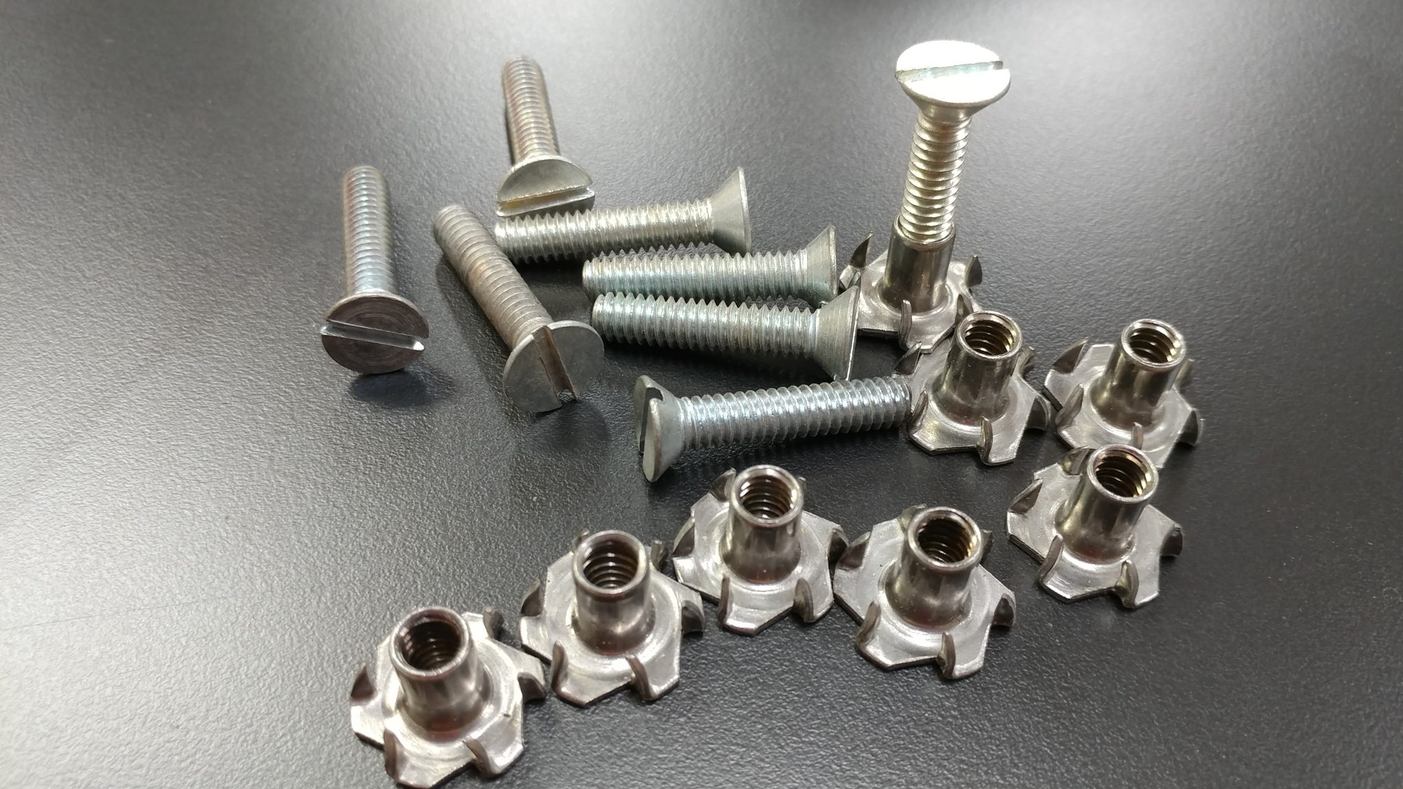
I also wanted to insert some tee-nuts into the holes to help strengthen it a bit. I started by taking the table out and setting it on its side so I could access these holes.
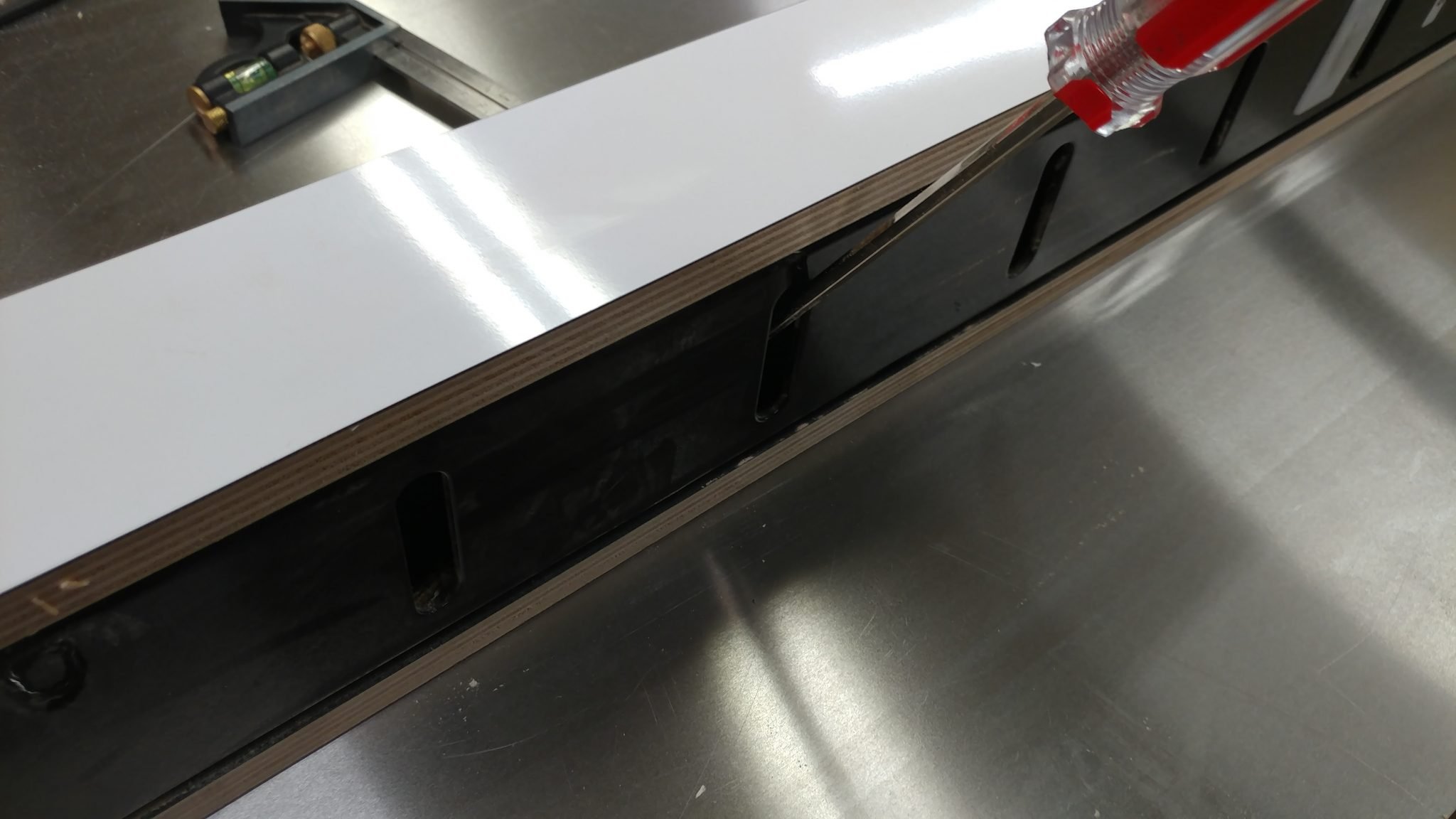
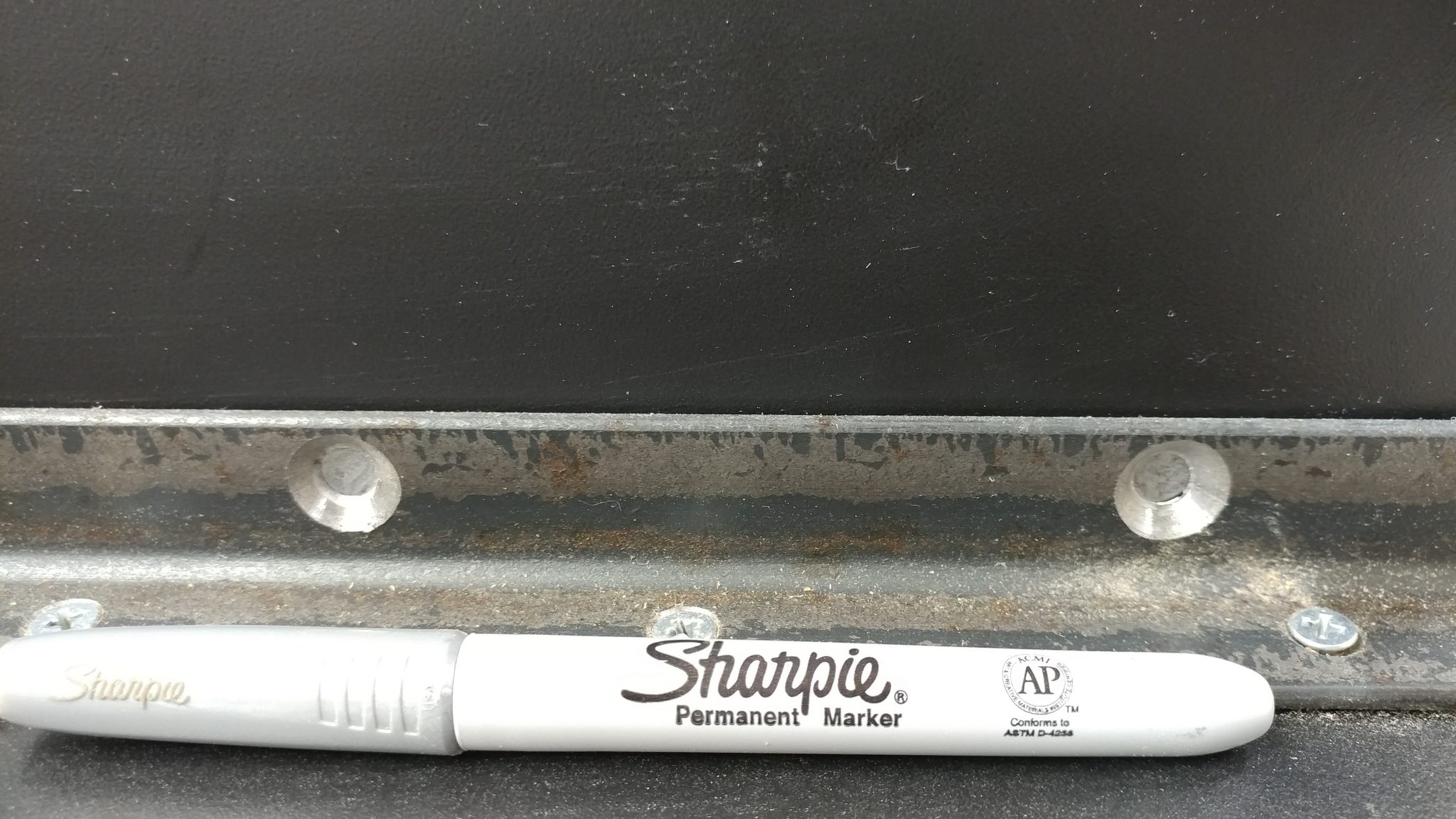
The tee-nuts fit into the holes perfectly.
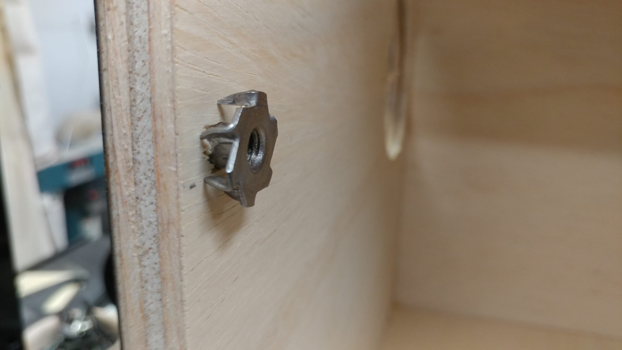
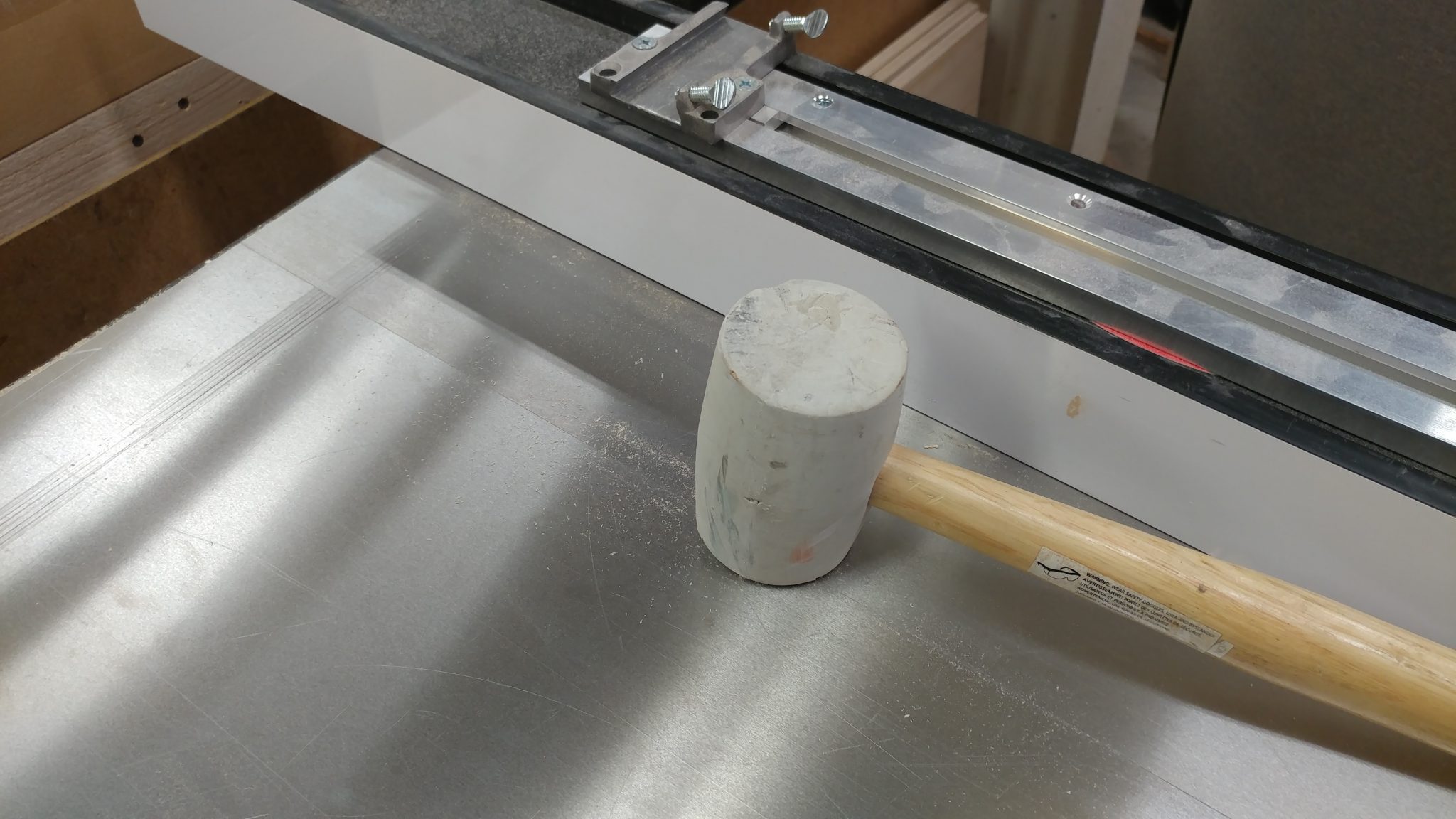
These were easy to hammer into the holes as long as I supported the board on the opposite side.
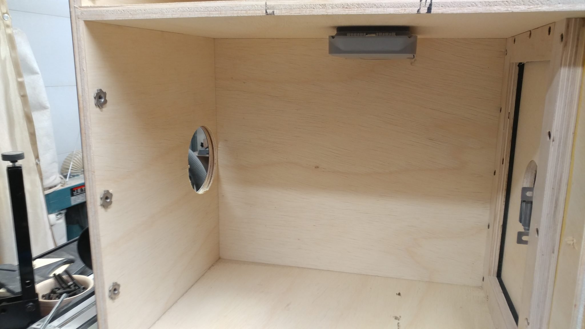
I put the enclosure back in place.
I installed the screws. They hold it nicely. Almost too nicely. I was actually surprised that this worked as well as it did.

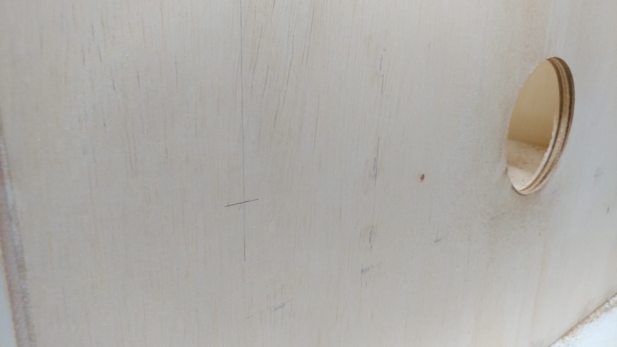
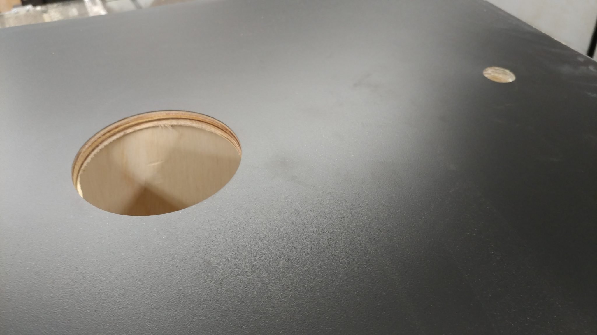
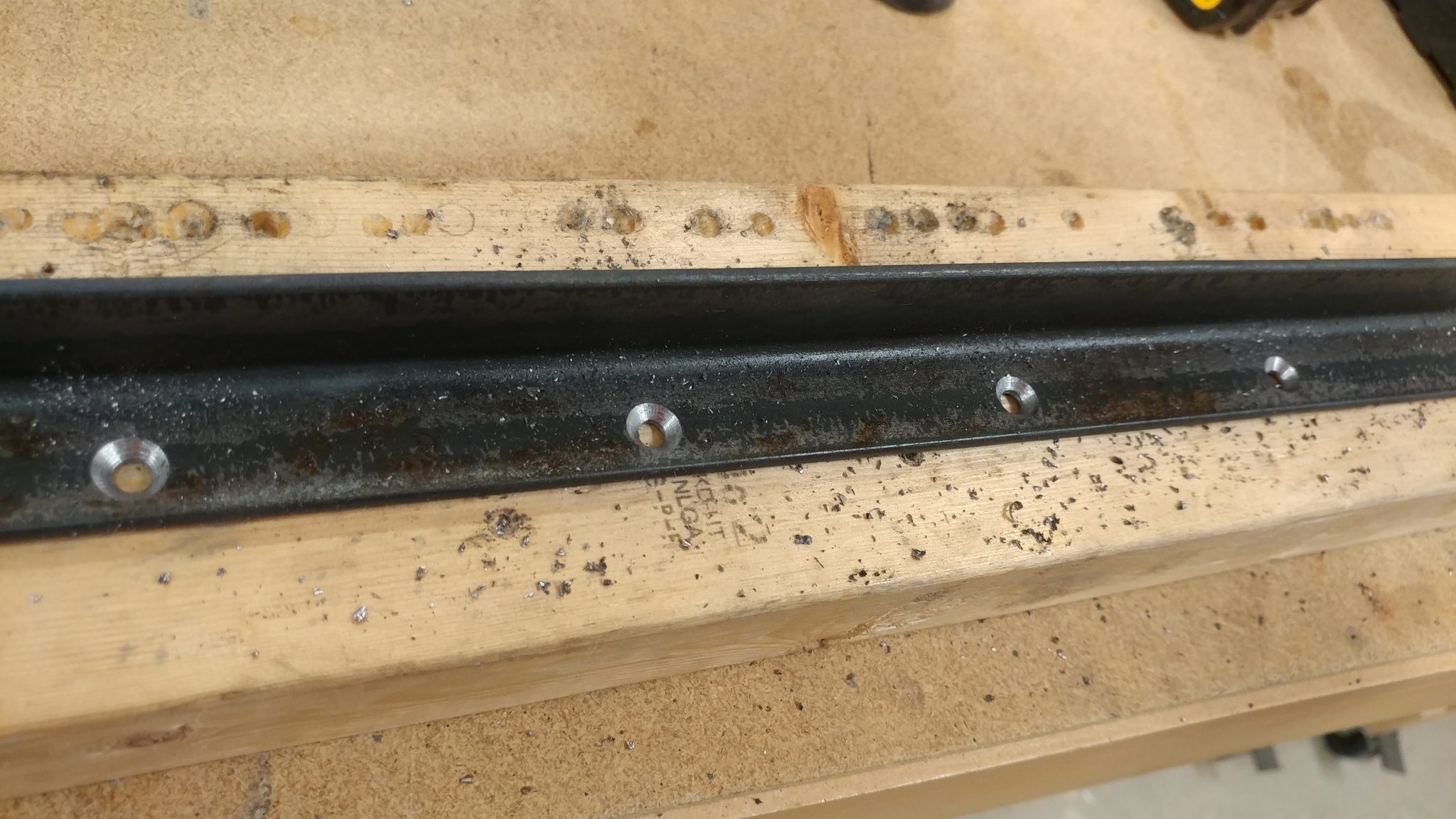
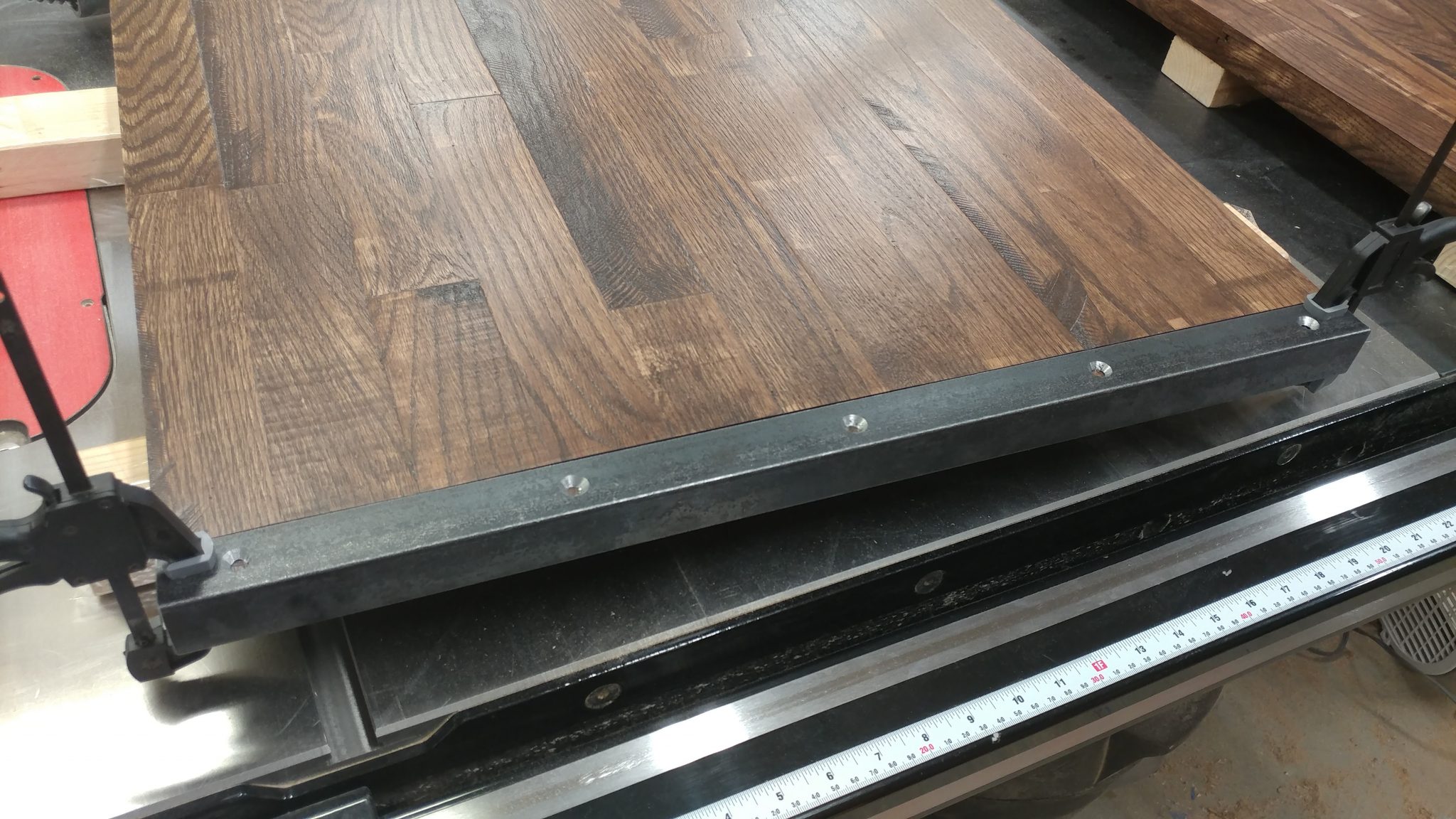
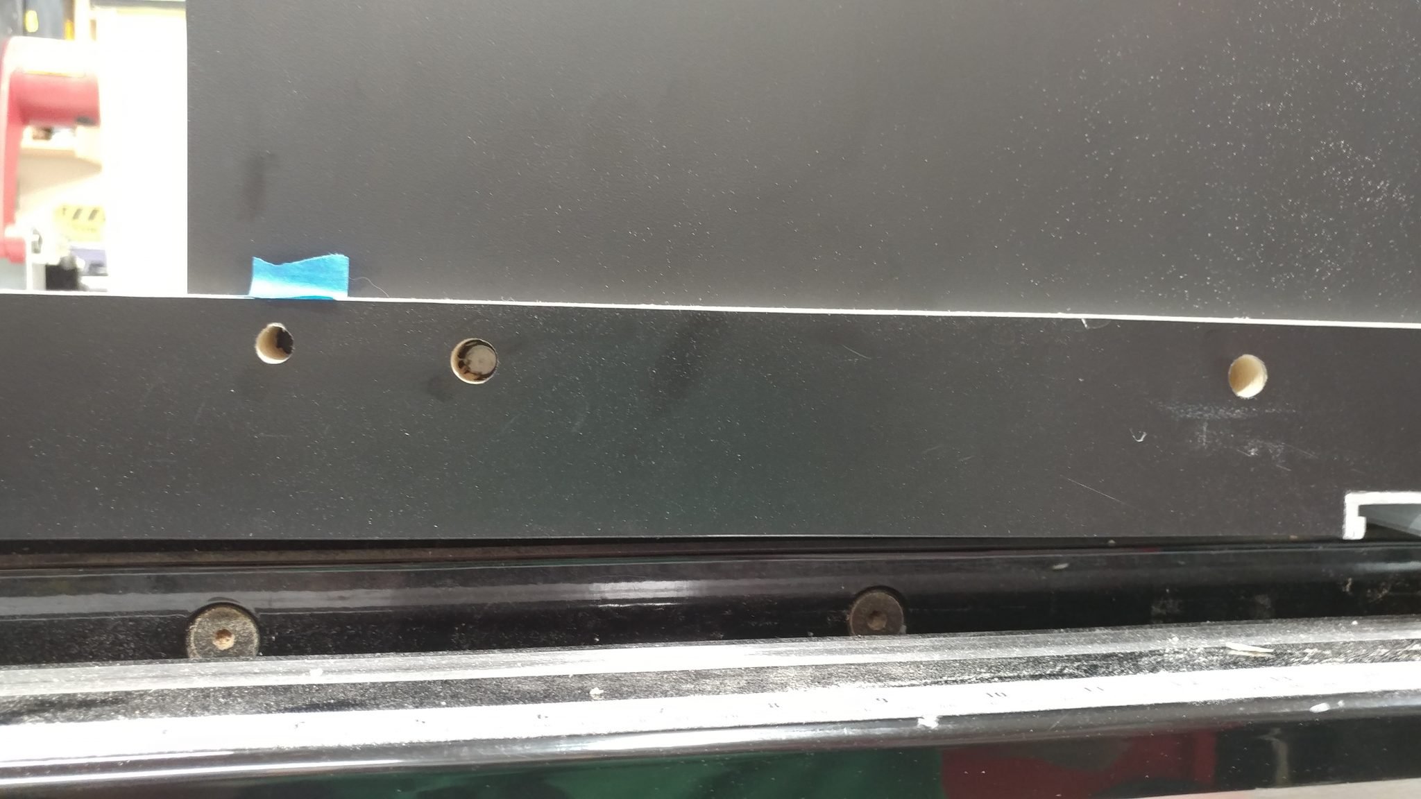
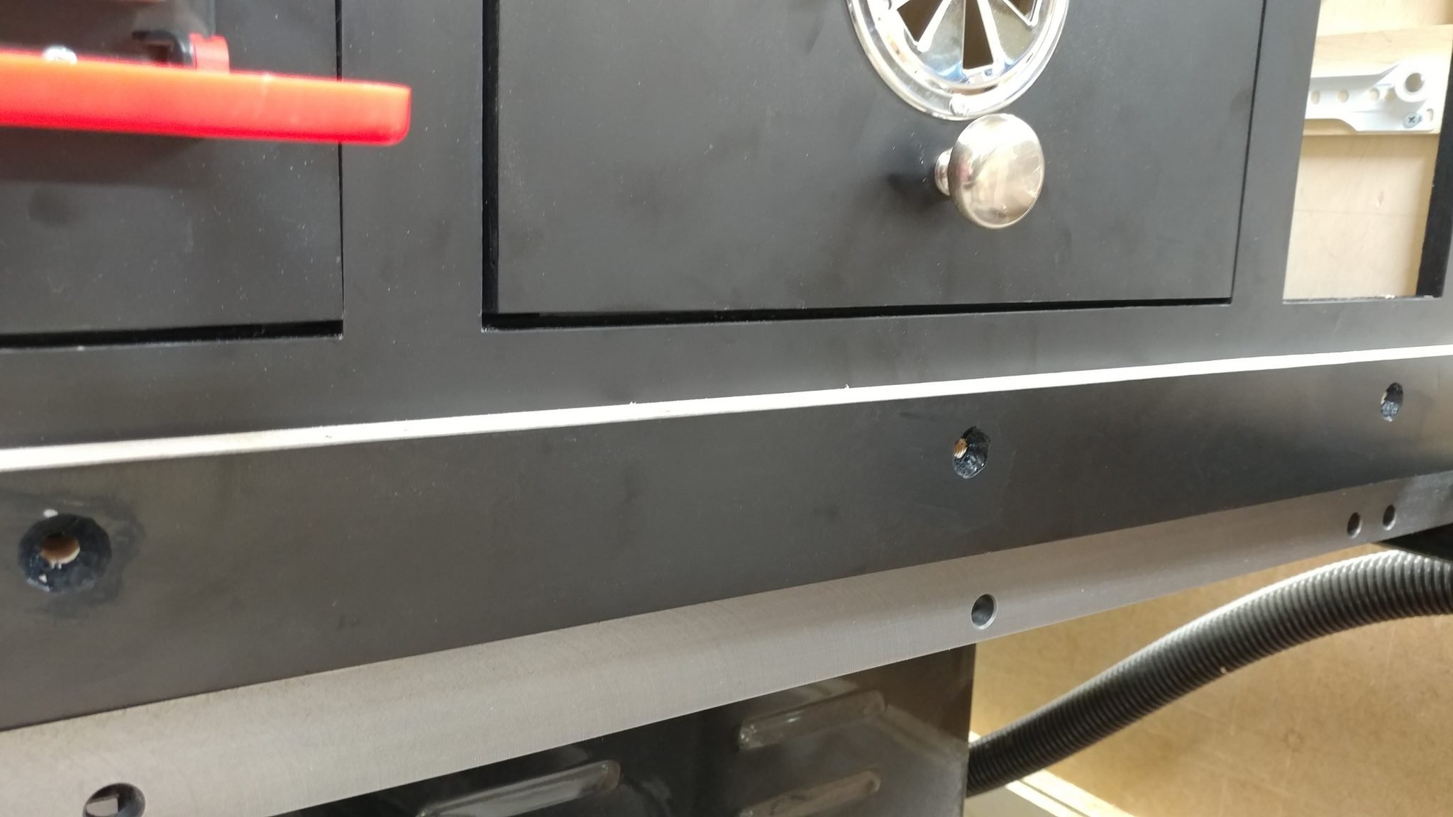
I marked where I would drill three holes in the front where I would secure the enclosure to the table. I drilled these holes.
Since I’m using the countersunk screws that would normally attach the extension table to the rails, I needed them to be countersunk.
I painted the countersunk area black so it would blend in better. Then I installed the screws and secured them with washers and lock nuts.
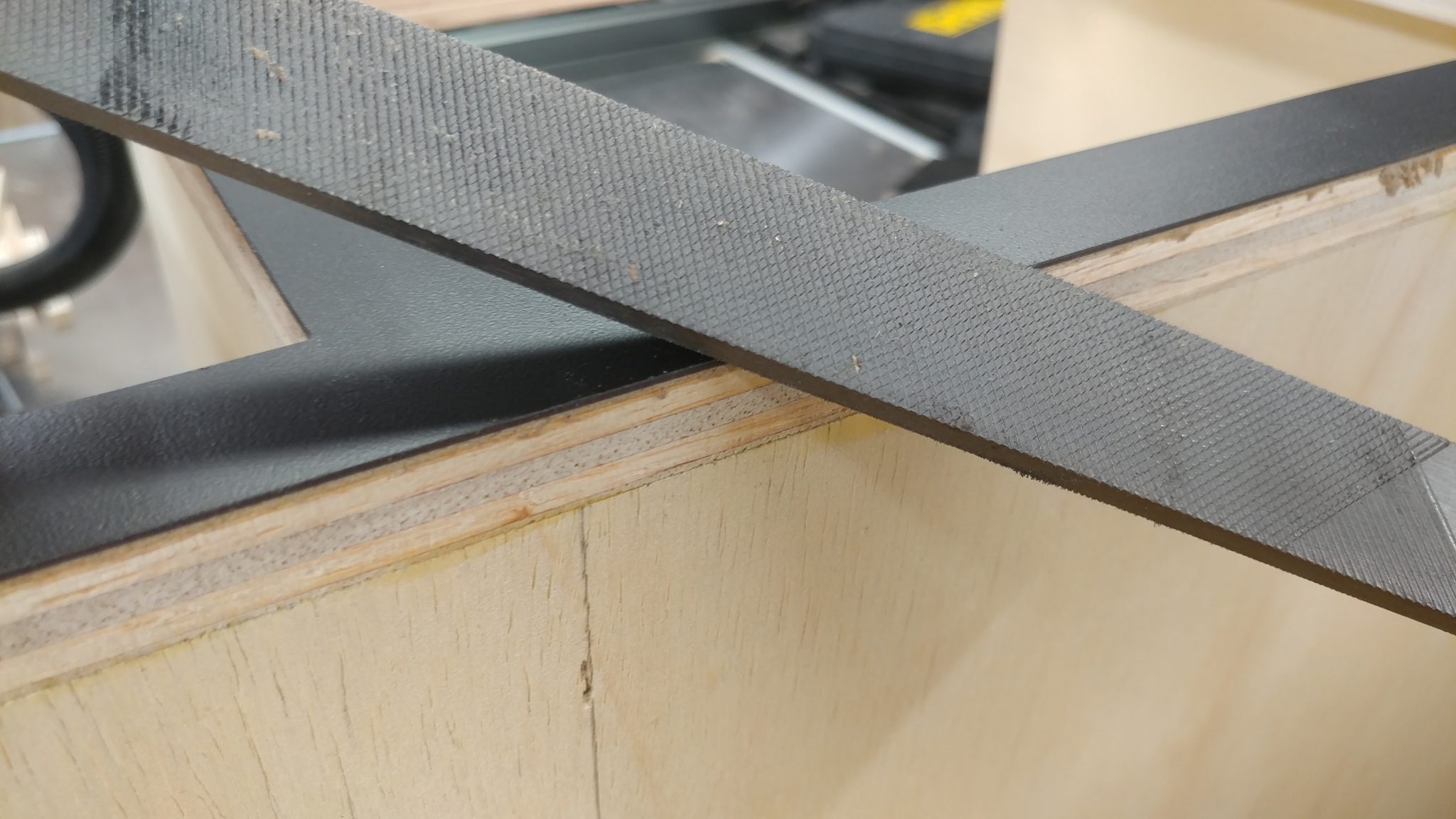
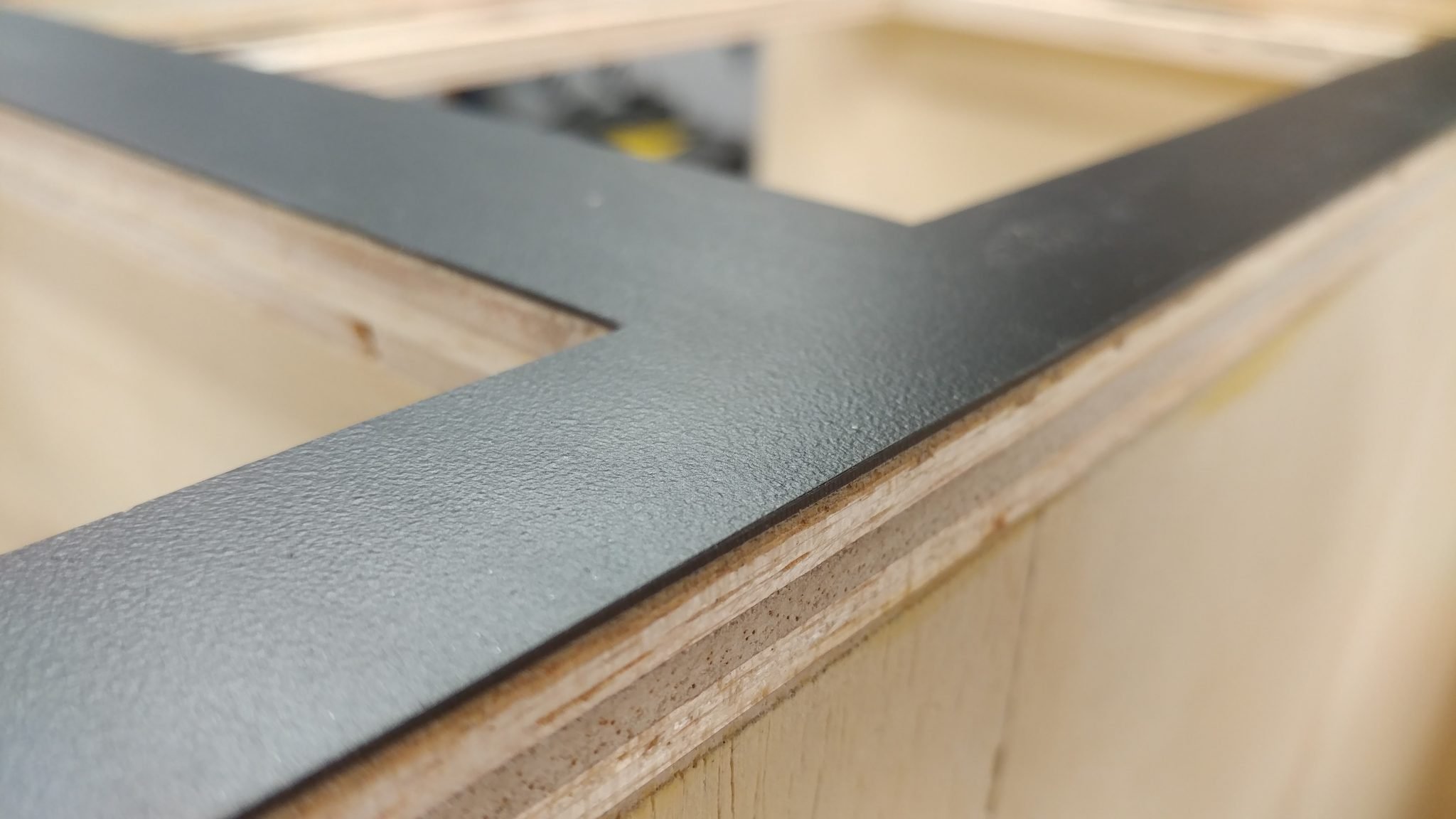
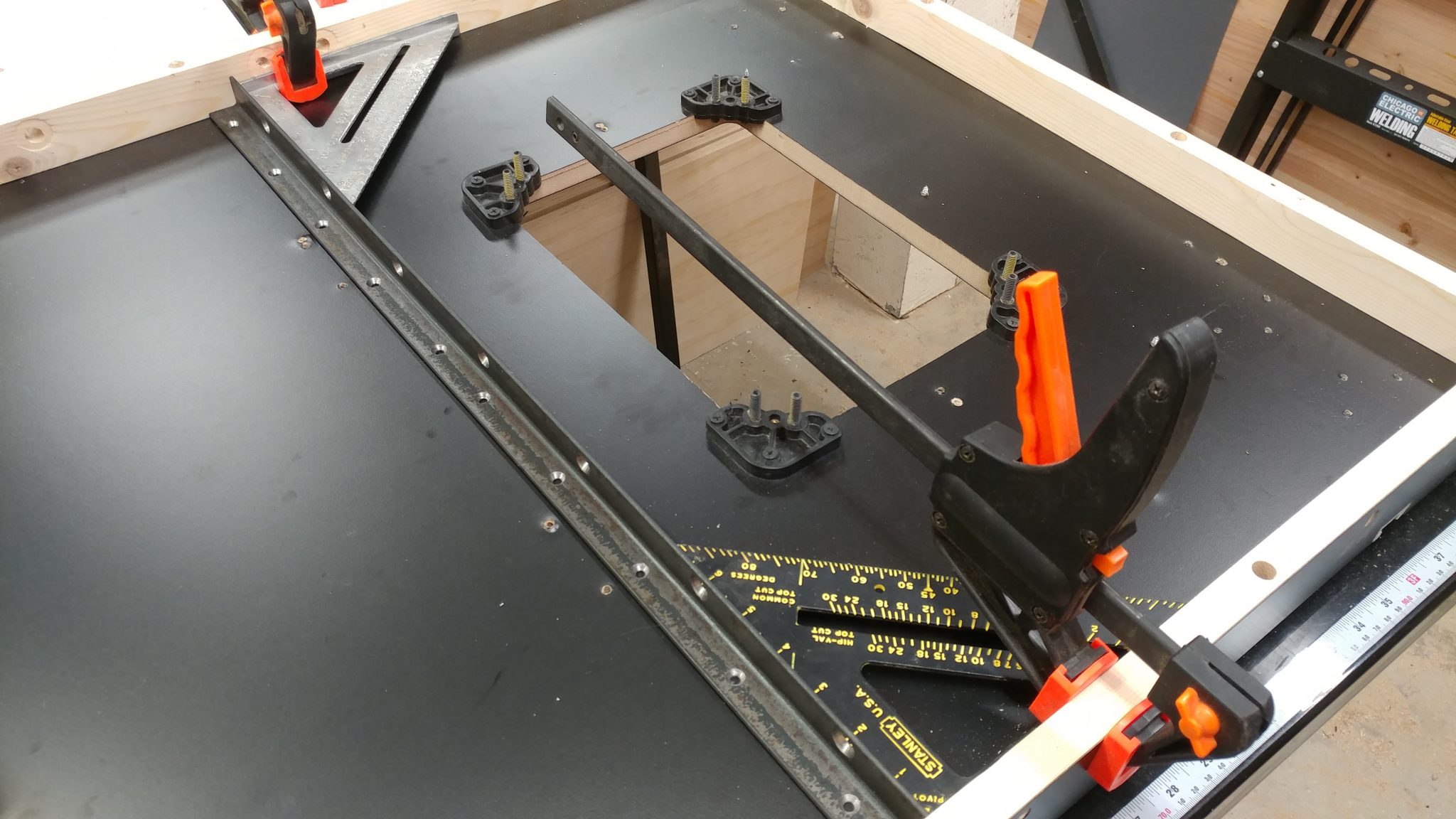
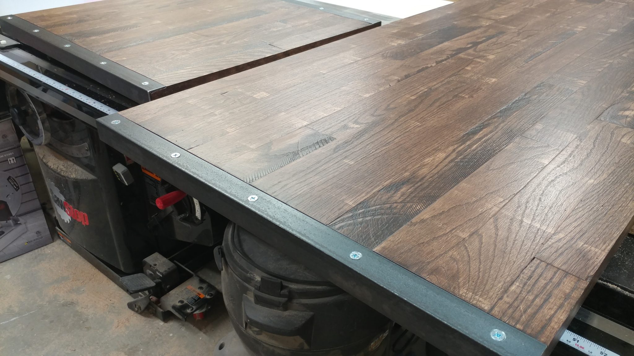
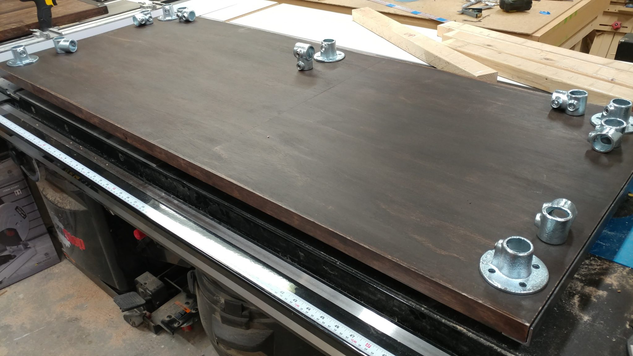
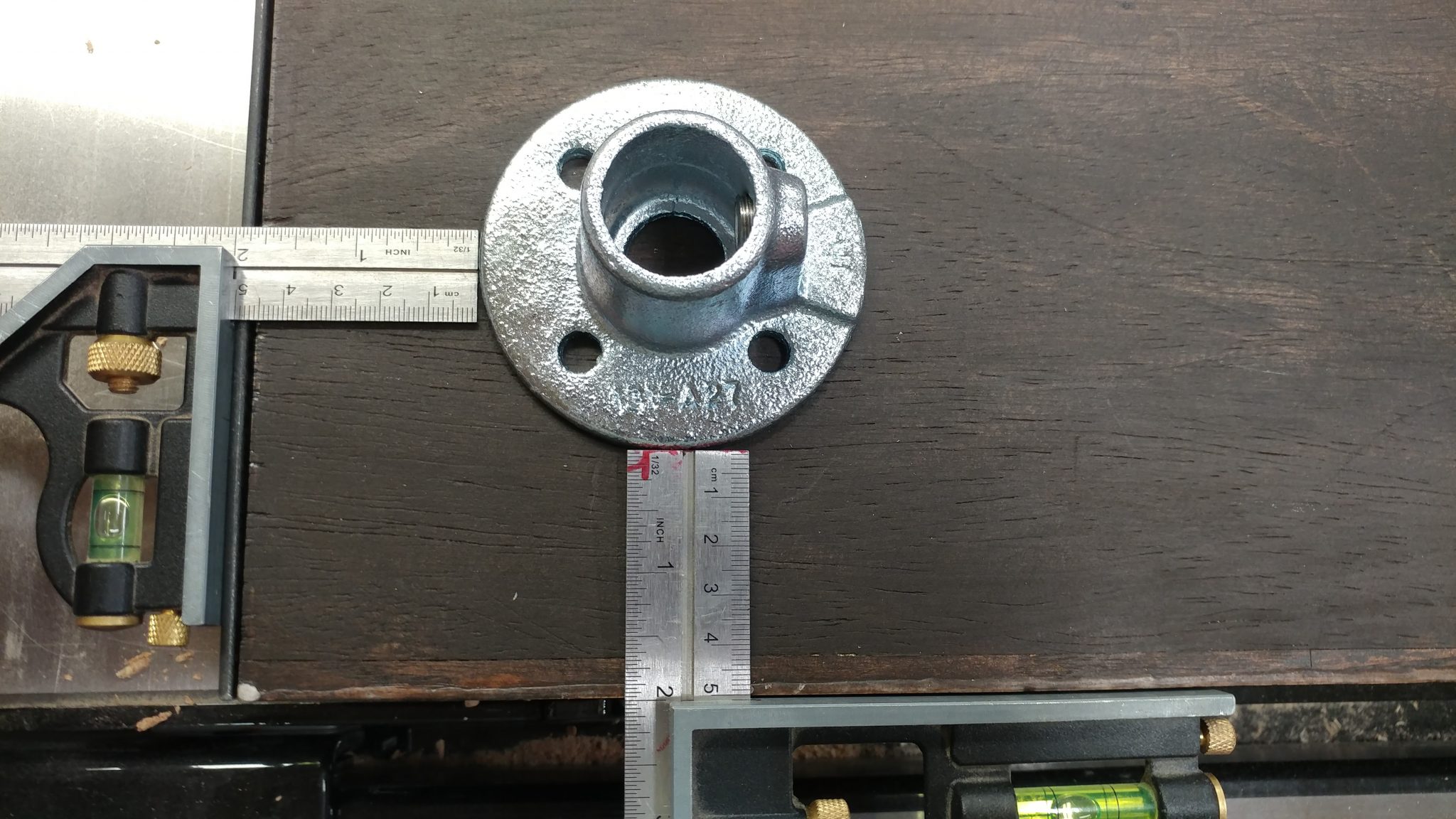
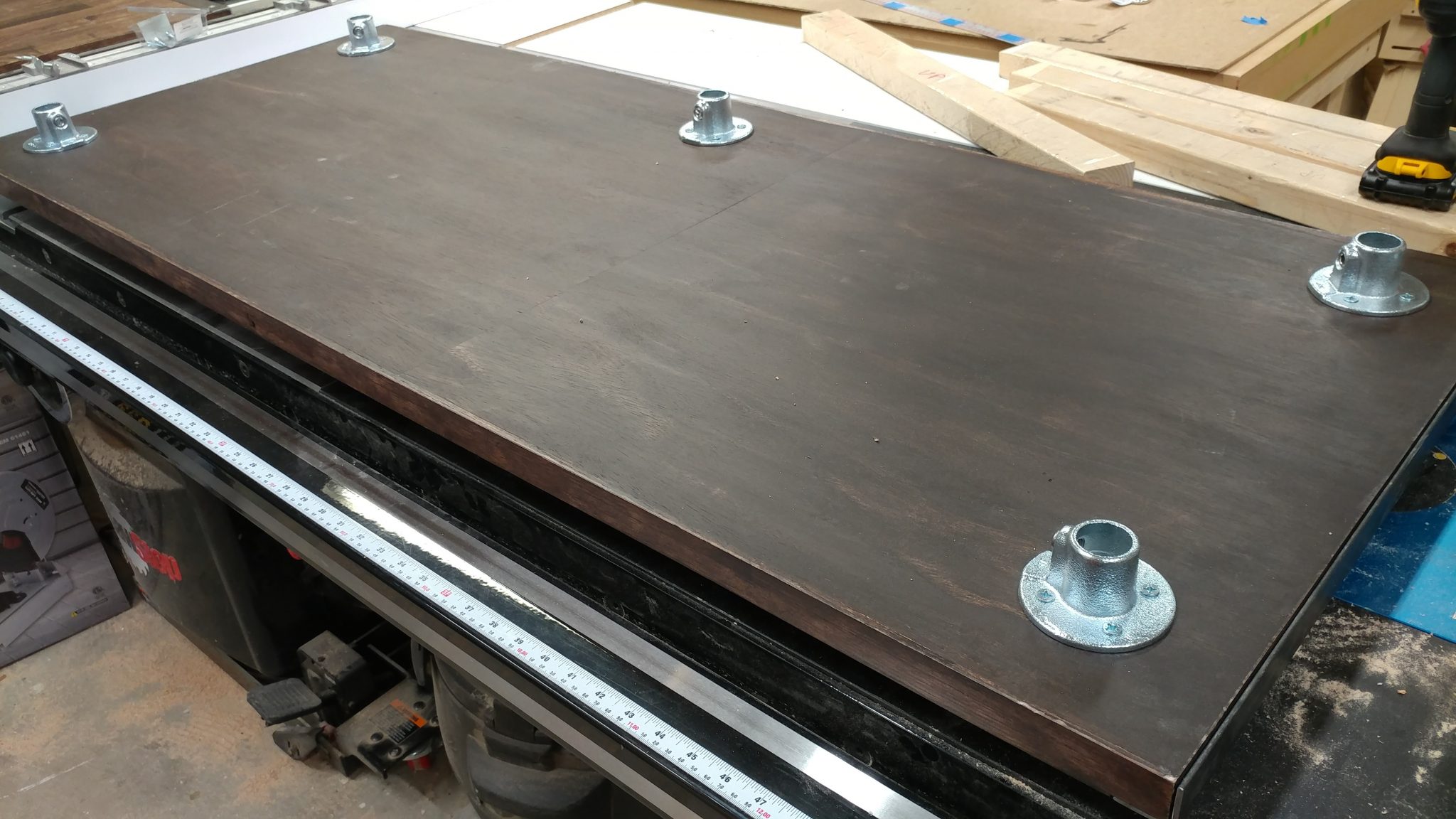
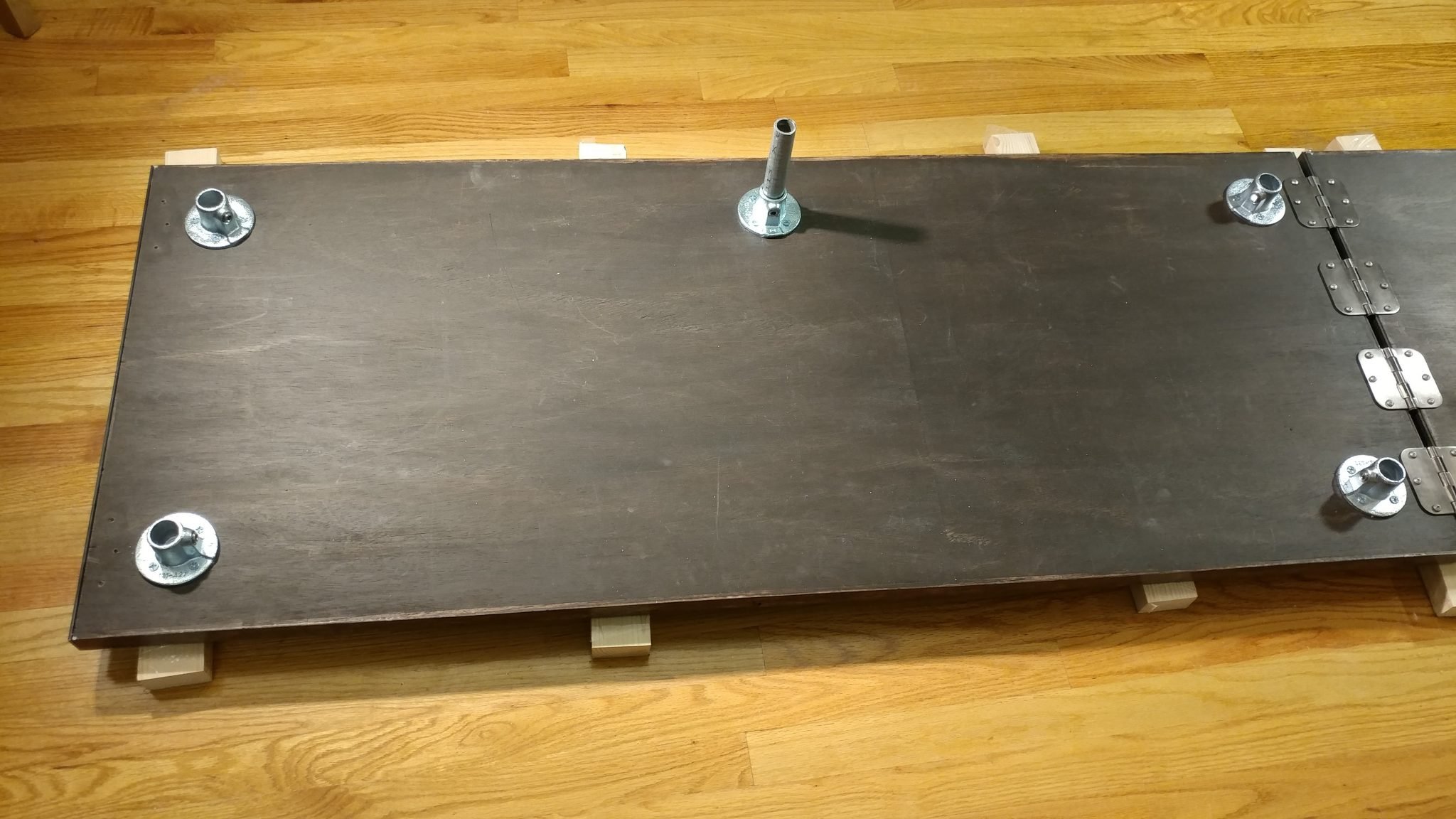
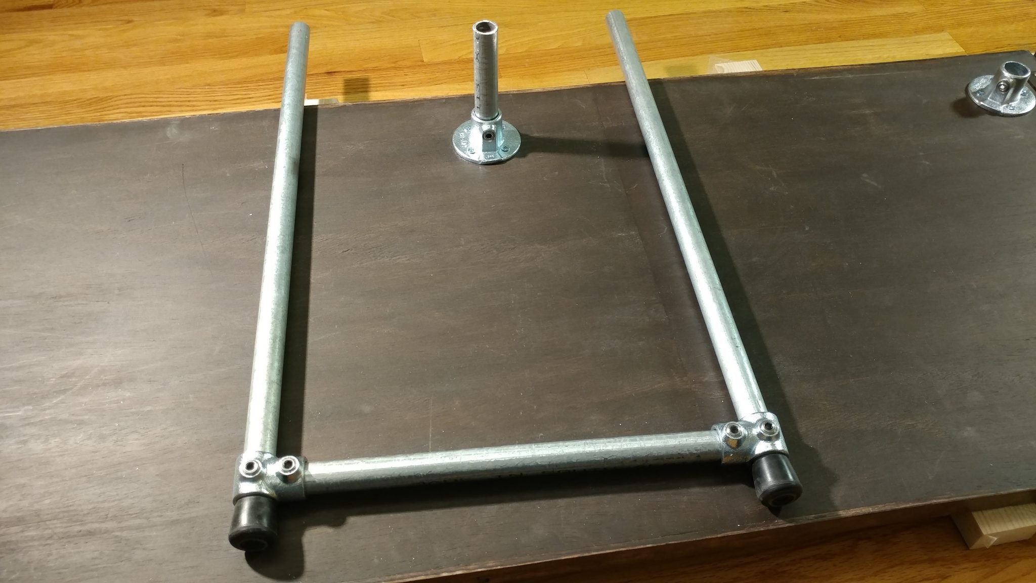
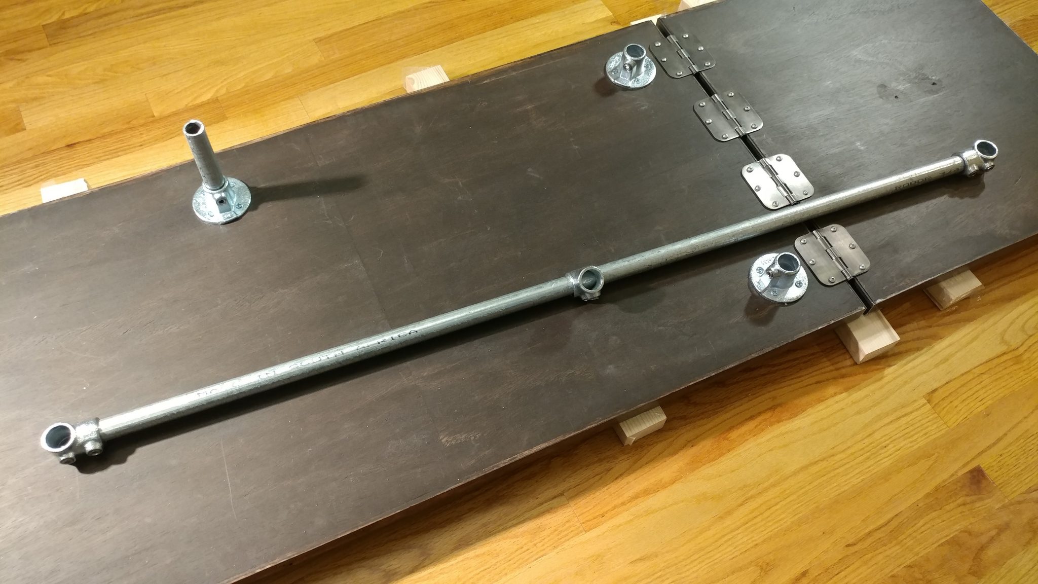
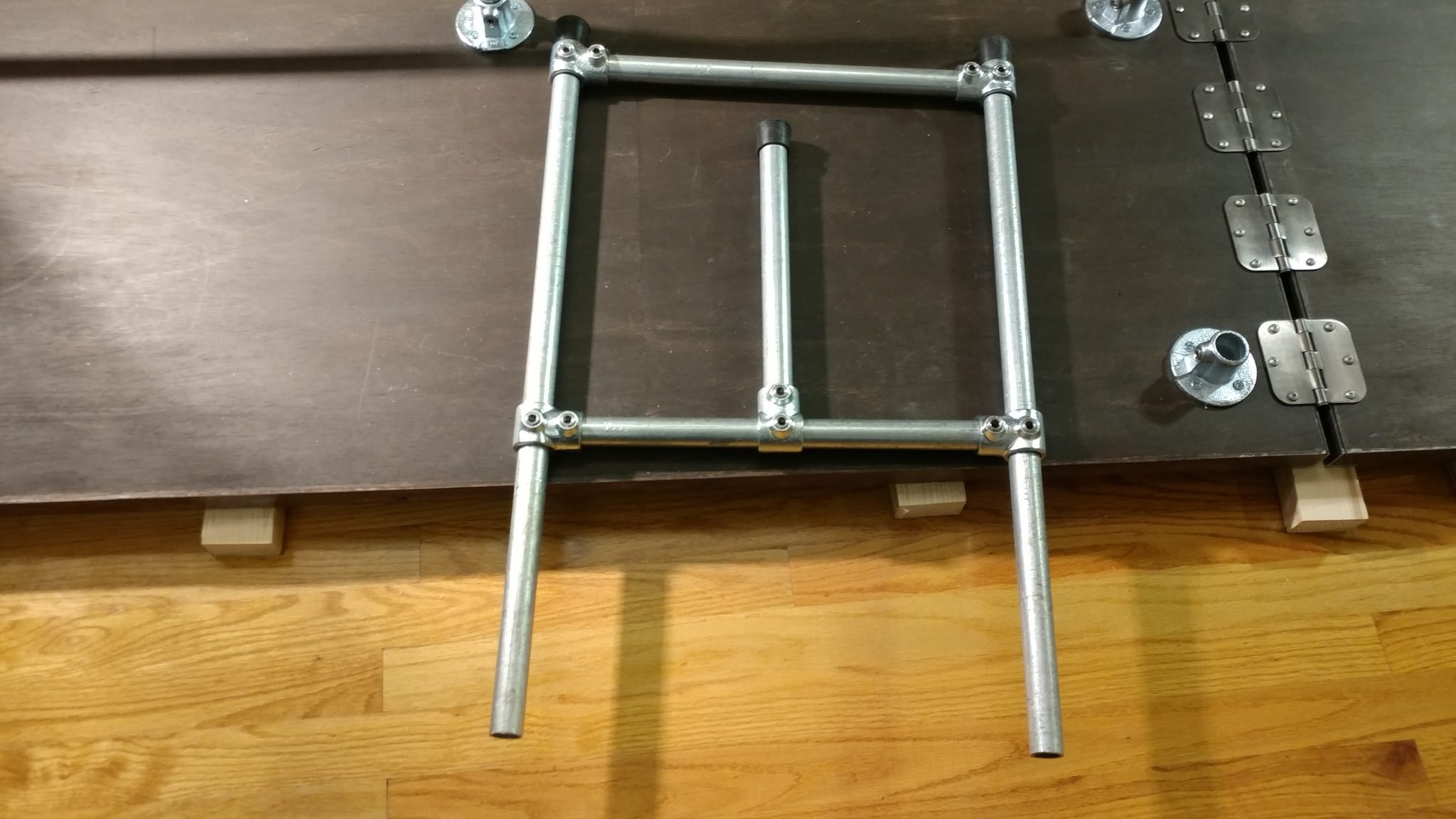
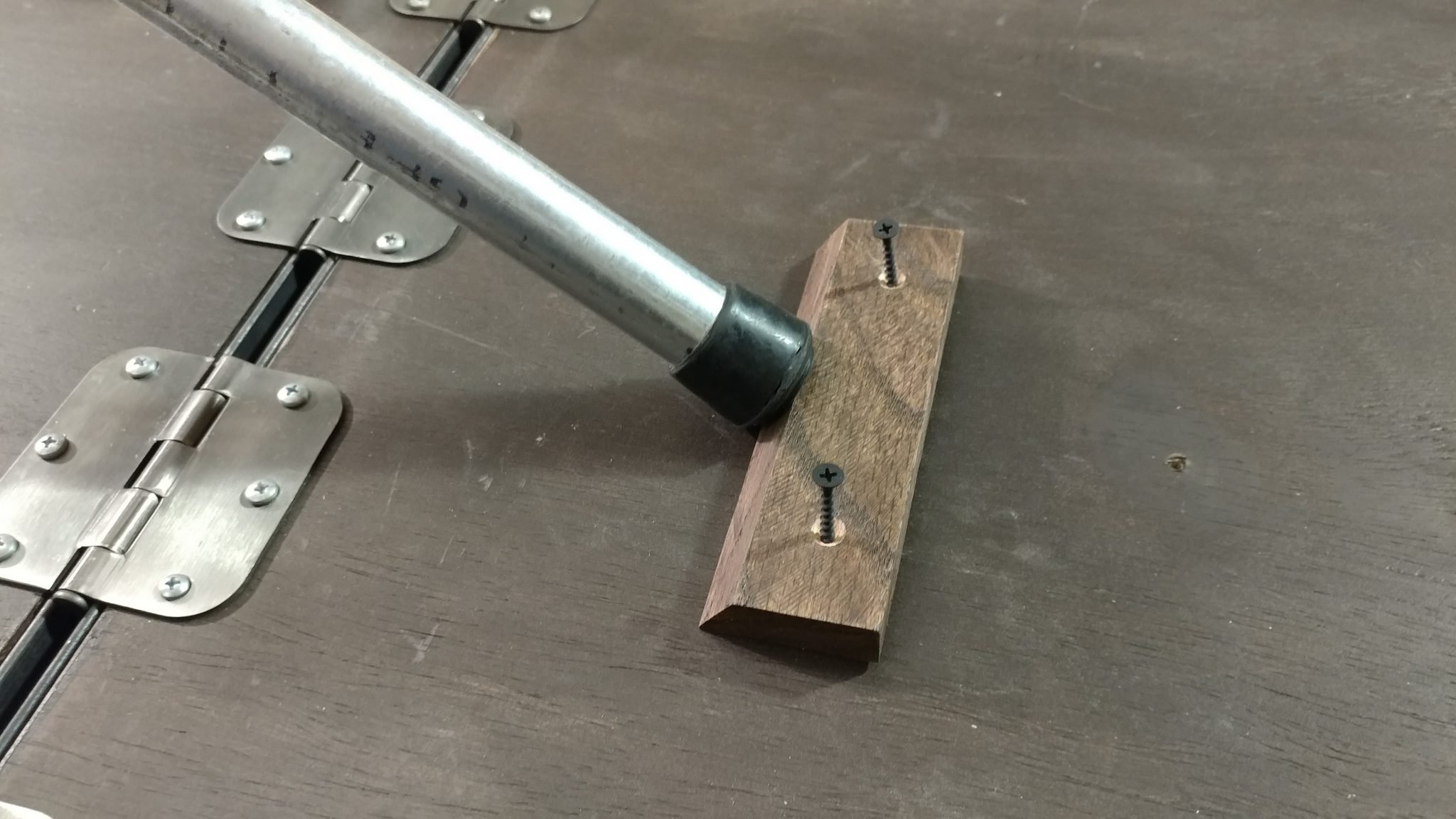
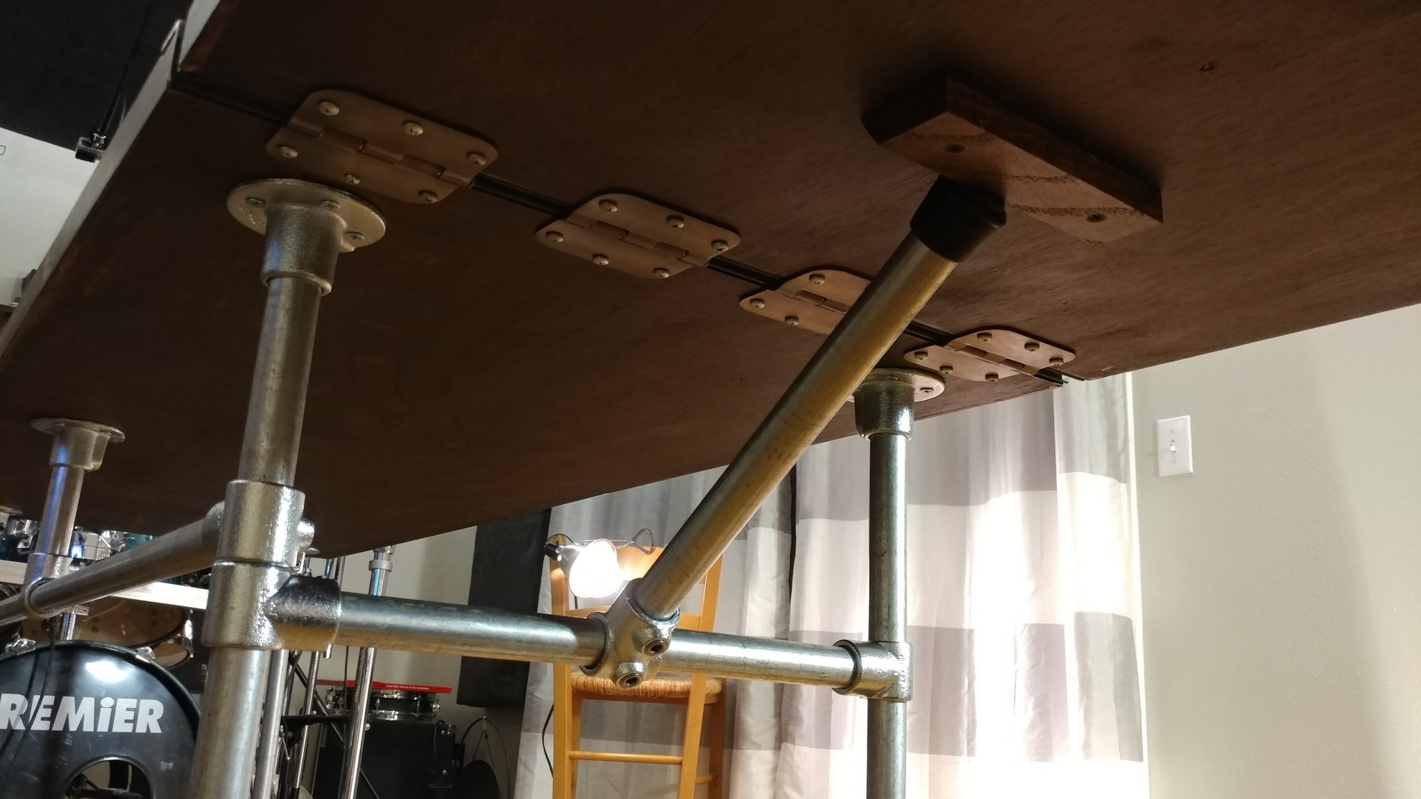
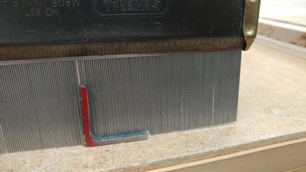
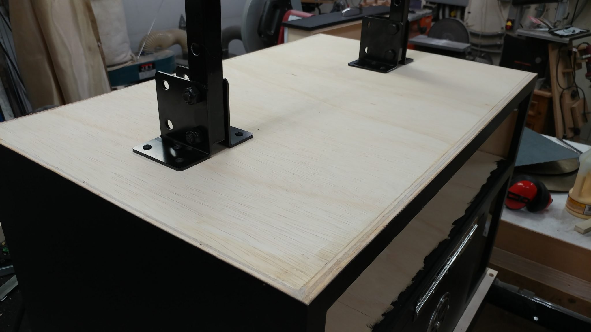
I Chose where I would install the legs to the enclosure. I used my combination squares to align them. This allowed me to easily position each leg so they match.
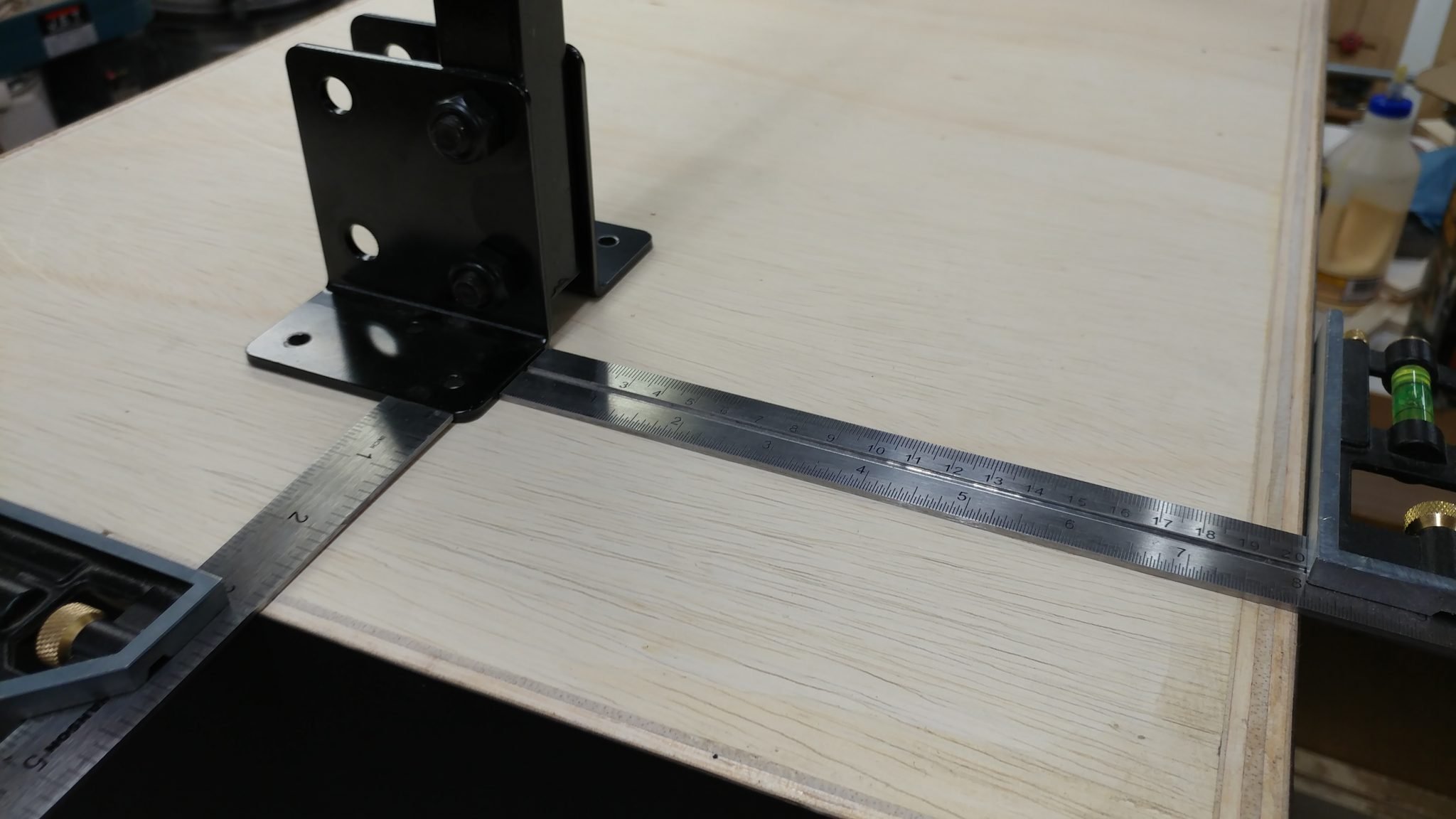
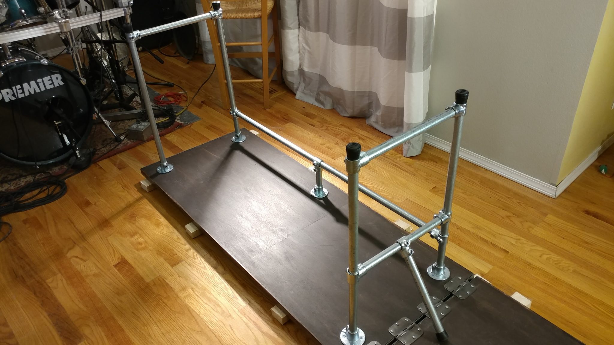
Both legs are now attached.
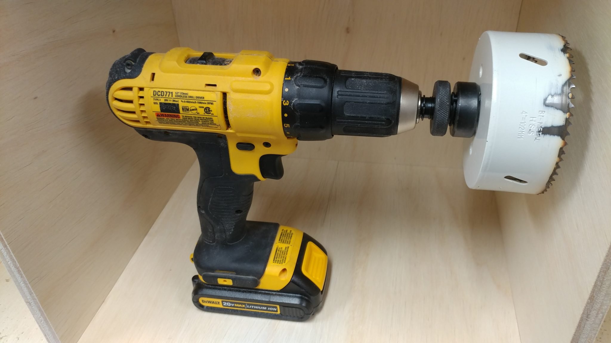
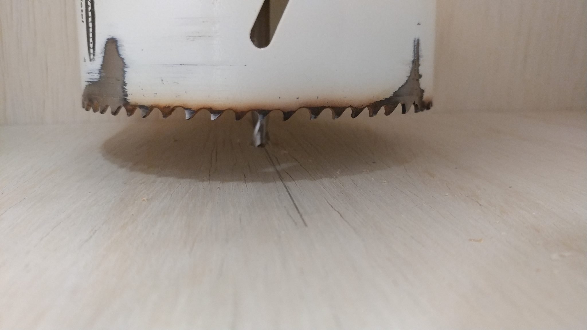
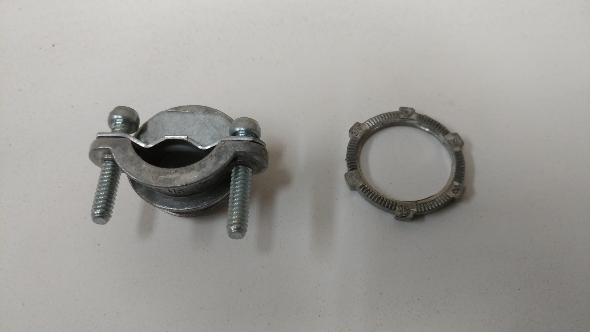
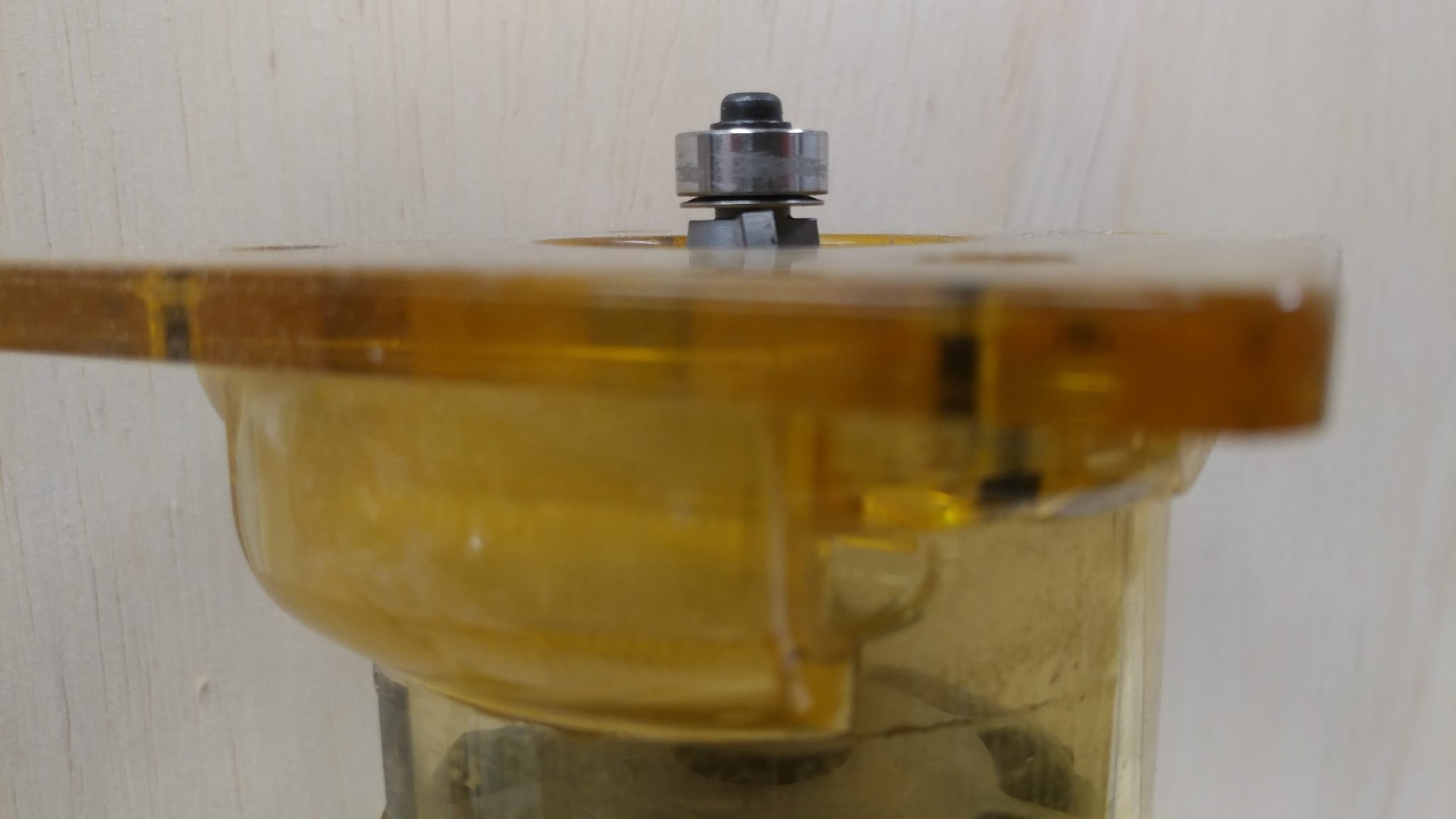
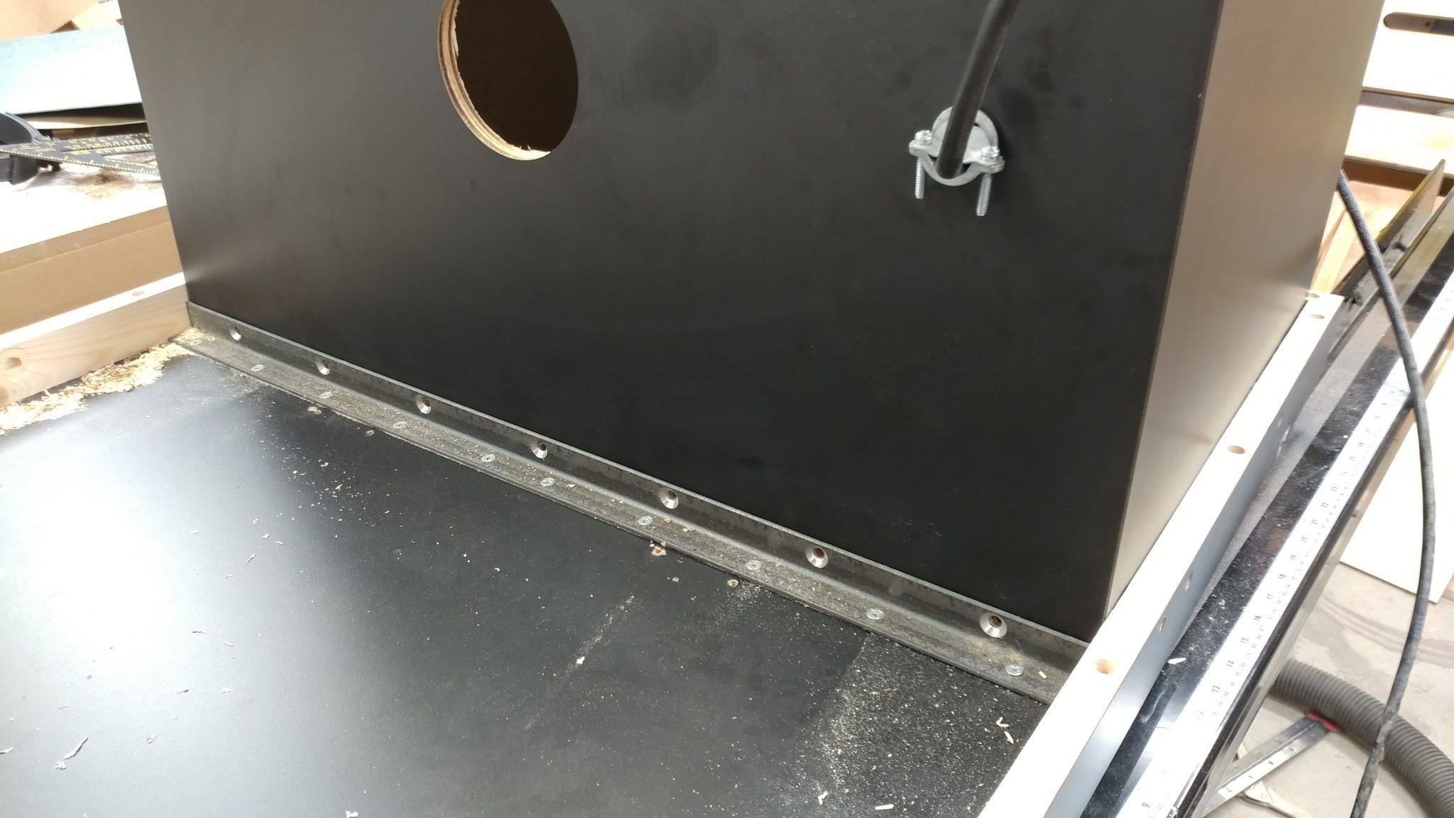
So close! Only one thing left to do before I actually attach it to the saw which is to install a dust port. I’m using a 90-degree port which will allow me to angle it to the back of the saw if I choose to down the road sometime.
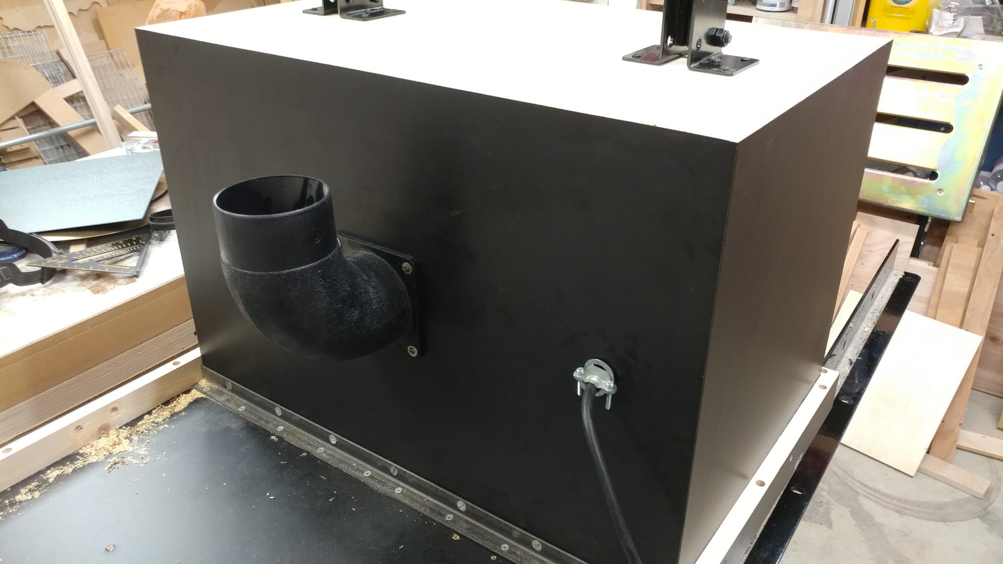
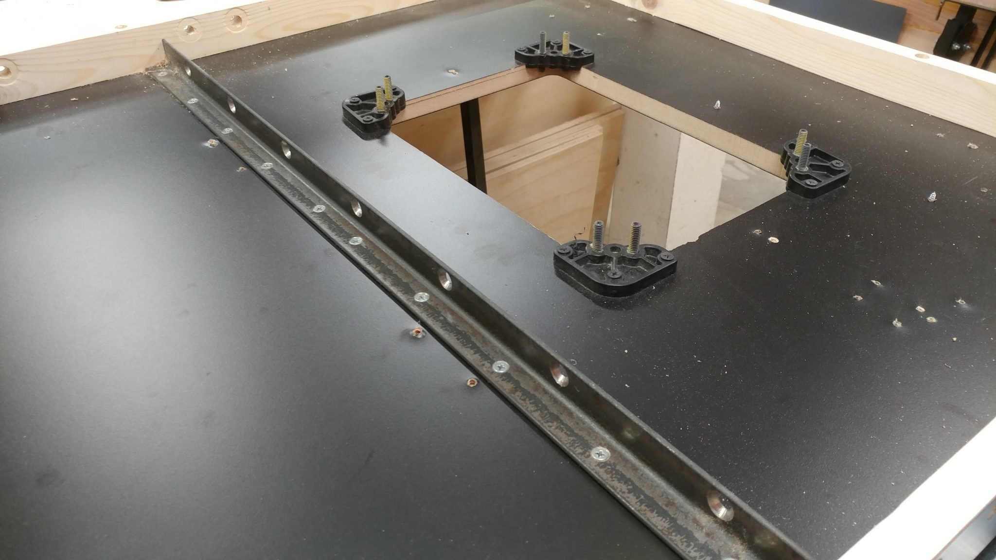
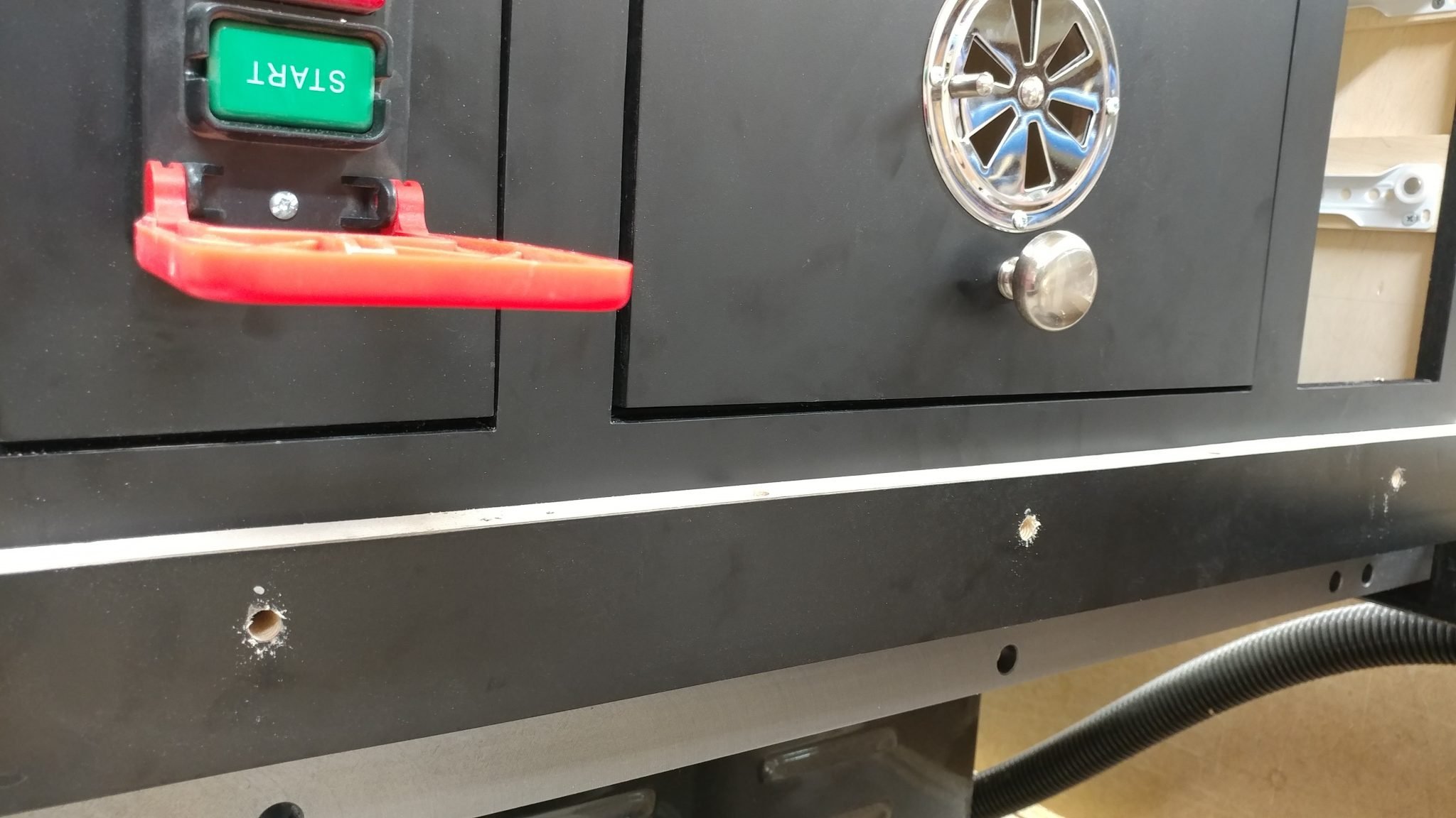
I could finally attach the extension table to the saw. I used longer bolts than the ones provided by SawStop to go through the rails, the extension table, and the enclosure.
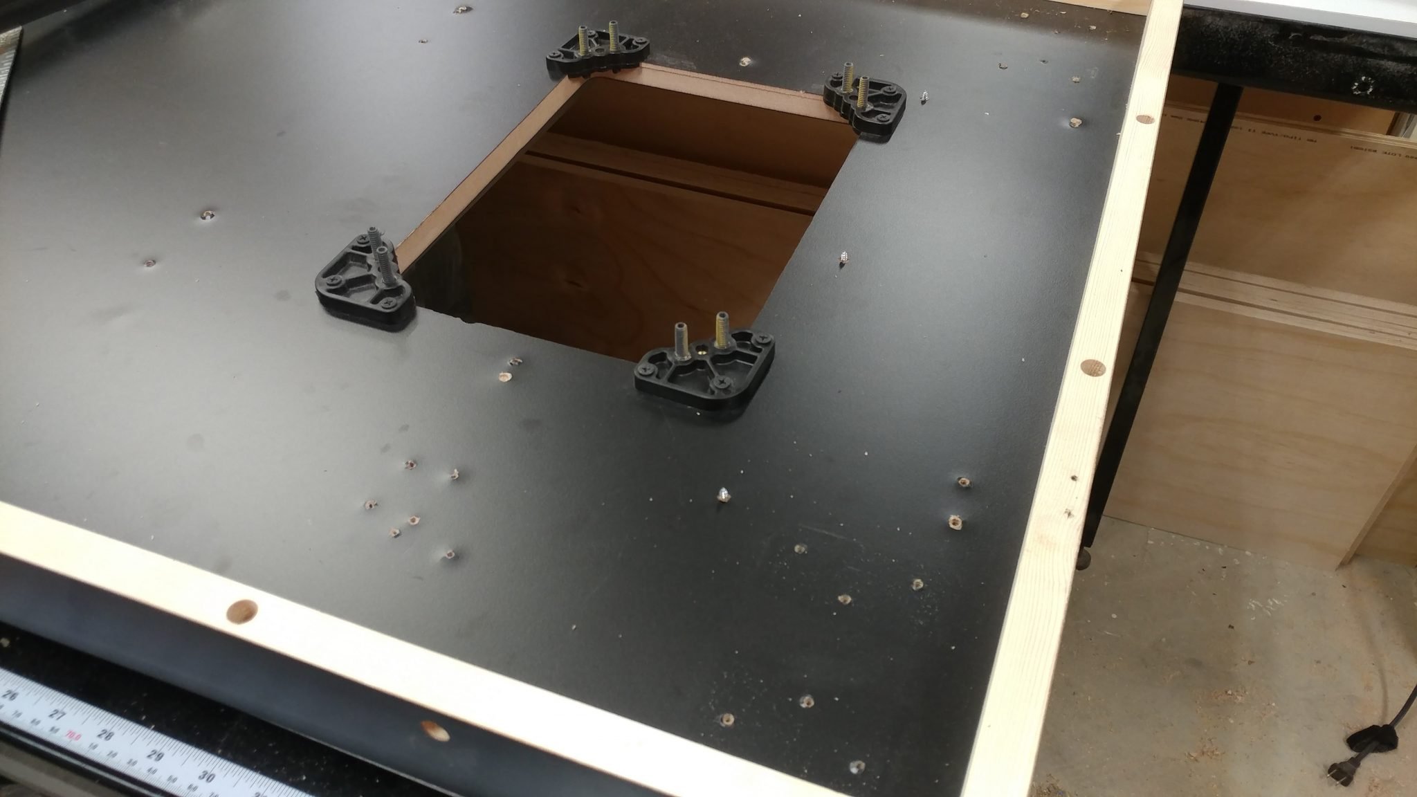
I inserted put the router lift in and tried it out. It works perfectly.
That pretty much covers it.
If I had it to do over again, I would do something different to the outlet faceplate in the main cabinet. The cover for it, which I intended to keep closed while the router is plugged in is too shallow so unless I change the plug on the router power cord to a right-angle version, I can’t keep the faceplate closed while the router is plugged in.
Also, I would probably just make an entire new table that has all of these features built-in, rather than reusing the existing table.
One last thing I would do differently is that I would use better drawer glides. I always have trouble getting the euro-style glides installed squarely so the drawer face is flush with teh rest of the cabinet.
If you have any questions or suggestions, please leave a comment below.
<< Back to Table Saw Modification – Router Table Enclosure: Part 2 – Laminate.
<< Back to Table Saw Modification – Router Table Enclosure: Part 1 – Carcase.