Tool Maintenance – Protecting A Cast Iron Tabletop

Materials Needed

  1. WD-40
  2. Grey Scotch-Brite Pads (7448)
  3. Some sort of treatment such as…

Optional

  1. 0000 Steel Wool (instead of the Scotch-Brite pads)
  2. Denatured Alcohol
  3. Bag Of Rags
  4. Blue Painters Tape
  5. Blue Shop Towels
  6. Hand Pad Holder or Sanding Block

Setting Up

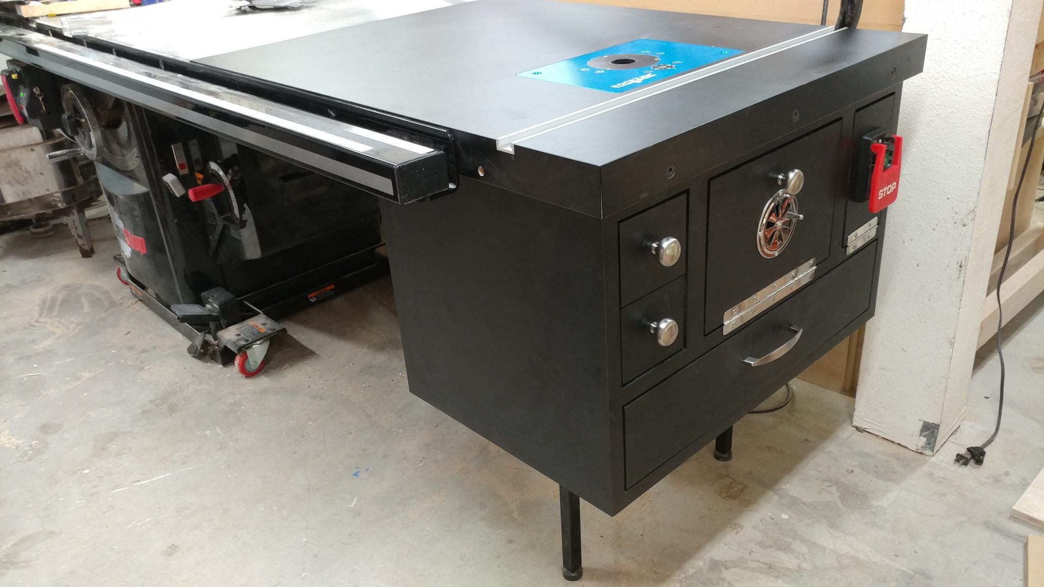
Cast iron gets rusty.  Period.  You can take steps to help prevent it but you’ll still have to deal with it eventually.

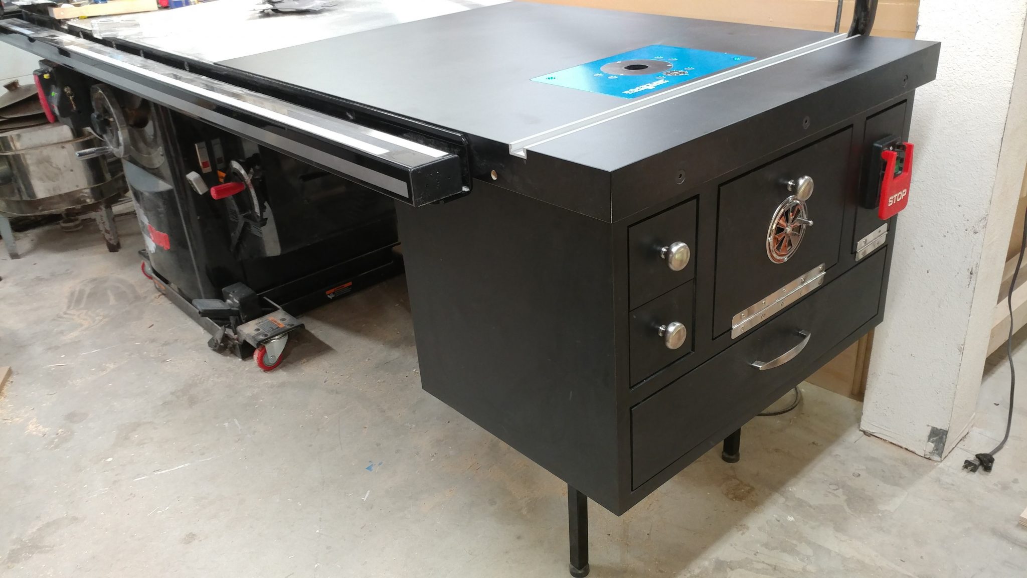
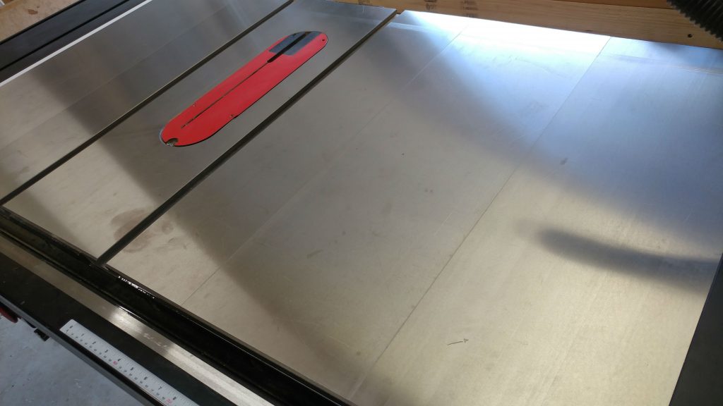
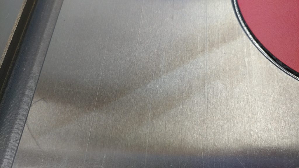
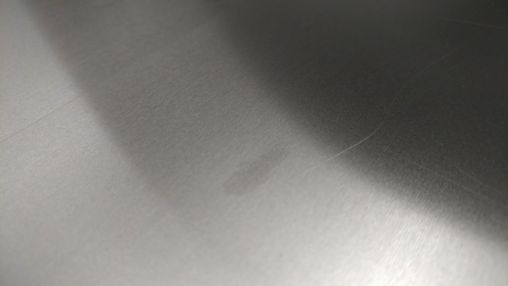
In my case, I have a SawStop Industrial Cabinet Saw with an additional 10″ cast iron wing that has some rust forming on it.  It’s not too bad but I should definitely do something about it.  You can see a big greasy hand print right on my right miter slot.  (How that happened is a long story but rest assured, our lights work now.)

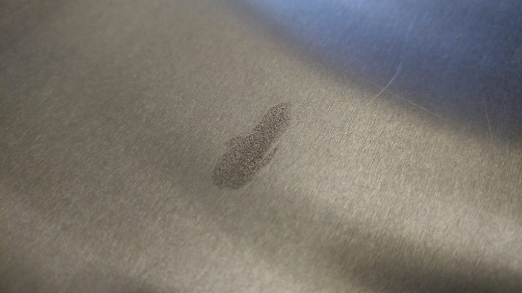
A close-up of the hand print shows that it isn’t pitting yet so it should mostly come off.

The paw prints are a bit more severe.  I don’t see any pitting but I won’t know for sure until I scrub it away.

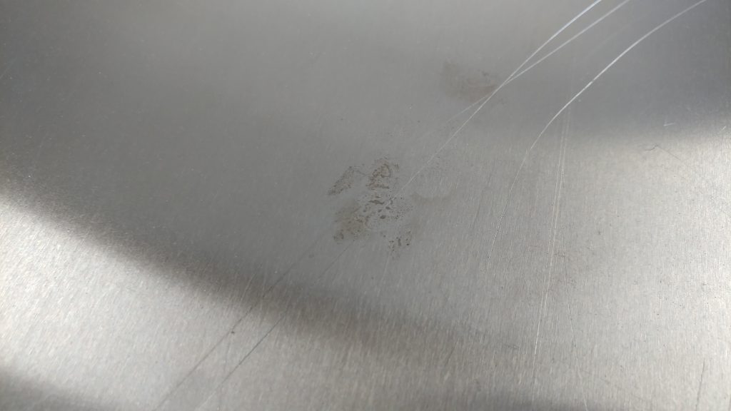
Here are a few more paw prints.

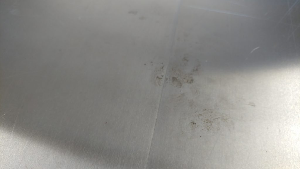
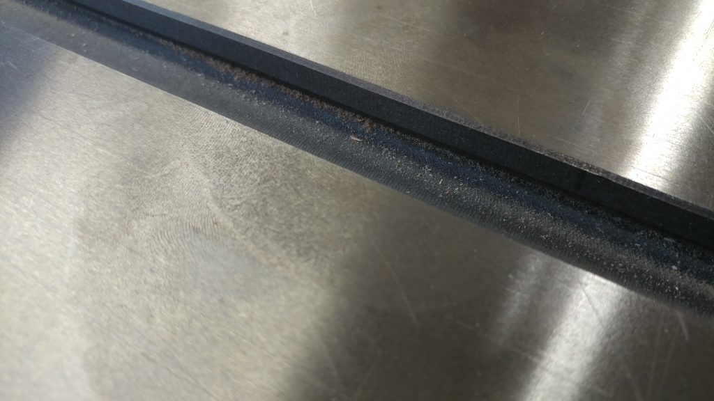
I don’t know exactly what caused these rust bands but I am assuming that this is from moisture being locked under boards that sat on the table top for a day or two.  This is why you shouldn’t leave wood sitting on cast iron overnight, especially during the summer.

Another mysterious rust spot.  It isn’t too bad so it should mostly come off.

Removing The Rust

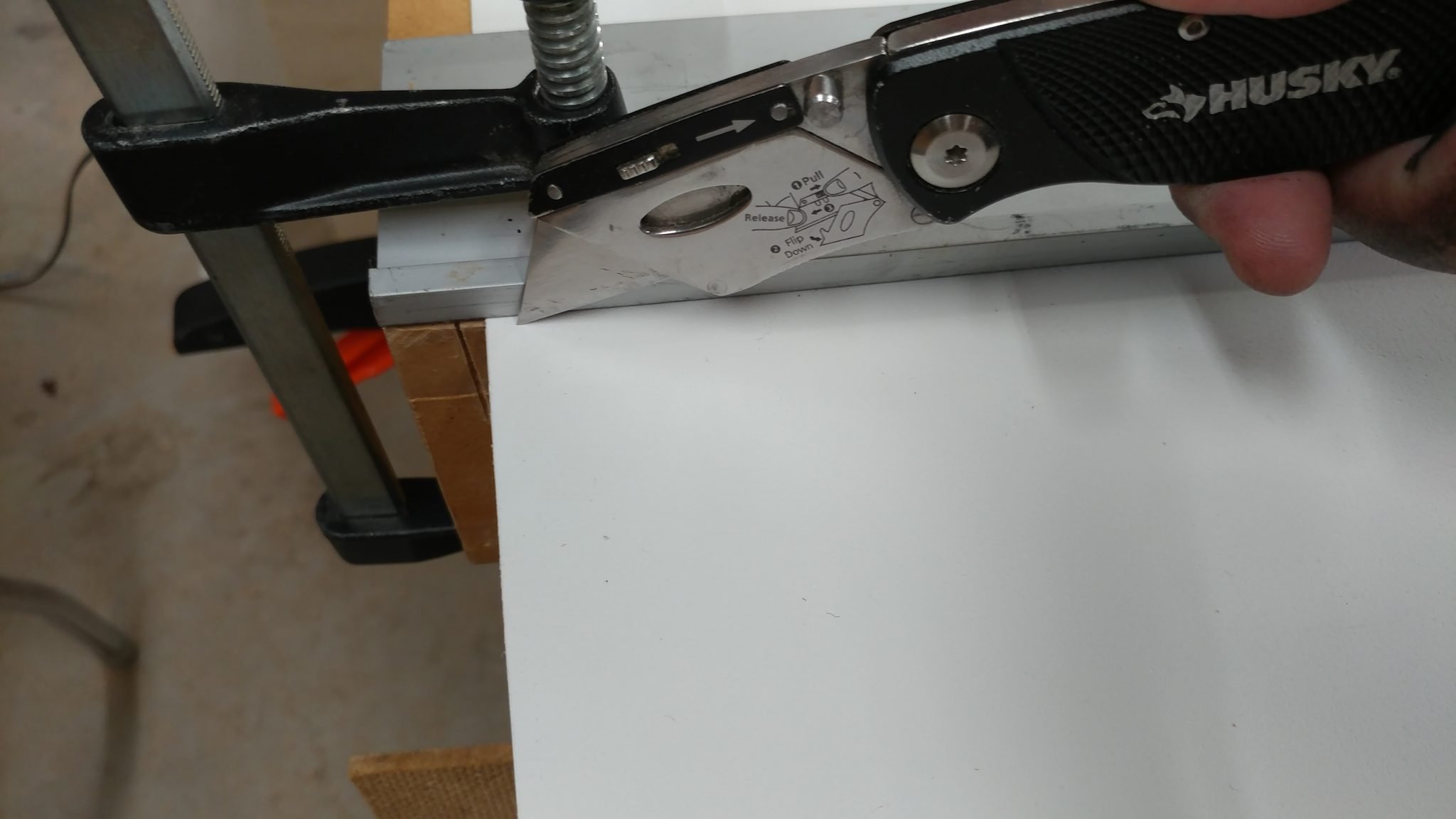
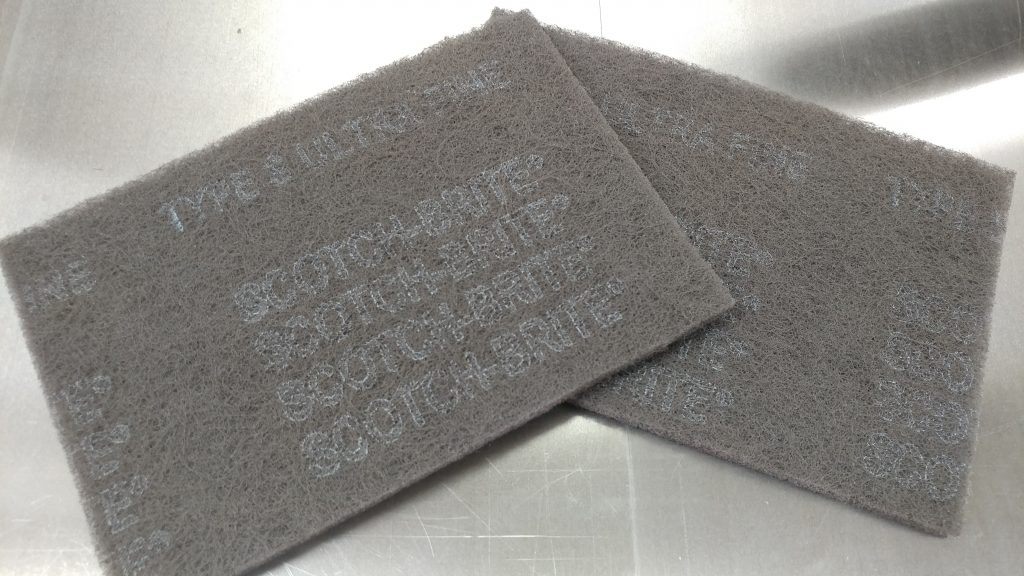
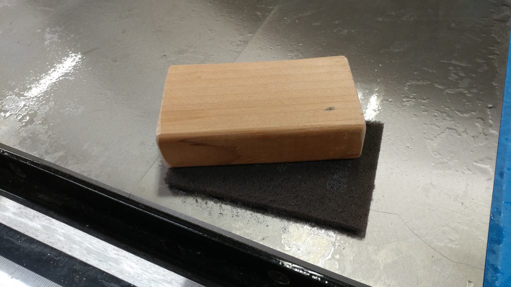
Some people prefer to use 0000 steel wool to remove rust, and it will do a pretty good job.  Personally, I prefer to use Scotch-Brite 7448 pads.  These are the grey pads, not the green ones you use in your kitchen.  They are the same grit as 0000 Steel Wool but you can use a sanding block to apply even pressure over the entire pad.  This is a lot harder to do with steel wool.

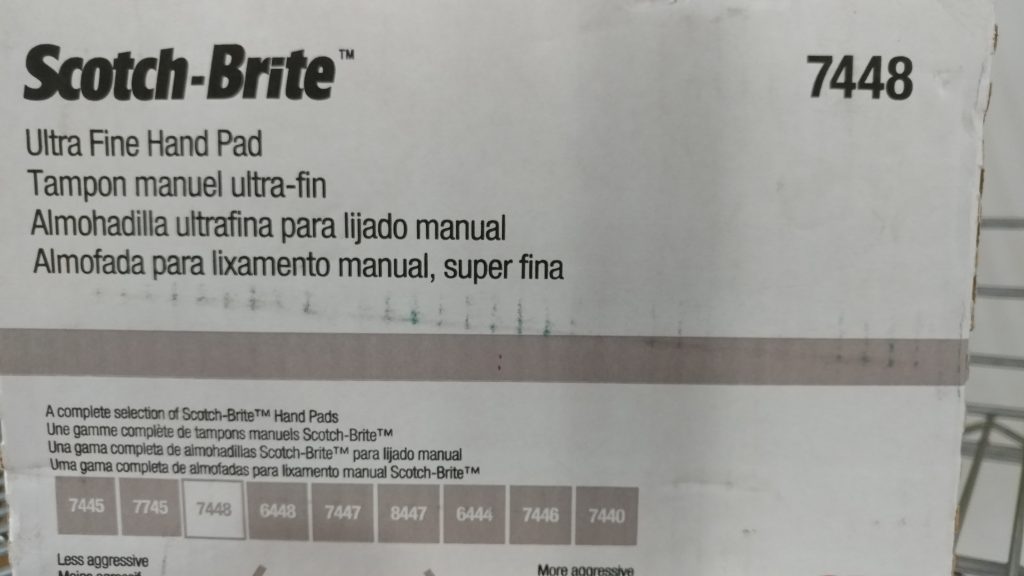
The grey Scotch-Brite pads are pretty big so I prefer to cut them in half.  A box of these will last a long time and can be used on pretty much any tool with a cast-iron top.  I also use them for woodturning in place of steel wool.

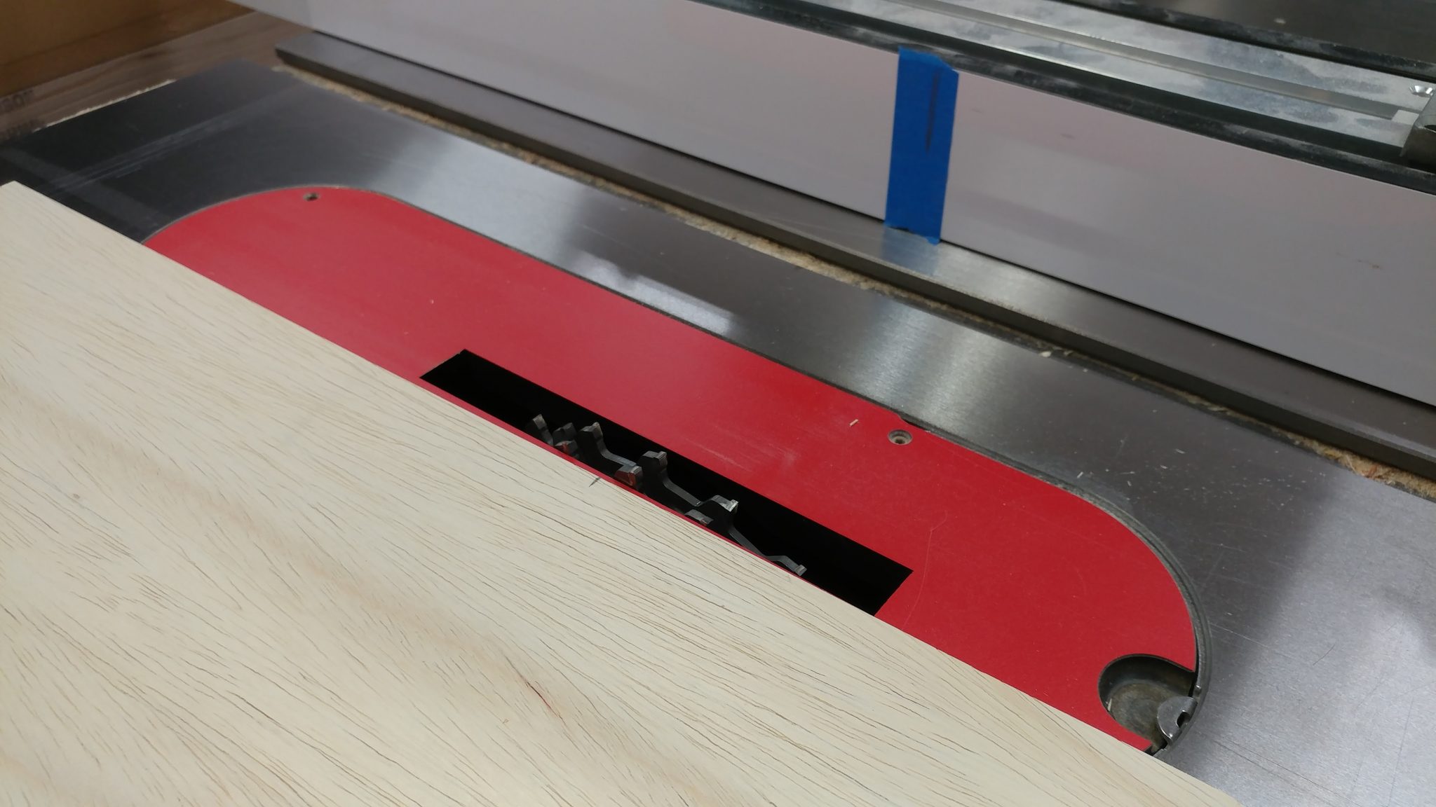
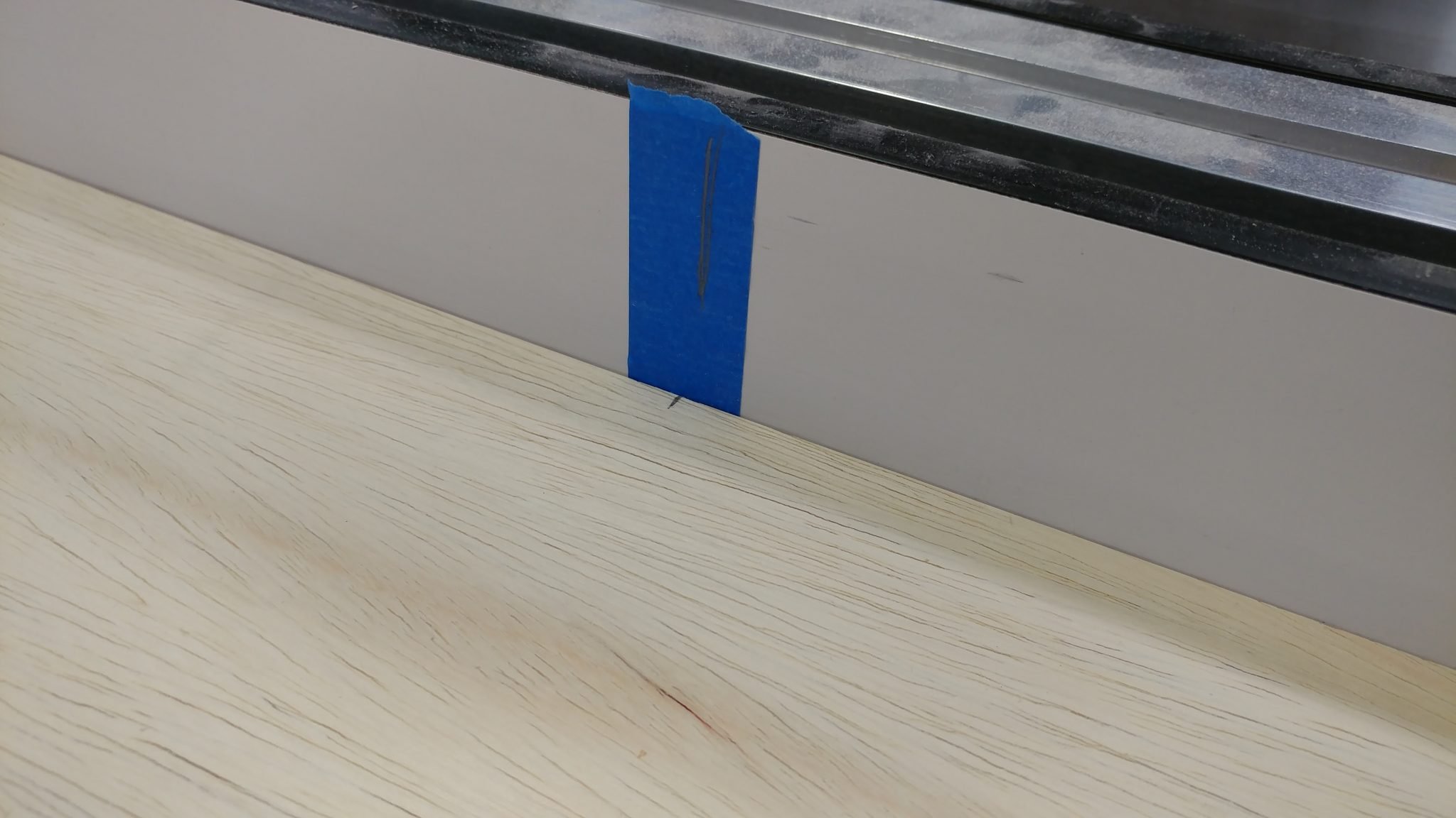
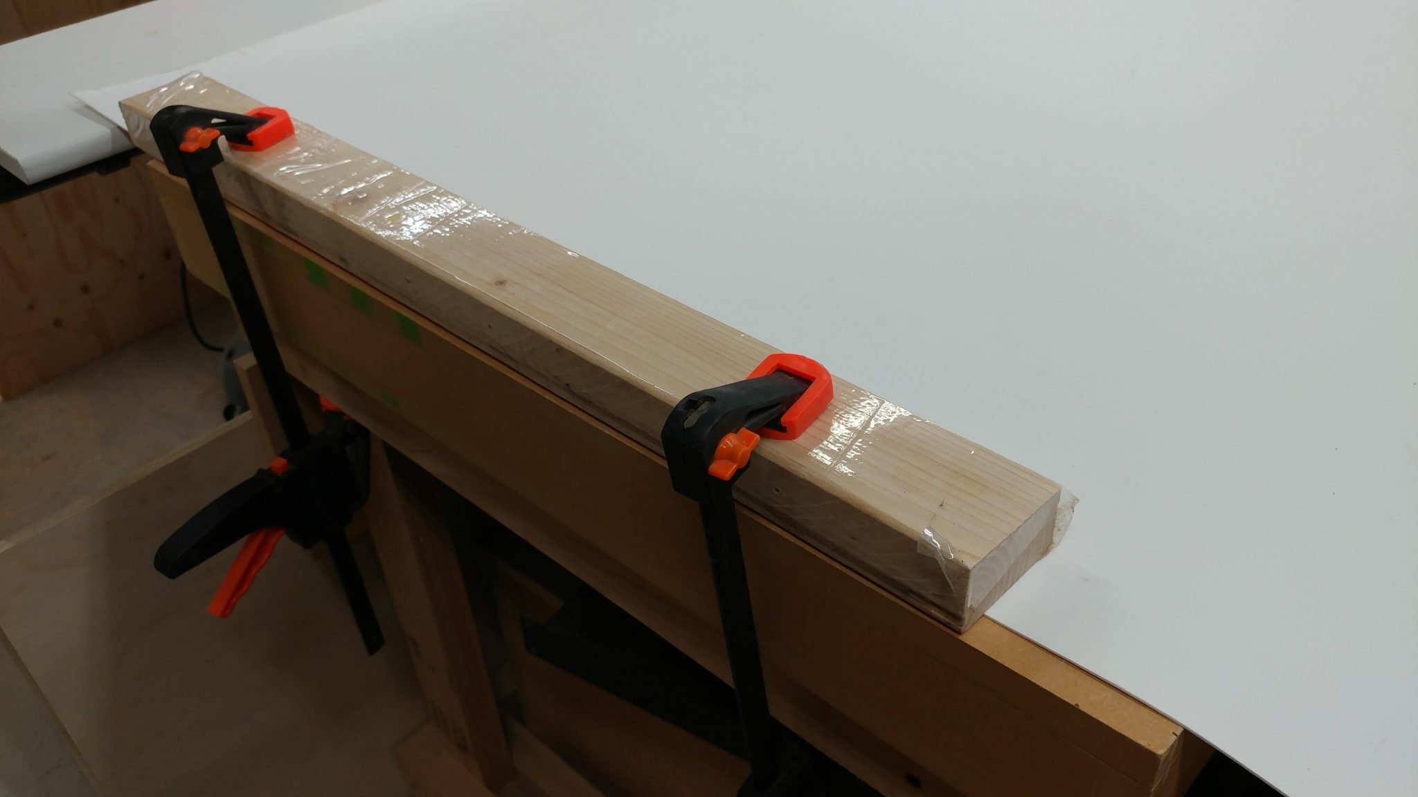
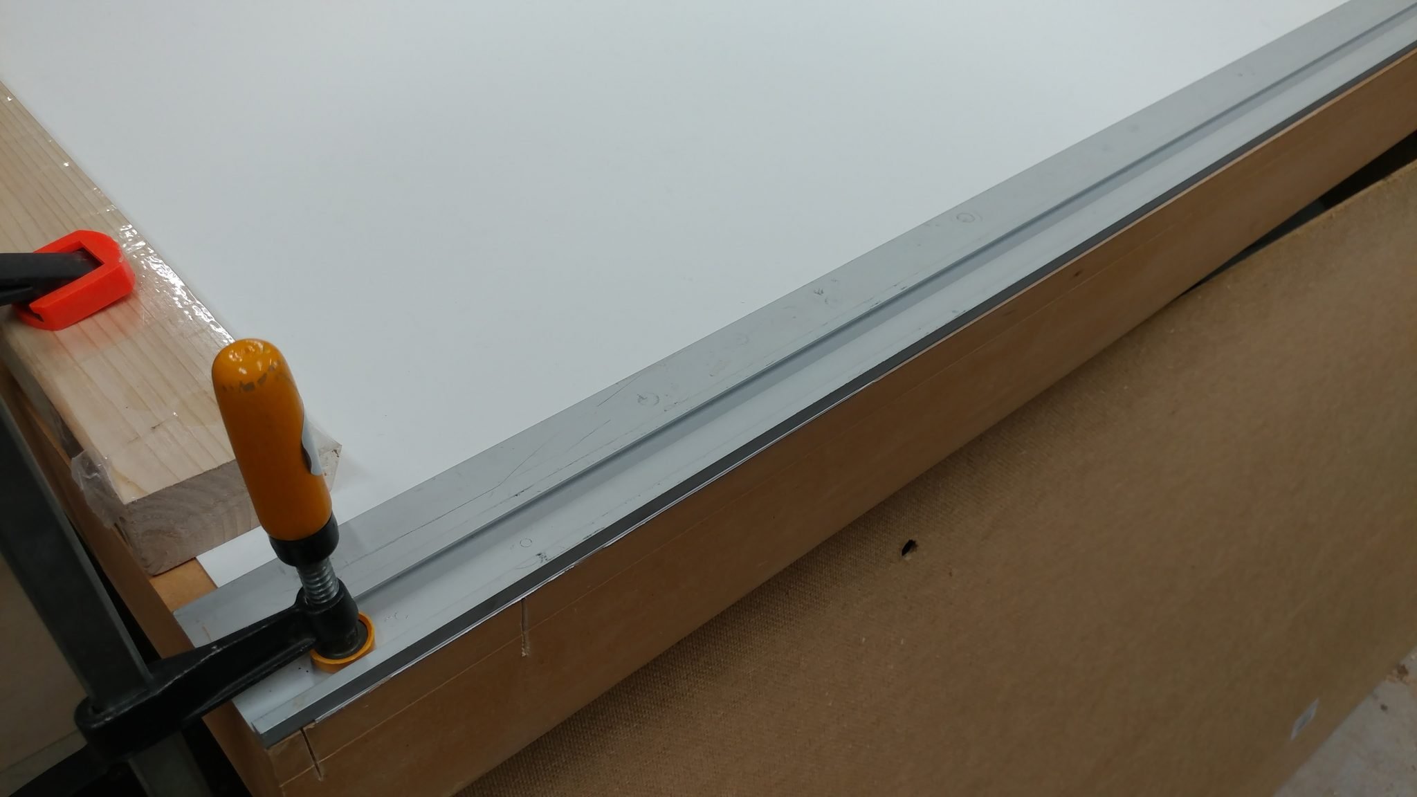
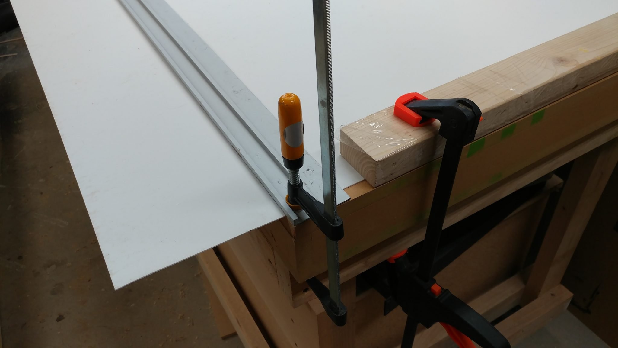
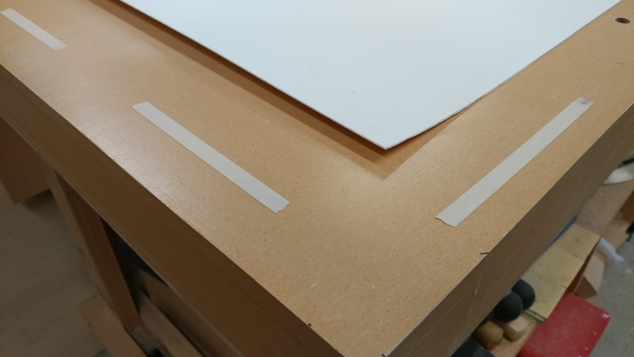
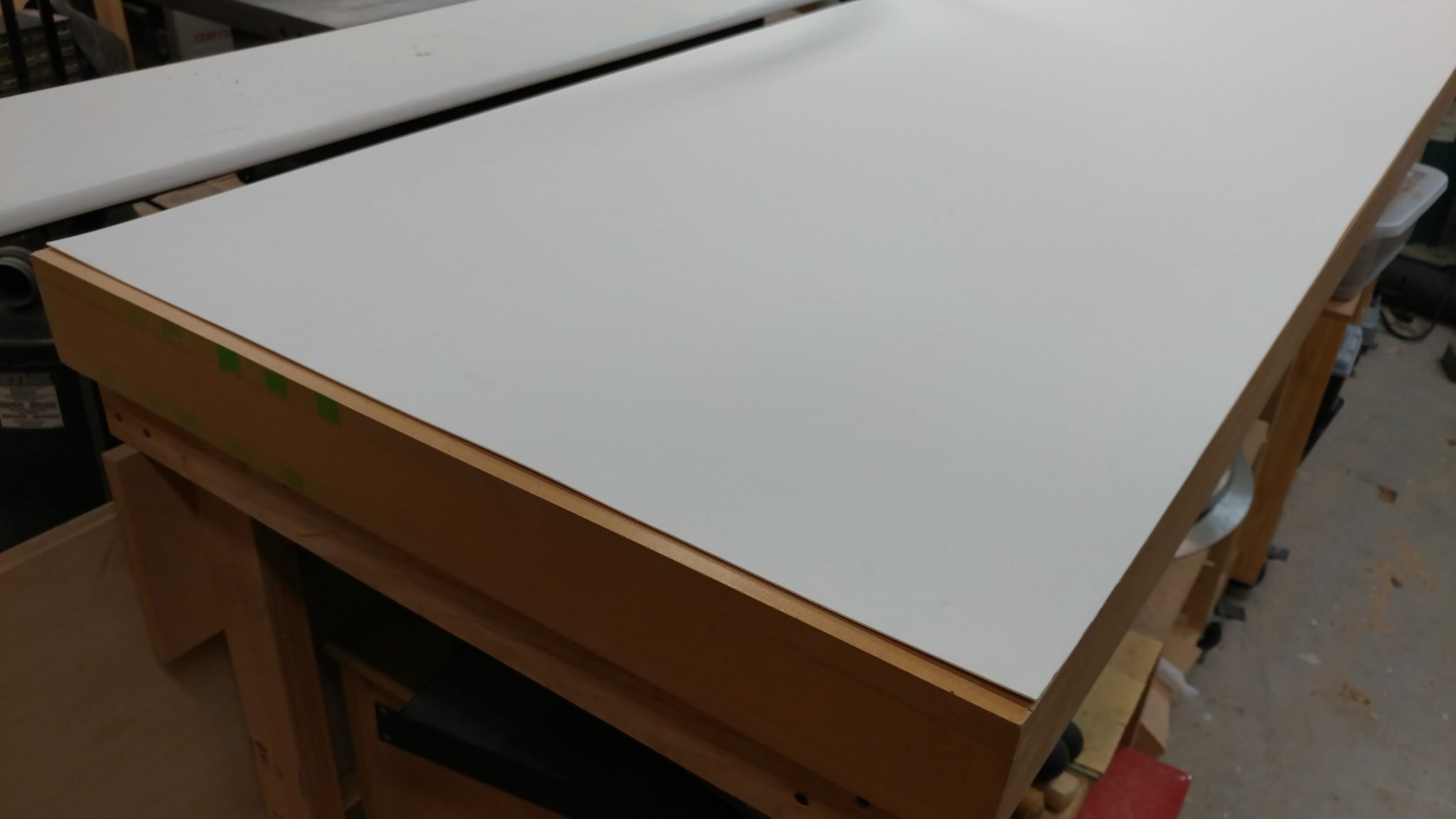
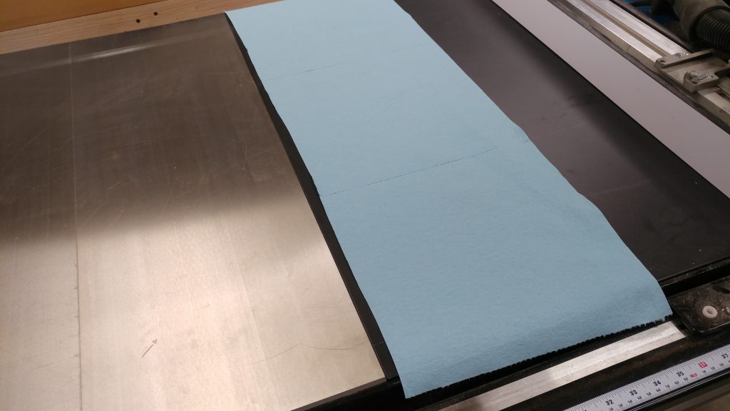
I’m going to be applying WD-40 and it tends to splatter.  I’m not a big fan of getting that gunk off of my wooden extension table so I am going to tape it off to protect it.  I start by laying down some blue shop towels along the edge of the extension table.

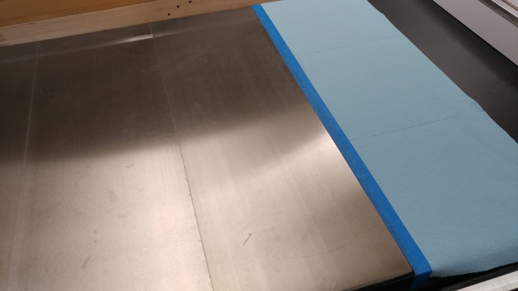
I then use some blue painters tape to mark off the end of the extension table and secure the shop towels down.  This should help protect it during the next step.

Next, I apply a generous coating of WD-40 to the entire table top.  You want to let it sit for a while so it can penetrate the iron and start to break apart the rust and even some of the slight discoloration that cast iron can sometimes get.  I will typically let it sit for at least 15 minutes but in this case I let it sit for about an hour and a half.

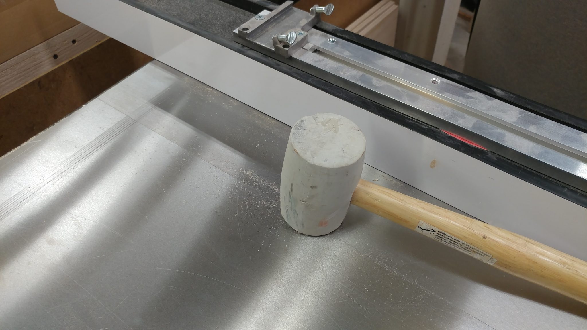
After it has sat like this for a while, I take my grey Scotch-Brite pad and a hand pad holder, or in my case I just use a scrap block of 2 X 4 and start scrubbing.

You should scrub in a front-to-back-to-front motion.  Try not to focus on one little spot since that will lead to an inconsistent shiny spot.  Instead, use some elbow grease and cover the entire depth of the cast iron.

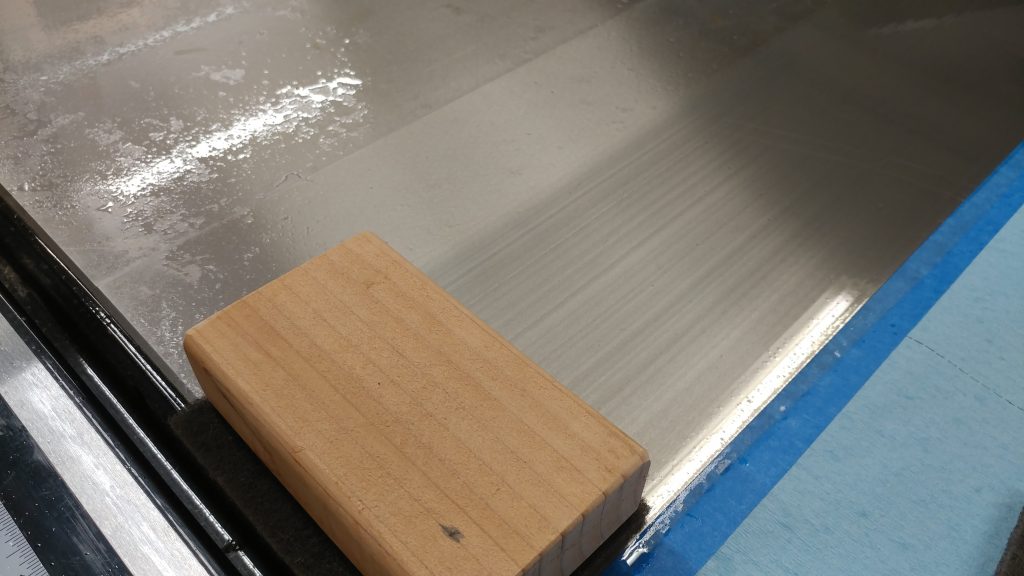
I like to scrub until I at least get a dark slurry started.  It will typically require more scrubbing if your table top is as rusty as mine was.

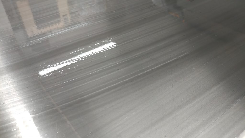
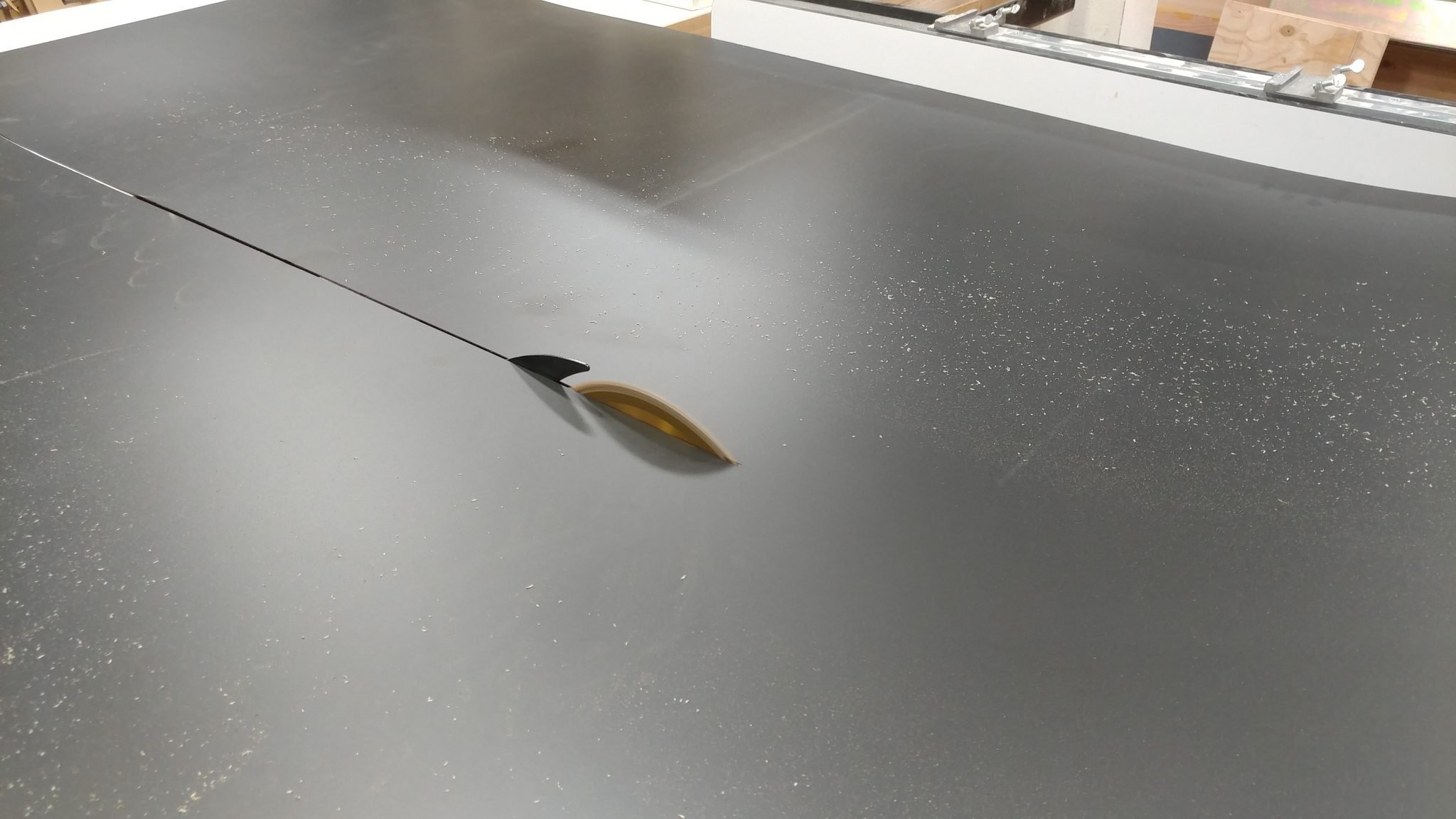
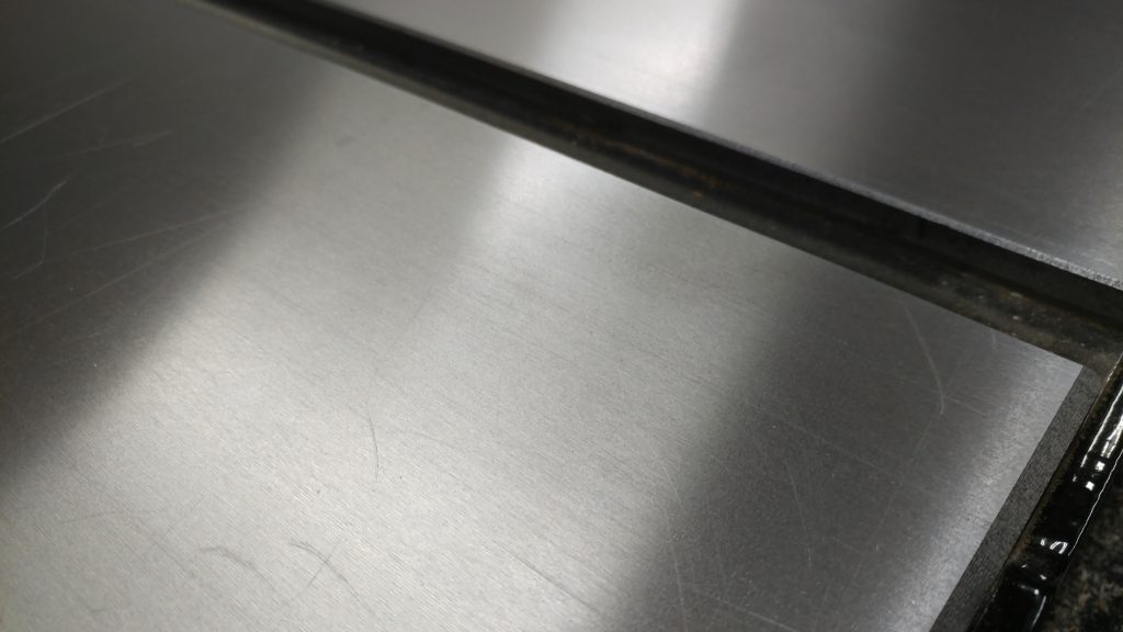
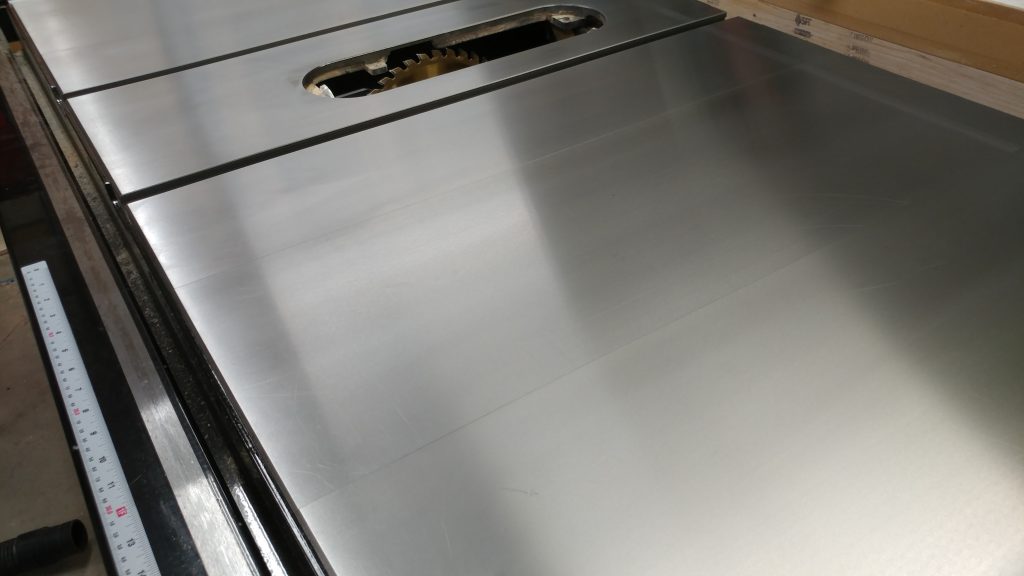
After tackling the entire table top, I do the bulk of the clean-up with blue shop towels.  The table top should look a lot better at this point.

If rust sits for a while it can permanently discolor the cast iron.  You can see this here.  The rust is gone but the iron is stained.  Personally, I’m cool with this.  It doesn’t affect the usability of the saw.

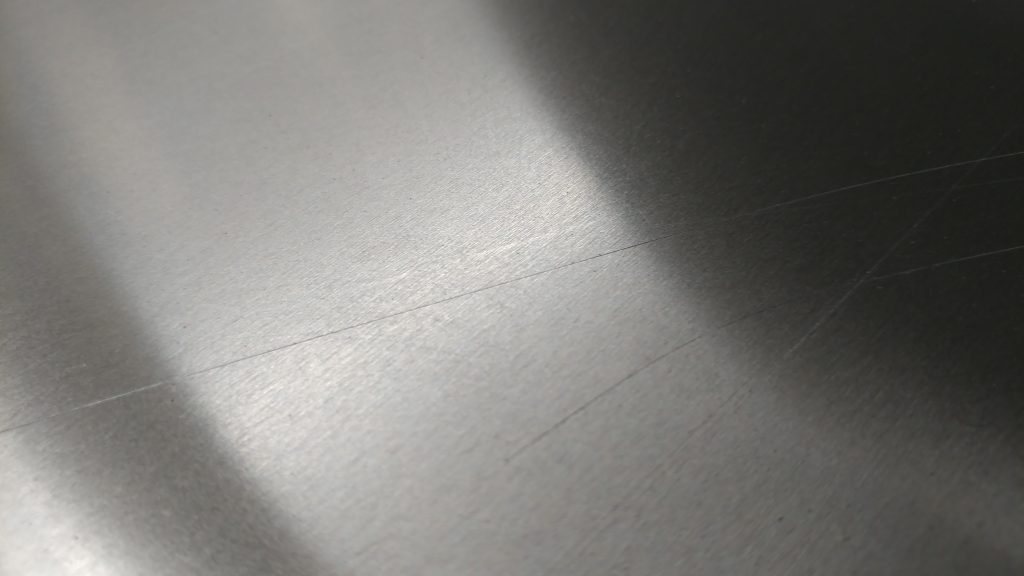
The hand print is mostly gone.  I can still see a slight shadow but you have to know it’s there in order to see it.

Surprisingly, the paw prints are completely gone.  I thought these were going to be there forever.

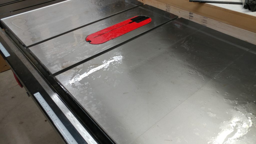
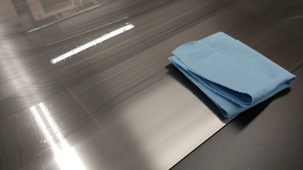
Technically, you can stop here.  I find that no matter how much I scrub with shop towels I can never quite get all the WD-40 up.  This leaves a slightly greasy feeling to the table top which can transfer to the material you are cutting.  I find that the best way to clean this up is with denatured alcohol.

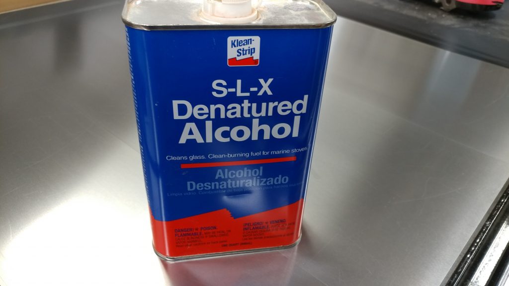
I start by pouring some denatured alcohol on the table top.  This picture may be cringe-worthy but worry not.  This won’t cause your table to get rusty at all.  Then, use a shop towel to wipe it all up.  This should get the rest of the WD-40 off the cast iron.

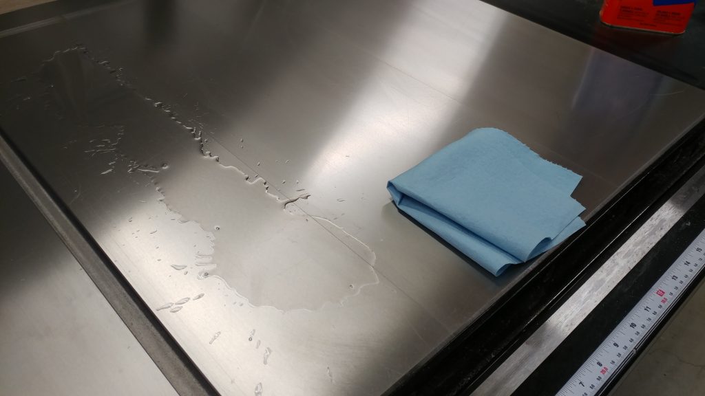
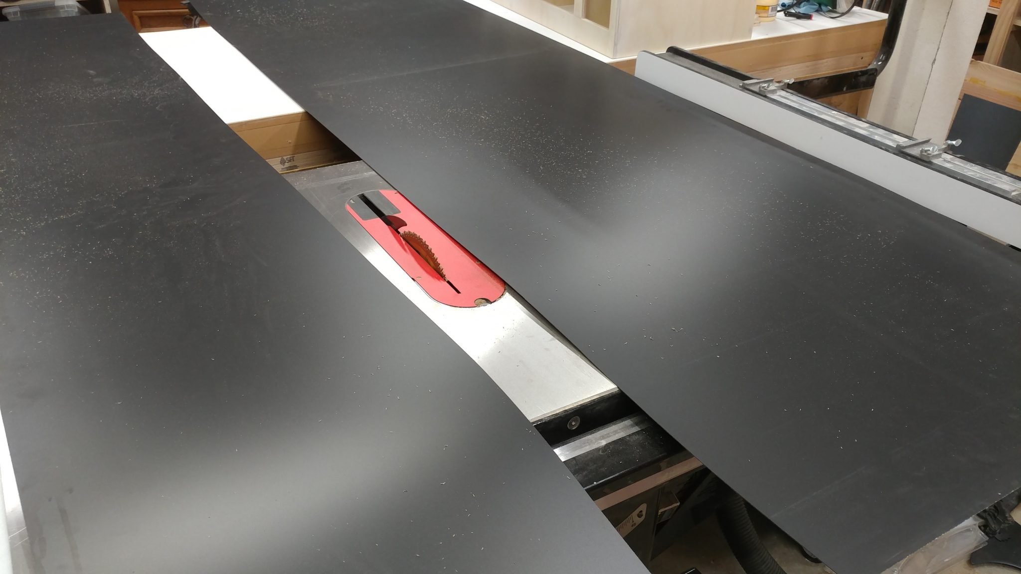
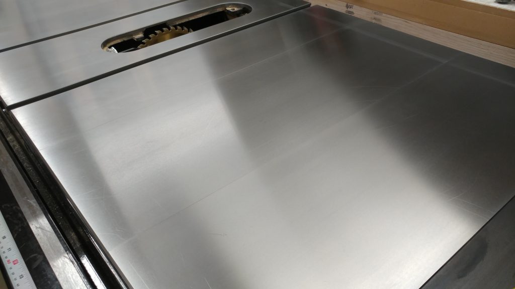
The cast iron is now completely exposed and needs to be protected.

Protecting The Surface

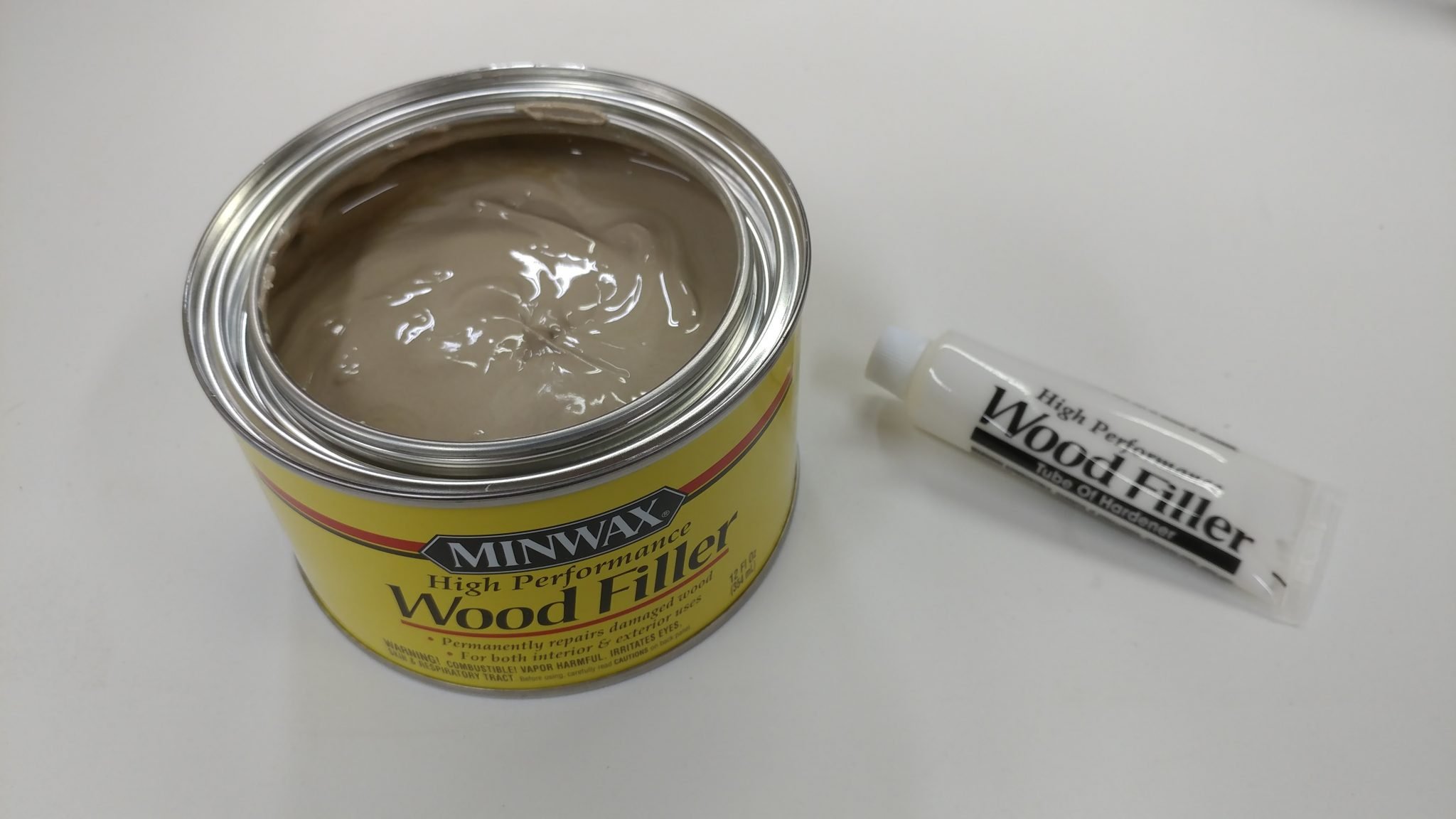
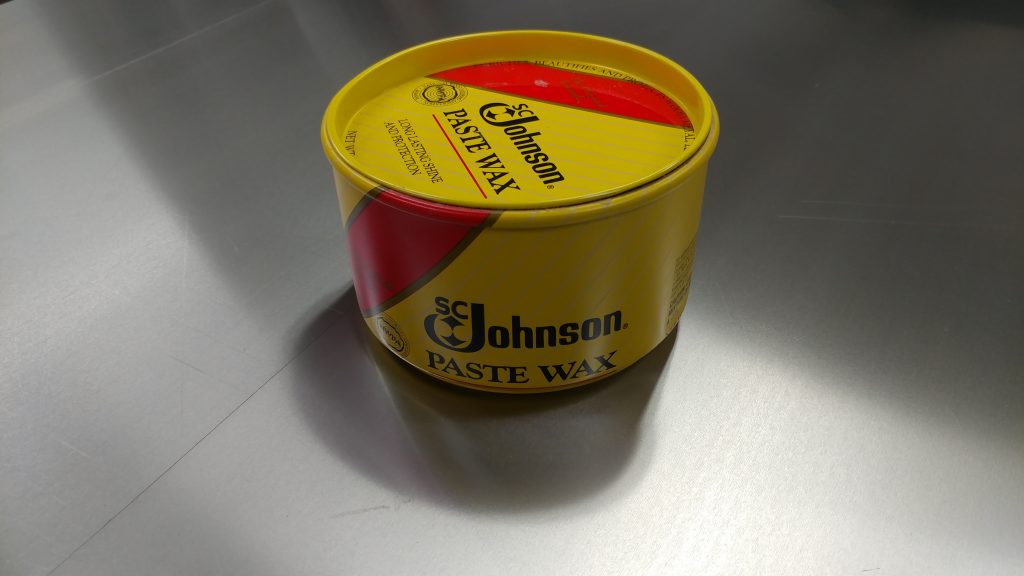
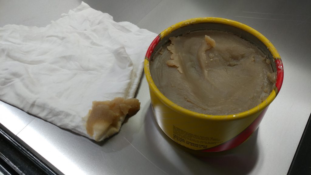
There are many ways to protect the surface of cast iron tools.  I’ve had good experiences with T-9 BoeShield or GlideCote, but I personally prefer using a furniture wax like Johnson Paste Wax, although MinWax and Renaissance Wax will work as well.  I like Johnson Paste Wax since it is softer, which means it applies easier and also buffs out a LOT easier than either MinWax or Renaissance.

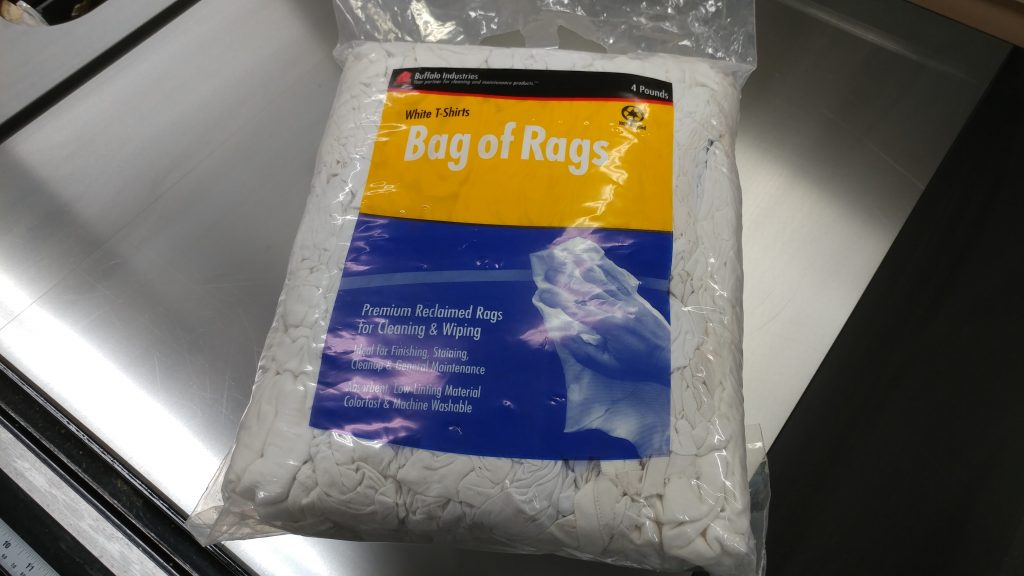
You can use shop towels to apply the wax but you’ll have better luck with a cloth rag.  I try to always keep a Bag of Rags on hand.  These are just scraps of white tee shirts so if you have any shirts you’re just going to throw out you can use them for this instead.

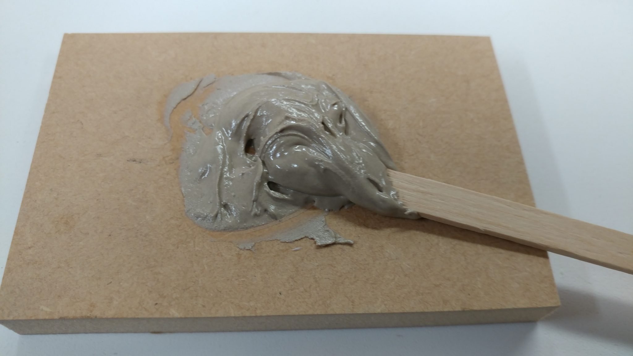
Use the rag to scoop up a generous amount of the paste wax.

Apply the paste wax to the cast iron.  You don’t need to apply it in any particular fashion, just be sure to get it all over.

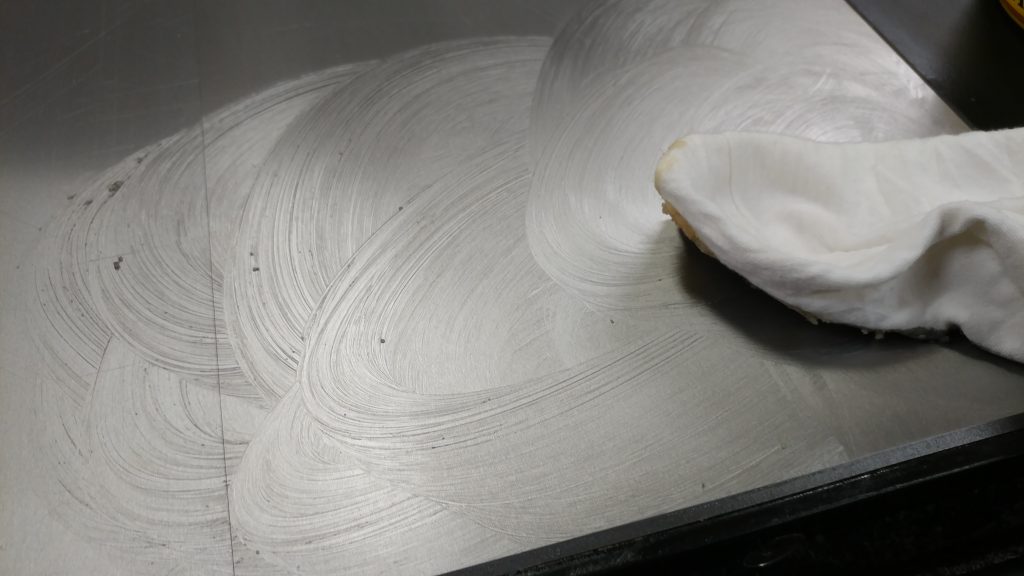
After you have the table top coated, let it sit for a while.  I usually let it sit for about 15 minutes.

You’ll know it’s ready to buff out when the paste wax gets a cloudy look to it.

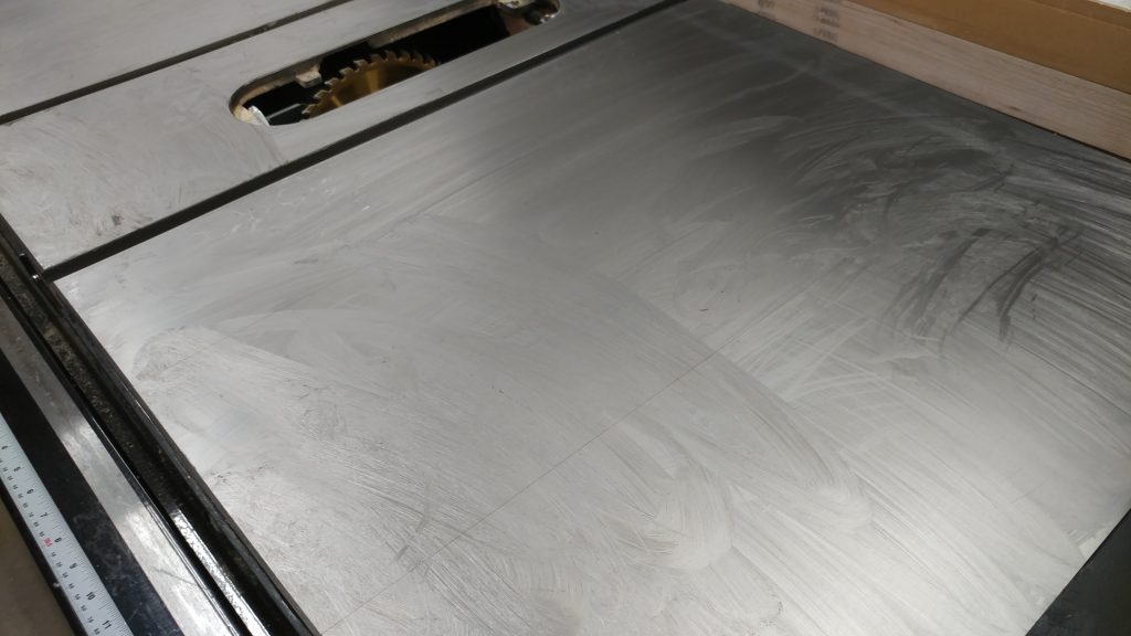
Use a fresh rag to wipe the wax off and buff it out.  This can take some experimentation but the way I handle it is to use one rag to wipe the bulk of the wax off but I don’t worry about it looking good yet.  You’ll still have some streaks and maybe a few missed blobs of wax.  After that, I take another fresh rag and wipe it down to buff it out.  You’ll notice that when you first start buffing it, the table will be slightly “grabby” with the rag.  Just keep buffing.  You don’t really need to apply much pressure or buff in any particular direction, just go back-and-forth for a while to build up some friction.  You’ll find that eventually the table will get very slippery.  That means you’re done and ready to move on to the next section.

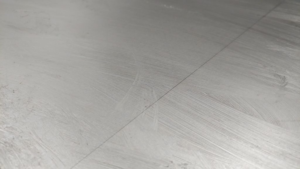
After you finish, I recommend that you apply at least two more coats of wax.

That’s it.  You’re done.  You now have a nice slippery cast iron table top that won’t rust up as quickly (if at all).  I like to repeat this process as needed, which may be every six months or every six years.  It all depends on how you use your saw.

Also, it is a good idea to apply some paste wax to the exposed metal on the front tube where the fence rides back and forth.

News – June 5th, 2017 – Recording Progress

Recording Progress – Bright & Shiny

This weekend I managed to get time to record two more songs for Bright & Shiny.  The two songs are titled This Waiting and The End Holding Your Hand.

I was particularly happy to get The End Holding Your Hand recorded because of how I go about recording.  While I am working on a song, I listen to it repeatedly while I drive to-and-from work each day.  I use that time to write out different parts and memorize the structure of the song.

Unfortunately, I don’t get many opportunities to actually record since I need to get the family out of the house.  This means that I may sometimes end up listening to a song quite a bit before I get to actually record it.  In the case of this song, I listened to it repeatedly for over three weeks.  As you can imagine, I was pretty damn sick of it by the time I got around to actually laying down the tracks.

When I record, I also film.  I am working on videos of each song to compile into a mini documentary on the recording of the drums and percussion for this album.

I only have two more songs to record then I’ll be focusing on the auxiliary percussion.

Here are rough-cuts of the drum performance videos.  The drum tracks need to be mixed properly and the track I’m playing along with is only a temporary scratch track.  I’ll update them when I get a final mix of the songs.

This Waiting


The End Holding Your Hand


These drum tracks are a little more sparse than I typically prefer but that is intentional since I needed to leave space for auxiliary percussion.

Here’s an example of a song with finished percussion, although it isn’t a final mix.

Soothsayer

News – May 31st, 2017

 Sabian Meet The Masters 2017

My daughter Maisie and I went to the 2017 Sabian Meet The Masters event at Rhythm Traders in Portland, OR.  They had prototypes on display and for sale along with someone hammering cymbals as well as another Sabian employee operating the cymbal lathe.

The main reason I went was to find out a bit more about the turning tools they use with their cymbal lathes.  I was thrown off a bit since the YouTube videos I’ve seen shows what looks like high-speed steel scrapers being used but some of the videos from other cymbal junkies indicate that they use carbides.  It turns out that they use carbide scrapers that look like big popsicle sticks that simply insert into a big handle.  It appears that any carbide cutting tool will work and I plan on trying out this theory later this summer.

Another highlight was getting to meet Mark Love in person.  I’ve seen him in a lot of Sabian videos.  He seems to have one of the coolest jobs.

Maisie and I each picked up a cymbal and Maisie got herself a pair of Ringo Starr signature drumsticks.  She’s a pretty big Beatles fan, which is pretty cool for an 11-year old.

Sabian 10″ Prototype Cymbal

10" Prototype Cymbal

One of the prototype cymbals we picked up was a 10″ B8 conical doohickey.  Since it’s part of the Prototype line, it doesn’t really have a name, but I’ve seen it referred to as a Lamp Shade or just an FX cymbal.  It’s a conical B8 cymbal with a tight lathing pattern on the top and more of a “sanded” texture on the bottom.  There isn’t any hammering at all.  I’m normally not a fan of B8 cymbals but I decided to give this one a try since they didn’t have any of this style in B20.

Last night I got a chance to actually try it out and it actually seems to go well with my 12″ Glennie’s Garbage.  Below is a clip of one of the songs we’re working on.  You can hear the prototype at around 4 seconds and the 12″ Glennie’s Garbage cymbal at around 12 seconds for comparison.

As you can hear, the Glennie’s Garbage has considerably more sustain than the prototype, but that’s to be expected when you go from a 10″ to a 12″ cymbal.  They definitely sound like they belong in the same family.

I’ve seen these used before by Terry Bozzio. particularly in the All Cymbal Drum Set video where he takes two of the same size and tapes them together so they form a diamond.  He takes several of these in different sizes and uses them as “toms” in his all-cymbal drumset.  He does a pretty wicked roll around them starting at about 1:59.


Sabian 16″ Prototype Cymbal

16" Prototype Cymbal

My daughter Maisie picked up a prototype cymbal as well.  Like mine, it’s B8 and doesn’t have any hammering.  It also doesn’t have any lathing but instead has an almost “brick-like” pattern stamped into it.  It actually sounds pretty good for a B8 cymbal.  I haven’t heard it used in a musical setting yet, so it’s hard to make a final judgement.  She seems to really like it and that’s all that matters.


Harbor Freight Bullnose Live Center

News – May 9th, 2017

Bullnose Live Center


Harbor Freight Bullnose Live Center

I’m needing a bullnose live center for my lathe.  I found a version by OneWay at my local Rockler that may work but it is insanely expensive.  I was going to simply make my own but then I found one that appears to be what is commonly referred to as a Harbor Freight Gem.  It can be viewed here: https://www.harborfreight.com/mt2-bullnose-live-center-40090.html.   Let me know if you have any experience with this live center or any other.  I’d love to hear your thoughts.

I’m going to be using this to make smaller percussion items such as shakers and rainsticks on my lathe.


New Music Project

I’ve started up a new music project with a local guitarist which is going to be a lot of experimentation.  I’ve played with him before and we really clicked but the project we were both involved with just didn’t work out.  My plate’s pretty full but this is the one I’m most excited about.  I’ll be posting recordings and updates from this project as it evolves.

Photo taken after recording the track "Crooked Tree" by Bright & Shiny

News – May 5th, 2017

Current Projects

I’ve got several projects in the works and many more planned for the near future.  Below is a list and description of what I am currently working on.


Bright & Shiny

Photo taken after recording the track "Crooked Tree" by Bright & Shiny
Photo taken after recording the track “Crooked Tree” by Bright & Shiny

I’m about halfway through recording the drum tracks for the upcoming album by Bright & Shiny.  The style of music has been described as “dark cabaret”.  I have a video of the various percussion tracks I recorded for the song Soothsayer that I may post soon, pending permission from the song copyright holder.


Jongwon Kim

I will soon be recording and performing the drum tracks for the upcoming album by Jongwon Kim.  I will also be recording the bass guitar parts that will be performed by Kevin Cameron.  I actually already have several of the drum tracks recorded but I put that project on hold as it seemed that the song structure was going to be changing.

Here is one of the tracks that I performed.  I made a video of the recorded performance.


The Map of Alice

The drum setup for one of our gigs.

I have recently joined the project The Map of Alice.  This is a live band that performs improv gypsy jazz.  The band consists of two guys on acoustic guitar, myself on drums and my daughter Audrey on accordion.  We perform somewhat regularly in the Hillsboro area,  We are planning on doing some recording and video soon.  Their YouTube channel can be found here: https://www.youtube.com/channel/UCcJrxAe-Ol-VXn_HRz2DtYg


SM57 Right-Angle Mod

The SM57 on the right has had the right-angle mod applied. The one on the left with the cable plugged in) has not.

I have already performed a right-angle mod on one of my SM57 microphones.  I have several others that I will be doing this to.  I’ll be making a write-up on how to do that once I get a chance to actually do this.


Shop Cabinets

Ugh. Too shallow.
Ugh. Too shallow.

I badly need to make new shop cabinets.  I threw these together a few years back without much thought to them other than making them a uniform width and easily swappable due to the cleat system installed in my shop.  They’re too shallow.  I’m making new ones that are 16″ deep and will have doors.


Studio Desk

One of the many iterations of the studio desk I've been planning.
One of the many iterations of the studio desk I’ve been planning.

I’ve been long planning on making a new studio desk.  I’ve designed 9 different versions and I haven’t been 100% happy with any of them.  I have a few requirements that are making this challenging.

  1. It needs to be on wheels.
  2. It needs to have one side that is a computer desk for the recording engineer and the back should have a computer monitor that mirrors the engineers display for the musician.
  3. It needs to have rackspace.  Specifically, I need one 4u rack for the PC, and one 4u (or two 2u racks) for the musician’s side which will have patchbays and tuners and one 4u (or two 2u racks) for the engineer side with the power strip and the recording interface.
  4. It should be wide enough to house a single computer monitor and two studio speakers.
  5. It needs to be self contained.  I want to be able to plug one power cord and one ethernet cable into the back or side of the desk and have everything work.

I’m getting closer to a final design.  I’m toying with the idea of designing it like a road case so I can pack it up and throw it in the back of my car and take it out for some remote recording.


Road Case for Live Shows

Speaking of road cases, I’m going to design and build a more portable version for housing a mixer and any live gear.  I’ll keep you posted on any progress on this.


News – May 1st, 2017

You may have noticed that my blog was unavailable for the past 12 hours or so.

The reason for this is because I wanted to change the layout and structure.  Some categories have changed and I’ve added a new one: News.  In fact, you’re reading a news post now.


For a while I’ve wanted to share minor updates, thoughts, and project snippets with you but I’ve felt that my old blog structure didn’t cater well to that.  Instead, it did a great job at showcasing larger posts.  I enjoy writing more detailed posts but sometimes they can take several weeks to put together and I often felt rushed and wasn’t able to put the time and effort into them that I felt was needed.


Going forward, I will have more frequent posts that will appear in the News section.  I look forward to interacting more frequently with you all.

The blog will continue to go through some minor changes as I tweak the settings to match the new layout and structure.  I apologize for the mess.


As always, please feel free to leave comments below.  I’m curious to hear what you think.

Table Saw Modification – Router Table Enclosure: Part 3 – Hardware and Electrical

This is a continuation of Table Saw Modification – Router Table Enclosure: Part 1 – Carcase and Table Saw Modification – Router Table Enclosure: Part 2 – Laminate.


A while back I converted my side extension table into a router table.  Although not strictly necessary, I am going to enclose the router and add dust collection, while also creating much-needed storage and enclosing the electrical.

So you can see what I have in mind, here’s a sneak peek of the finished enclosure.

A sneak peek of the finished router table enclosure.

Attaching the doors and drawers

The main carcase is assembled and ready for the hardware.

To start with, I attach the main door.  I use some 1/8″ thick MDF pieces as spacers on each edge of the door.


With the spacers holding the door in position, I attach a piano hinge.


To position the air vent, I put some blue painters tape across the opening and mark the center lines where the screw holes on the vent should line up.


I then position the air vent with the lines going through the center of the screw holes…


…and drill pilot holes for the screws.


I then installed a magnetic door catch to hold the door closed.


I can then close the door.  The 1/8″ spacers made a nice gap.


On the inside of the door, I drill a hole as close to the metal plate of the door catch as I can so I can attach a handle.


I then attached a handle to the door.


I also attached the door for the electrical in the same way except I didn’t attach a handle.  I’ll explain why later.


I decided to get cheap and I got some 16″ euro-style drawer glides.


I need to thicken the walls of the carcase where I am attaching the drawer glides so I cut some wood strips 16″ long and 1-1/2″ tall and pre-drilled and countersunk some holes for drywall screws.


I then glued and screwed these to the inside of the carcase everywhere the drawer glides will be attached.  The screw placement may seem random but it isn’t.  They are arranged so they won’t interfere with the screws for mounting the drawer glides.


Due to a mis-measurement when I cut the pieces for the big drawer, I needed these pieces to be 5/8″ thick rather than 1/2″ thick as planned.  Here they are in place with the drawer sitting roughly in place.


I attached the drawer sections of the glides to the main drawer body.


I used a few pieces pieces of plywood as spacers to hold up the cabinet section of the drawer glides and I screwed them into place.


This allowed me to insert the drawer,  It’s now ready for the face.


Double-sided tape was attached to the back of the drawer face.


I used the same 1/8″ thick spacers to position the drawer face.


Then I pressed the drawer face onto the drawer body.


Once that was done, I pulled out the drawer to I could access the inside.


I then secured the face to the drawer with some drywall screws.


I drilled some holes through the face and the body so I could attach a drawer pull.


The drawer pull was attached and this drawer is complete.  I also temporarily attached the electrical paddle.  The reason I didn’t install a drawer pull on the electrical door is because I’m not expecting to go into that area very often, if at all, and if I need to, I can just pull the paddle out and it doubles as a handle.


Before finishing up the smaller bit storage drawers, I decided to paint the inner edges of all the openings.  For this I used some black Valspar latex enamel.


I painted the edges with a cheap foam brush.  It doesn’t matter if I get it off the laminate.  It’s really easy to remove.  I’ll show you how in just a bit.


I removed the doors and the drawer so I could get the edges.  The lip that runs along the  inside of the doors doesn’t need to be full covered since it will be covered with weather stripping later.


I also painted the edges of the doors and the face of the drawer.


It’s finally time to attach the weather stripping.  I cut pieces to size and attached them to the door lip.


After removing the backing tape, you can see that it makes a nice black barrier that should regulate the airflow in the cabinet.


I could then reattach the doors and the drawer.  With the edges painted, it has a nice finished look.


To attach the drawer glides for the bit storage drawers, I cut some 1/2″ plywood into strips.


These were then attached to the inside of the cabinet opening.


The drawer glides were attached…


…and one of the drawers was inserted.


I used the drawer face and a few 1/8″ spacers to mark where the top of the upper strips should be mounted.


The strips were glued and screwed like the others.


To position where I wanted the drawer glides, I used a combination of a piece of 1/2″ plywood plus a 1/8″ spacer – which is how I positioned the  lower glide – pluse two more 1/8″ spacers and the faceplate for one of the drawers.


The drawers are now in position.


I attached the faces the same way that I did for the bigger drawer.  First I attached some double-sided tape…


…and attached it using some 1/8″ spacers on the edges.


Then I removed the drawer and drilled and countersunk some holes for drywall screws.  I also drilled a hole for the knob hardware.  The screw wasn’t quite long enough to go through both pieces of plywood so I had to drill a recessed area for the head of the screw.


Then I attached the knob.


After that, I repeated the process for the upper drawer then I painted their edges like I did for the other drawers.


Installing the electrical


To hook everything up, I’m going to need two lengths of 3-conductor S.O. cord, which can be purchased at nearly any home improvement store.  I bought a 10′ length and inserted one end through the electrical door and routed it through the electrical box on the inside of the main cabinet.


3-conductor S.O. cord has just that…3 conductors.  In this case, it’s a hot, a neutral, and a ground.  This is a standard setup for 110 VAC systems.  I start by stripping the wire to exposed the stranded wires, which I then twist so they are easier to work with.


I hook up these wires to the outlet just like you would when installing any standard electrical outlet.  Black to the gold terminal, white to the silver, and the green to the ground terminal.


I then fed the wire back into the electrical box so the outlet would sit flush.  I’m not securing it at this time.


I got an outlet cover to help keep the sawdust out.  It turns out that this was a bad choice as I will explain later.


I installed the outlet faceplate which also secures the actual outlet into the electrical box.


The box then flips down to cover the outlet.


I cut the cord so it would be long enough to reach into the front electrical box with the door open.  I’ll come back to this.


I threaded the strain relief into the smaller hole in the back.


I then fed the rest of the cable into that hole far enough to reach the front electrical box and then tightened the strain relief screws.


Then it was time to feed both cables into the  front electrical box.


I closed the door so I could finish the wiring.


I stripped the wires and bent the hots and neutrals so they would go around the screw terminals easier.  The grounds can stay straight since they will be connected together with a wire nut.


This will vary by switch but I just wired the hots and neutrals according to the directions.


The ground wires are tied together with a wire nut.


The switch body is then inserted into the electrical box and the extra wire is fed back into the cabinet.


Then I attached the faceplate for the main switch.


The only thing left on the electrical is to connect a plug to the end of the cable.  This is the type of plug that I decided to use.


It uses two screws to hold it together.  When these screws are removed, the plug hinges open.


Once again I strip the wires and twist them.


Follow the directions for whatever plug you choose but this one was easy.  You just insert them and tighten some screws.


Then I closed up the plug with the two screws I removed earlier.


Electrical is all done.


Making the legs


I need to shorten the legs that support the side extension table.  One end has holes drilled for the hardware that attaches it to the underside of the actual table.  The other has the threaded hole for the feet.  I decided to keep the end where the feet screw in since that would be more difficult to recreate than the other end which is just holes.


To determine the length of the legs, I simply measured the height of the cabinet.  This provided me with the amount that I needed to remove.  I then measured down from the top of the legs and marked it with a silver Sharpie.  This is where I will cut.


I used my chop saw to cut along that line.


The chop saw leaves a pretty nasty burr that I will want to remove.


A few seconds at the disc sander quickly rounded over the edges enough to remove the burr.


I use the discarded upper end of the leg and a silver Sharpie to mark where I will need to drill.


I used my drill press and some 3-in-1 oil to drill out those holes.


The just need to be cleaned up a bit and they’re ready to use.


I reattached the hardware and now I have some mini-legs.  Ain’t they cute?


Attaching the cabinet to the table


Time to finish this up.


I start by turning my extension table upside-down.


The router enclosure fits in-between the angle iron I attached earlier and the end of the actual table.


I need to mark and drill the holes for the screws that will attach the enclosure to the angle-iron.


I used a silver Sharpie to mark these holes.


I also marked the holes on the side where the screws will go through the front rail on the table saw, the table, and the enclosure.


I then pulled the enclosure out so I could drill these holes.


To keep the bit from wandering on the slippery Formica, I drilled a small pilot hole at the center of the mark.


I then drilled the holes.


I also wanted to insert some tee-nuts into the holes to help strengthen it a bit.  I started by taking the table out and setting it on its side so I could access these holes.


The tee-nuts fit into the holes perfectly.


These were easy to hammer into the holes as long as I supported the board on the opposite side.


I put the enclosure back in place.


I installed the screws.  They hold it nicely.  Almost too nicely.  I was actually surprised that this worked as well as it did.


I marked where I would drill three holes in the front where I would secure the enclosure to the table.  I drilled these holes.


Since I’m using the countersunk screws that would normally attach the extension table to the rails, I needed them to be countersunk.


I painted the countersunk area black so it would blend in better.  Then I installed the screws and secured them with washers and lock nuts.


I Chose where I would install the legs to the enclosure.  I used my combination squares to align them.  This allowed me to easily position each leg so they match.


Both legs are now attached.


So close!  Only one thing left to do before I  actually attach it to the saw which is to install a dust port.  I’m using a 90-degree port which will allow me to angle it to the back of the saw if I choose to down the road sometime.


I could finally attach the extension table to the saw.  I used longer bolts than the ones provided by SawStop to go through the rails, the extension table, and the enclosure.


I inserted put the router lift in and tried it out.  It works perfectly.


That pretty much covers it.


If I had it to do over again, I would do something different to the outlet faceplate in the main cabinet.  The cover for it, which I intended to keep closed while the router is plugged in is too shallow so unless I change the plug on the router power cord to a right-angle version, I can’t keep the faceplate closed while the router is plugged in.


Also, I would probably just make an entire new table that has all of these features built-in, rather than reusing the existing table.


One last thing I would do differently is that I would use better drawer glides.  I always have trouble getting the euro-style glides installed squarely so the drawer face is flush with teh rest of the cabinet.


If you have any questions or suggestions, please leave a comment below.


<< Back to Table Saw Modification – Router Table Enclosure: Part 2 – Laminate.

<< Back to Table Saw Modification – Router Table Enclosure: Part 1 – Carcase.

Table Saw Modification – Router Table Enclosure: Part 2 – Laminate

This is a continuation of Table Saw Modification – Router Table Enclosure: Part 1 – Carcase.


A while back I converted my side extension table into a router table.  Although not strictly necessary, I am going to enclose the router and add dust collection, while also creating much-needed storage and enclosing the electrical.

So you can see what I have in mind, here’s a sneak peek of the finished enclosure.

A sneak peek of the finished router table enclosure.

Preparing the table for the laminate

Before applying laminate, I always like to make the work surface fairly smooth.  The first step to accomplishing this is to fill in the nail holes and any other gaps with wood filler.  I actually would normally use Bondo for this but this time I’m using MinWax Wood Filler which is basically just beige-colored Bondo.


Like Bondo, the MinWax Wood Filler is mixed together from two parts.


I applied the wood filler and let it set for about 15 minutes.


Once the wood filler was cured, I took a random orbital sander to it.


The surface is now flat and smooth.


There were a few areas where the individual pieces of the front didn’t quite line up and made gaps.  I packed those full of wood filler and then sanded it down.


This results in a pretty smooth cabinet.


Cutting the laminate

I found that Home Depot carries a matte black Formica laminate that perfectly matches the laminate used on the SawStop extension table so I picked up a sheet of that to use.  Normally I like to have a small gap at the bottom of the faceplate on my table saw fence but as you can see, this is going to be a problem when cutting laminate.  I’m going to have to bring the faceplate down as far as I can, otherwise the laminate may slide under the faceplate rather than ride against it.


To adjust the faceplate on a SawStop fence you need to loosen the 5mm allen bolts which are accessible from the underside of the main fence body.  Start by turning the fence on its side with the faceplate you want to adjust facing down.


You will need a 5mm ball-end allen wrench.


The ball-end on the wrench allows you to access the bolts at an angle.  You don’t need to remove them, just loosen them a bit.


I used a rubber mallet to persuade the faceplate to rest closer to the top of the table.


I’m going to start by ripping the laminate to the widest width that I’ll need, which is 28-1/4″.  I actually ripped it to 29″ so I would have a little overhang.


When cutting laminate, I like to use a SawStop 80-tooth Titanium blade.  It gives a really smooth edge.  Also, when cutting something as thin as laminate, I like to have the blade raised up above the material quite a bit more than usual since the material will try to climb up the blade otherwise.


This was the most awkward cut.


Then I cut two pieces that will cover the front and back, which are 19″ high.  I decided to cut the pieces down to 20″ each.


This can be a bit awkward too but it was still easier than wrestling with the full sheet of laminate.


The two pieces of laminate are cut down.


I then measured the sides and cut pieces for them.


Applying the laminate

I’m using Wilsonart International 600 contact adhesive.


I used a foam roller to apply a coat of contact cement to the front surface of the carcase.


I then applied contact cement to the back of the laminate.  Here I am applying to just the areas that will be contacting the wood.  Right after I took this photo I realised that I forgot to apply some where the laminate will touch the two vertical walls so I added some there.


The contact cement sets up pretty quickly.  You want to wait till it isn’t really sticky anymore.  The surface should be just a bit tacky.  Once the two pieces touch each other, they’re pretty much staying like that.  In order to attach the laminate correctly, lay some scrap strips of wood on the work surface…


…then lay the laminate, sticky-side-down, on top of the strips of wood.  Use this opportunity to position it correctly.


I like to work from the center-out so I first remove the inner-most wood strip(s).


Press down firmly right in the center and work your way to the front and back edges.


Then remove one of the adjacent strips and press the laminate down working your way from the middle to the outside edge.


Then do the same thing for the opposite end of the laminate.


You can use a laminate roller to  make sure that there aren’t any air bubbles.  Again, work your way from the center to the edges.


To trim the laminate flush with the cabinet, use a router with a straight pattern bit.


Position the router bit so the bearing will ride along the edge of the work surface.


Route the edge.


The edge should be pretty smooth.  One problem you may run into is that the contact adhesive will build up on the edges of the wood.  This can get gummed up in the bearing on your bit or even make a bump that the bearing will roll over, causing you to have an uneven edge.


Before attaching the laminate to the back of the cabinet, I decided to drill the holes for the dust collection port and the wiring.  I started by marking line on the center of the back wall.  This view shows the cabinet sitting on it’s back so the surface we are looking at is the inside of the back wall.


To cut the hole, I used a 4″ hole saw on my cordless drill.


I started from the inside and cut it about halfway through.


Then I switched to the outside, inserting the pilot bit into the hole that I made from the inside.  Cutting halfway through from each edge helps prevent tearout.


I’m using a strain relief that you would normally using when putting in a junction box.  It measures almost 1″ in diameter on the threaded end.  I won’t be using the threaded ring so I take that off.


I marked where it would look best to drill the hole.


I decided to try using a 15/16″ spade bit.  I should have just used a 1″ bit.


Both the holes have been cut out.


I inserted the strain relief in order to cut some threads in the hole.  I wanted to do this now rather than after I got the laminate in place so it wouldn’t get all scratched up.


I apply the contact cement to the back laminate piece…


…and to the back of the cabinet.


Then I applied the laminate and trimmed it like I did the front.  Notice that the holes are covered with the laminate.  I’ll cut them out later.


I then applied the laminate to both ends.  I didn’t apply any to the underside since that won’t be seen.


To cut out the holes, I started by drilling a pilot hole through the laminate from the inside of the cabinet.


Once the pilot holes were drilled, I went to the outside and made the hole bigger using a step bit.


I just need the hole big enough to fit my 1/2″ pattern bit into.


I use the same setup as I used to trim the edges of the laminate.


I do this for both holes.


I use the same technique to cut out the openings in the laminate on the front.


I marked the center of the main door and drilled a 3″ hole in it.  This will be for the adjustable air vent.


I attached the laminate to the face of the main drawer…


…to the face of the bit storage drawers…


…and the main drawer.


All of the pieces have had the laminate attached and the hole cut out.


Except for one.  I still need to make the door for the electrical.  This is going to have the main On/Off paddle in the face of it so I’ll need to cut out the opening for that.  This is the electrical box for the paddle.


I decided to make a simple routing template using some scrap MDF.


I attached the two side pieces to one of the ends using pocket holes.


I then used the electrical box to mark and cut the sides down to the proper length.


I attached the other end with pocket holes as well.


I marked the center of both the door piece and the inside opening of the template.


I lined up the routing template and traced around the inside.


This showed me how it would be placed and allows me to attach some double-sided tape.


Here you can see the double-sided tape.


I attach the template then drill a starting hole big enough for the router bit to fit through.


I cut out the opening with the same pattern bit that I’ve been using.


Here you can see how the electrical box fits in place.


I attached and trimmed the laminate like I did for the other pieces.


I used the same routing template to cut out the opening for the electrical box that the router will plug into.


The router bit makes a rounded opening.  Although I like the look of it, the openings in the cabinet need to be squared, not rounded.


This is easy to fix with a flat file.


All of the openings have been squared.  You can see some residue from the contact adhesive on the corners.  I’ll take care of that later.


Sealing the doorways

I’m using some sponge window seal to make the doors more airtight.


I needed to make a simple frame inside the doorways.  I figured out the sizes of plywood strips that I’ll need and cut them out on my table saw.


The pieces make a frame inside each door.  I need to add a rabbet to each piece so the seal has somewhere  to rest.


I set up my dado stack to cut just a bit shallower than the thickness of the window seal, which is 1/4″ thick.


I wanted to add a 3/4″ wide dado stack, that is 1/2″ from the edge.


I added the rabbets to each piece…


…making the frame pieces.


I pre-drilled and counter-sunk holes through the thickest parts of the frame pieces.


I inserted screws into each piece to make it easier to attach.


I glued and screwed each frame piece in place.


Before attaching the window seal, I want to clean up the edge of the laminate.  I do this with a 7-degree bevel bit.  I have the bit just barely protruding from the base of the router and run this along each edge.


It has trouble getting into the corners but it cleans up the rest of the edges really nicely.


I then do a pass at about 45-degrees with a hand file.  This is also how I clean up the corners.


The end result is a nice edge that isn’t too sharp and will help prevent chipping.


I now need to finally clean off the contact adhesive.  This is really easy to do with lacquer thinner and some blue shop towels.  Here is a before…


…and after.


The laminate’s in place.  In the next article, I’ll cover cleaning up the edges a bit more, attaching the hardware, and doing the electrical.


If you have any questions or suggestions, please leave a comment below.


<< Back to Table Saw Modification – Router Table Enclosure: Part 1 – Carcase.

Table Saw Modification – Router Table Enclosure: Part 1 – Carcase

A while back I converted my side extension table into a router table.  Although not strictly necessary, I am going to enclose the router and add dust collection, while also creating much-needed storage and enclosing the electrical.

So you can see what I have in mind, here’s a sneak peek of the finished enclosure.

A sneak peek of the finished router table enclosure.

Preparing the table

To start with, I removed the router lift and detached the extension table from the saw.

My existing router table with the router lift removed.


Once the table is turned upside down, you can see that I will need to remove the wooden bracing, both legs, and the electrical hookups in order to accommodate the new enclosure.

With the table upside-down, you can see the support braces and the electronics.


I removed all of that but decided to keep the router lift supports since they shouldn’t interfere with the new enclosure.

I removed the legs from the underside of the table.


One of the things I wanted to accomplish with this was to beef up the bracing under the table.  I don’t think that the wooden bracing that came with the table was doing much to prevent sagging from the added weight of the router lift since it mainly runs from left to right.  I decided to run a piece of angle iron from front to back that I will use to not only support the table but attach the router enclosure to.  The inside area of the table measures just under 28 3/8″  I’ve decided to make a cabinet that is 28 1/4″ wide.

Measuring how wide I should make the router table.


I cut a piece of 1″ angle iron to ~28 3/8″.

Cutting the angle iron on my chop saw.


The chop saw leaves a pretty nasty burr which I removed with a flat file.

Using a file to remove the burr.


The piece fits nicely between the front and rear edge of the table.

The angle iron is all cut down to use as a brace.


The screws that I’m using to attach the angle iron to the table will need to be 3/16″ wide to accommodate the screws.

The screws I'll be using require a 3/16" hole for clearance.


Using a silver Sharpie, I made marks on the angle iron about 3″ apart.

Spacing out the screw-holes somewhat evenly.


Using my drill press, I installed a 3/16″ bit and used some 3-in-1 oil to drill each of the holes.

Setting up the drill press for drilling through the angle iron.


I added a countersink to each hole so the screws sit flush

All the holes have been countersunk.


Scrounging through my coffee can of miscellaneous hardware, I was able to find some countersink bolts that match up with the 1/4 – 20 tee nuts that I had.  I will use these to attach the cabinet to the angle iron.

All of the hardware laid out.


The bolts require a hole that is 17/64″ in diameter.

The bolts require a 17/64 hole for clearance through the angle iron.


I laid out where I am going to drill the holes about 4″ apart.

Marked the positions of the holes roughly evenly spaced along the length of the angle iron.


I installed a 17/64″ bit in my drill press and using some 3-in-1 oil, I made the holes.

Setting up to drill the holes in the angle iron.


I added a countersink to each of the holes so the bolts sit flush with the angle iron.

The bolts lay flush with the surface of the angle iron.


I decided to make the cabinet 18″ deep so I clamped some speed squares to the front and back walls of the underside of the extension table and positioned the angle iron making sure that the smaller holes are facing down.

I clamped a speed square to each side of the table right at 18".


I attached the angle iron using the screws chosen for the job.

The angle iron has been attached.


Assembling the cabinet carcase

The cabinet was originally going to be made from 3/4″ plywood that I had as scrap.  I made a mock-up of it and quickly realized that it was going to be pretty heavy and unnecessarily bulky.  I redesigned it in SketchUp out of 1/2″ plywood.

Before we continue, I am going to assume a few things about you, the reader, for the sake of brevity.

I am assuming that you are using a table saw that is 27″ deep.  This is a fairly standard size for a 10″ table saw.  My saw happens to be 30″ deep so the measurements I cut to most likely wouldn’t be appropriate for your saw.  That being said, here are the outer dimensions of the router enclosure that I made.  This is just to give a general idea of what I made and you can use it as a starting point for your enclosure.

Sketchup plan for the router enclosure.


I’m also assuming that if you are interested in making a router enclosure for your table saw that you know how to cut plywood down to size.  As such, I won’t go into great detail on how I cut each piece and what size I cut them to.

I will, however, cover a few things that may be of interest to you.  Let’s get started…


To put together the cabinet, I’ll need to make some dadoes and rabbets.  For the two internal vertical walls I could just do full dadoes but I chose to do stopped dadoes instead.  I don’t need them to be particularly neat as far as how they stop so I decide to just cut a dado and stop cutting at the dado that runs left to right.

The back panel with two stopped dadoes, a full dado (technically a groove), and a rabbet.


To set these up I made a mark on the board where the dado should end then put some blue painters tape on the fence and made a mark that lines up roughly with the center of the blade.

I made a mark on the fence and on the material so I know when to stop feeding the material across the dado stack.


I push the material through and cut the dado.  When the two marks meet up, I stop feeding the material and stop the saw.

The mark on the fence lines up with a mark on the material.


This results in a stopped dado.  I make a second one for the other vertical wall.

I made both dadoes.


I then make a complete dado (technically a groove since it runs along the length of the material rather than the width) for the horizontal piece.

I made a dado that runs the length of the board.


After I finish the dadoes, I need to make several rabbets on the edges of some of the workpieces.  I set up a sacrificial fence and made all of the rabbets.

I use a sacrificial fence when cutting rabbets.


The back piece has a rabbet along the bottom edge.

I added the rabbet along the bottom of the workpiece.


The two side pieces will have rabbets along the bottom and back edges.

The back and side walls of the enclosure.


I cut the dadoes and rabbets on the side pieces.

I finished the back and both the left and right sides.


The horizontal piece has two dadoes that line up with the two stopped dadoes in the back piece.  Other than the drawer (which I cover later) nothing else has any dadoes.

The back, sides, and middle piece.


I dry fit the workpieces to make sure everything fits together well.  The bottom and the two inner walls don’t have any dadoes, grooves, or rabbets.

A dry-fit shows how it all goes together.


For the glue-up I started by putting a bead of Titebond 2 in all of the dadoes.

I also added glue to teh dadoes on the middle horizontal piece.


I placed the horizontal workpiece in its corresponding dado on the back piece.  Then I inserted the vertical pieces in their corresponding dadoes on the horizontal piece and the back piece.

I snapped all three pieces together.


I used a combination square to mark a line on the underside of the horizontal workpiece directly underneath the dadoes.

I drew a line down the underside ot the middle piece to help in nailing the pieces in place.


I secured the pieces down by adding nails with a nail gun along the lines I drew.

My aim isn't perfect but I added some nails along the lines.


I then did the same thing on the back.

I nailed them to the back piece.


I attached both side pieces by adding a bead of glue in the dado and along the rabbet on the back edge.

I applied glue to the dado and one of the rabbets on the left side piece.


The side pieces slid right into position and I made a line to correspond with the horizontal piece.

I put the piece in place and marked a line for nailing the horizontal piece to it.


I nailed the side on along the back edge and the line I just drew.

I nailed the side onto the back and the horizontal piece.


To attach the bottom, I flipped the assembly upside-down.

I turned the assembly upside-down so I can attach the bottom.


I ran a bead of glue along the rabbets that I put on the bottom edges.

Glue is applied to each rabbet.


Then I nailed it in place.

The bottom is placed and nailed to the back and each side.


I decided to piece together the front rather than cut it out of a single sheet because I didn’t want to waste any plywood if I could avoid it.

The indicidual pieces for the front are laid out.


I laid the enclosure on it’s back so the front was facing upward.  I then started attaching the pieces of the front starting from the bottom.

I applied glue along the botton.


Since this is being put together from several smaller pieces, they don’t always align perfectly.  This is fine.  I’ll deal with this before I attach the laminate.

The framing for the bottom drawer opening are glued and nailed in place.


I then attached the vertical pieces.  The outer ones went on easily.  The inner walls are 1-1/2″ wide so they should overhang the vertical wall with 1/2″ on each side.  I used two scrap pieces of the 1/2″ plywood to help position the vertical pieces, starting from the lower end and nailing it down before moving up to the top.

I used a few scraps of 1/2" plywood to center the vertical front piece on the vertical wall.


I eyeballed the placement of the nails and managed to not screw this part up.  All that’s left is to attach the top horizontal piece.  I purposely cut this piece a bit wider than I needed, just in case the front pieces didn’t assemble as cleanly as I wanted.  I placed the piece in place and marked where I needed to trim it down.

Ready for the top horizontal front piece.


I then applied some glue on the remainder of the vertical walls and finished it up by nailing it in place.

I nailed the front piece in place.


This is where I realized that I trimmed the top front piece a bit too much so it sits about 1/32″ too low.  That’s well within my own tolerance range for this project so I’m going to let it slide.

The main carcase is done.


Making the drawers.

I didn’t do anything fancy for the main drawer.  It’s very utilitarian.  I just cut out the sides and put a 1/4″ dado (or groove) in each piece for the drawer bottom.  With the pieces cut, I laid them out for easier assembly.

All the parts for the main drawer all laid out.

I applied some Titebond 2 wood glue to the dado and along the side pieces where they will meet up with the front and back.

Applying glue before assembling the drawer.


I then assembled it and secured it with some nails.

The main drawer glued and nailed together.


The router bit storage drawers are a bit different.  I decided to just make drawers without sides.  I also wanted the bottom of them to be 1″ thick so I cut down some pine to make the bottom boards then some matching 1/4″ MDF for the top surface.

The pieces for the router bit storage drawers.


I glued them together and clamped them up.

The drawer bases glued together.


After drying overnight, there was quite a bot of glue squeeze-out that needed to be sanded away.  I used a random orbital sander to sand it smooth.

Lots of squeeze-out that needs to be sanded away.


After a bit of sanding, I got it all smooth.

The edges of the drawer bases are nice and smooth.


I drew a 1/2″ grid on top of the MDF to help lay out the hole pattern.

A 1/2" grid drawn on the tops of the drawer bases.


I used an awl to punch a hole pattern.  I decided to space them 1″ apart down the length of the drawer and each row staggered 1/2″.

Holes marked with an awl to aid in drilling.


I set my drill press to drill halfway through the material.  After a lot of tedious drilling with both 1/4″ and 1/2″ forstner bits, I finally got all the holes drilled.

After the extremely tedius process of drilling all of the holes.


I sanded the top smooth which got rid of the pencil marks and did a test fit with some of my router bits.

I sanded them smooth and test fit some of my router bits.


The drawers will have a front piece that the drawer face will attach to.  This is a simple piece of 3/4″ plywood cut to the width of the drawer and 1/2″ shorter than the height of the drawer face.

Laying out the drawer front with the base.


I pre-drilled and countersunk the holes for some drywall screws to attach the front to the base.  Then I glued and screwed them together.

The fronts have been glued and screwed to the bases.


That’s it for the main cabinet carcase.  In the next article, I’ll cover applying the laminate.  I’ll follow that up with adding the hardware, doing the electrical, and attaching it to the underside of the table.


If you have any questions or suggestions, please leave a comment below.


>> Continue on to Table Saw Modification – Router Table Enclosure: Part 2 – Laminate


Workbench/Outfeed Table Work Surface

UPDATE:

I’ve tested this for almost a year.  Read my final opinion here.


Behind my table saw is a large outfeed/assembly table that consists of a torsion box top that sits a little bit lower than my table saw.  Since this table is used for glue-up, finishing, andlots of other destructive activites, I have a sacrificial work surface that sits on top of the table and takes my abuse rather than destroying my torsion box.

Removing the Existing Work Surface

My current work surface has seen better days.  It’s probably time to replace it.  In reality, it’s actually not that bad, I’m just sick of the sight of it.

My old work surface is pretty beat up.


I typically use a sheet of 1/8″ hardboard that sits loosely on top of the torsion box which is made out of MDF and finished with a few layers of polyurethane.

My work surface is usually a sheet of 1/8" hardboard.


By using a sacrificial work surface I am able to keep the actual bench-top relatively nice looking and flat.

The torsion box top of my workbench is usually well protected by my sacrificial work surface.


Laying Out and Sizing the New Work Surface

I originally wanted to change things up and replace it with a sheet of hardboard with a smooth white coating, sometimes referred to as markerboard.  My reasoning was that glue and paint could be easily scraped off.  When I went to the local big-box home store, I saw a material I hadn’t worked with yet and I decided to give it a try.

I got a sheet of PolyWall, which is advertised as being a good way to protect walls.  It’s thinner than hardboard and has a slight texture to it.  The sheet is larger than my bench-top which measures 30″ deep and 8′ in length.  I’ll need to cut this down.

The sheet of PolyWall is too big for my workbench.


My workbench is actually a little longer than 8′.  This will actually help me cut it down as you’ll see in a later step.  For now, I leave a little bit of the workbench exposed on each end.  To make sure I trim this down squarely, I am using a combination square on one side and set the new work surface  the same distance from the edge of the workbench all along that end.

Lining up the edges so it's square with the workbench top.


Now I’m using something to hold the new work surface down.  For this I just grabbed one of my cauls and clamped it down with some quick release clamps.  I did this on each end.

I clamped down the new work surface with a caul on each edge to hold it flat.


Then I clamped a straightedge along the front edge.  This is where it helps to have the workbench stick out from under the work surface.  Since my straightedge is also a little bit longer than 8′ in length, I used the workbench to line up the straightedge and clamp it down on each end.

Lining up a straightedge to cut along.


Cutting this material is really simple.  I just ran a utility knife along the straightedge to score the material, then repeated a few times until it simply fell away.

It took about 3 passes with a utility knife to completely cut through the material.


The finished edge has a slight burr to it that can be removed with a file, sandpaper, or a scraper.

The freshly cut material leaves a slight burr.


After that I moved the straightedge to the back of the workbench and repeated the process there.  To simplify, I could have just lined up one of the factory edges of the material with either the front or back of the workbench top but I just felt like doing it this way.

Repeating the process along the back edge.


Securing the New Work Surface

That’s all the cutting I’m going to need to do.  As you can see, the material likes to raise up at the far edges.  This is because I had to roll up the sheet to fit in my car when I bought it and it tends to have a memory to it that fades with time.  I can fix this by simply letting the sheet lay on the workbench for a few hours.

All cut down.


To keep the sheet from slipping, I am applying some strips of double-stick tape between the benchtop and work surface.


Applying some double-sided tape to help prevent the new work surface from slipping.


Now we have it.

All done.


I’ve never used this material as a work surface before.  I’m going to test it out for a few months under normal use and report back with how it works.  So far, I like the slightly textured surface since it causes the material to glide across it much easier.  I’m mostly concerned with the toughness.  It seems pretty tough but awfully thin.  I’ll let you know how this holds up.


Have you ever used this material for anything?  What do you put on the top of your workbench?  Share it with us in the comments below.


UPDATE:

I’ve tested this for almost a year.  Read my final opinion here.