Table Saw Enhancement – Converting Extension Table Into Router Table.

SawStop industrial cabinet saw with sliding crosscut table, extra wing, and router table.

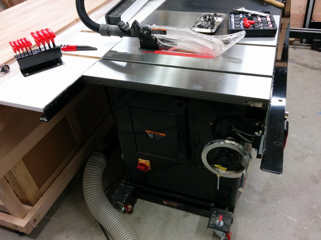
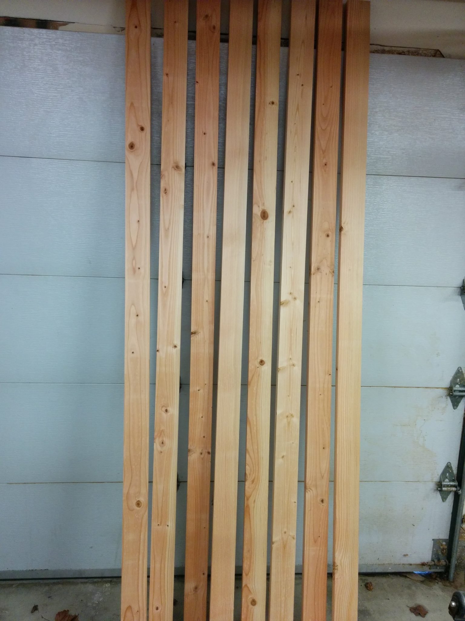
This is a continuation of my other table saw enhancements, Attaching a Sliding Crosscut Table Without Cutting Down the Rails and Attaching an Extra Cast-Iron Extension Wing.

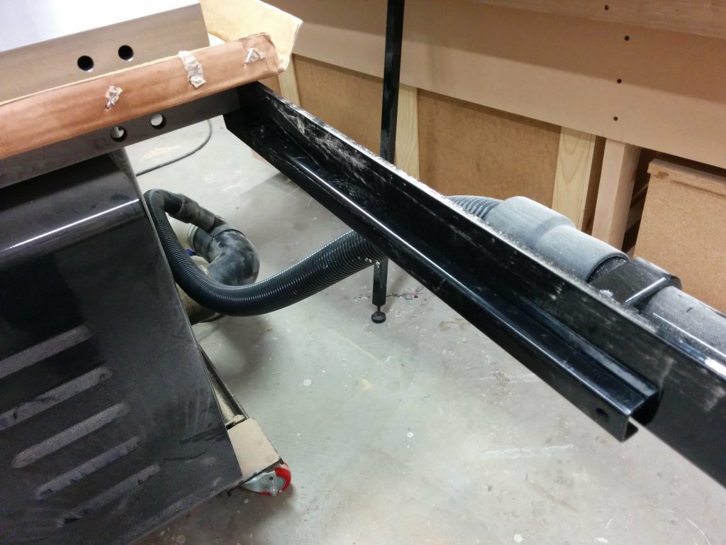
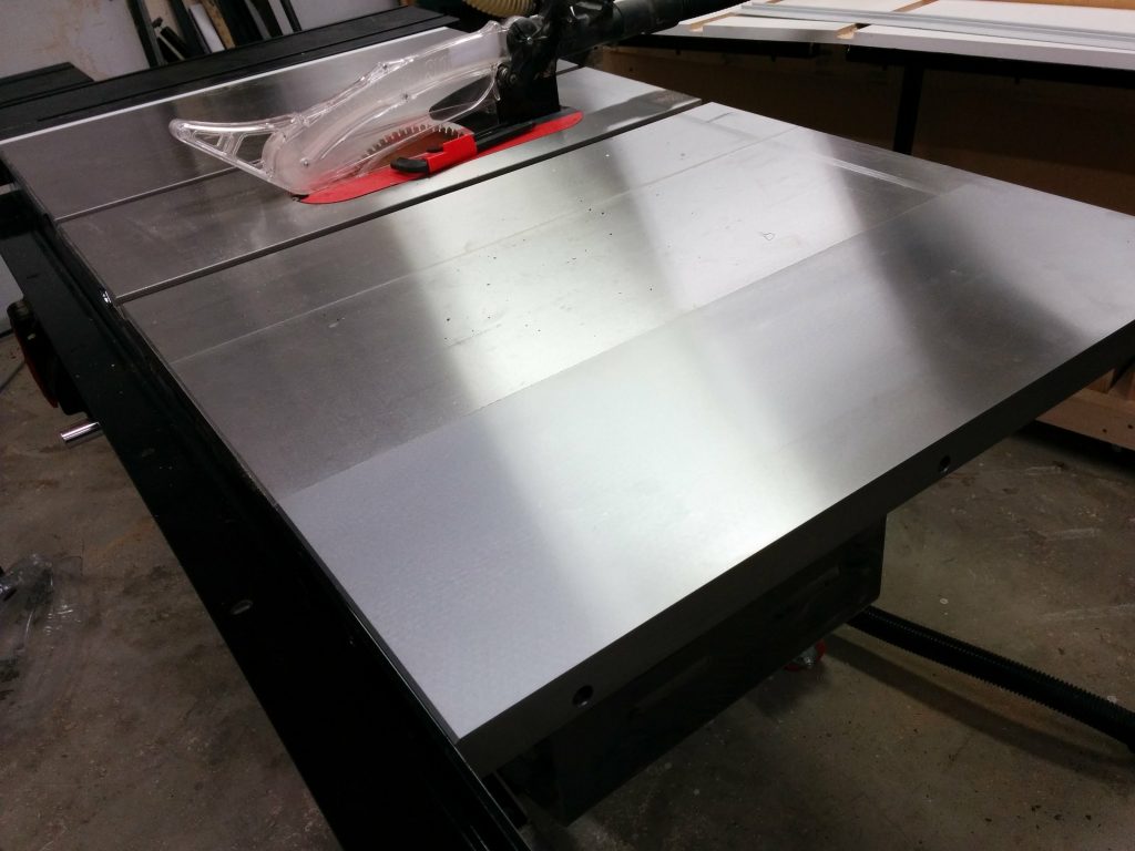
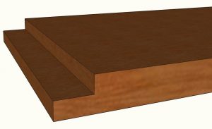
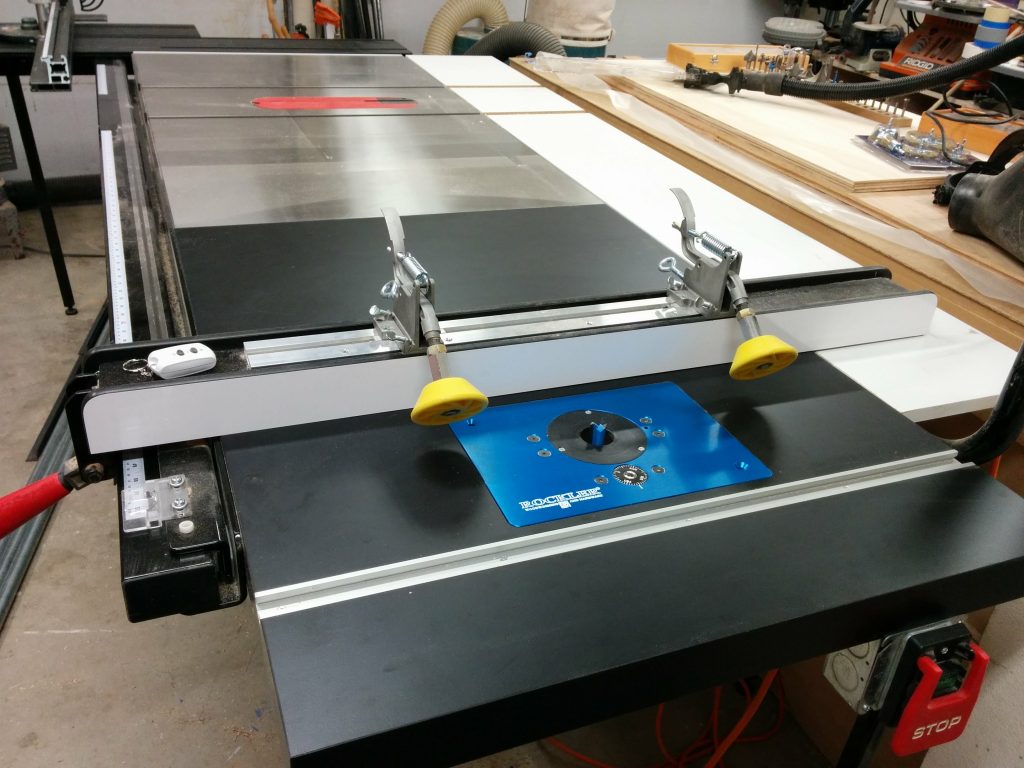
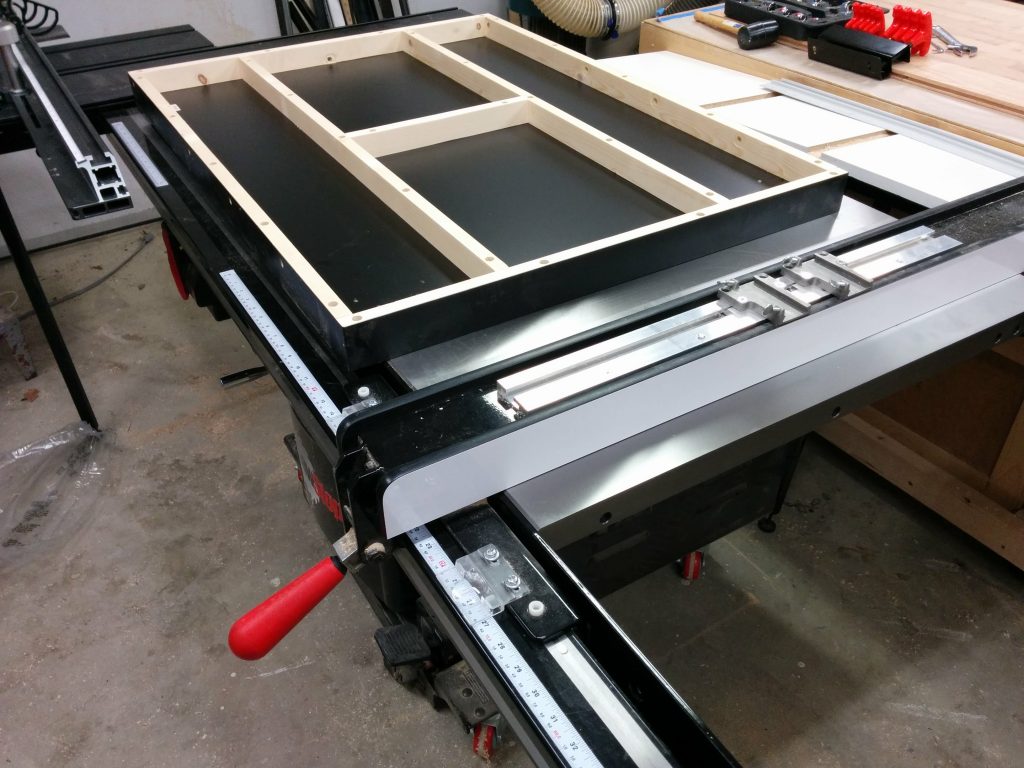
The additional cast iron wing that I attached to my table saw moved the wooden extension table another 10″ past the end of my rails. This allows me to relocate my router table to the far-right edge of the table saw without having to cut notches in my front and rear rails to accommodate the miter slot.

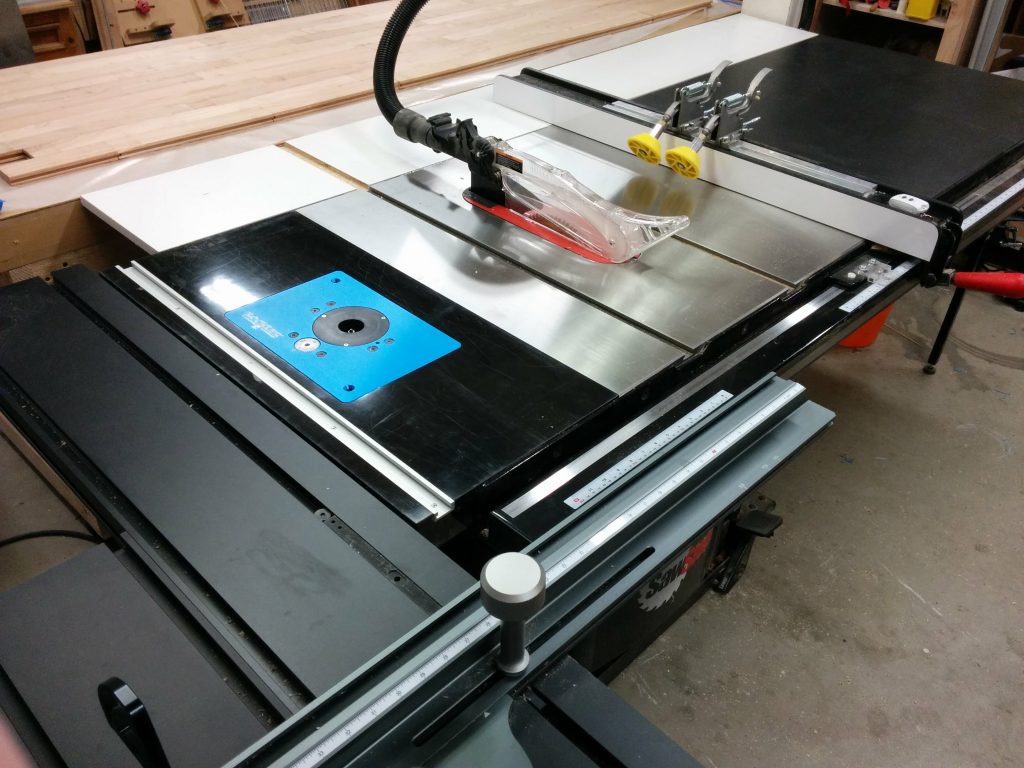
Converting the extension table into a router table.

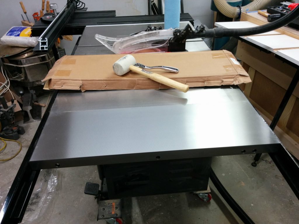
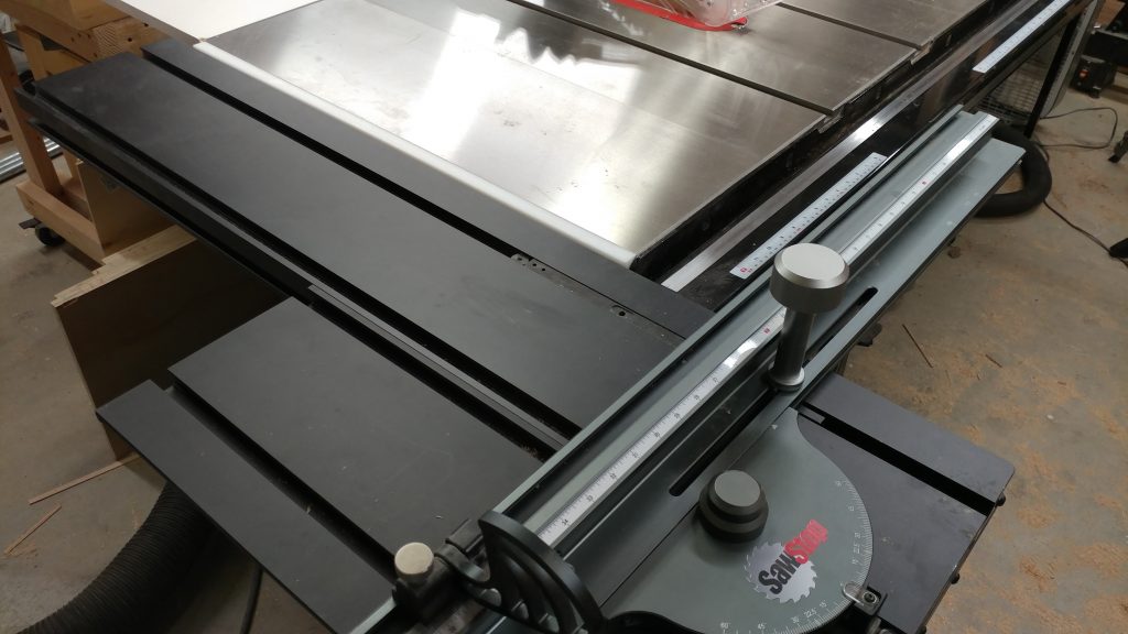
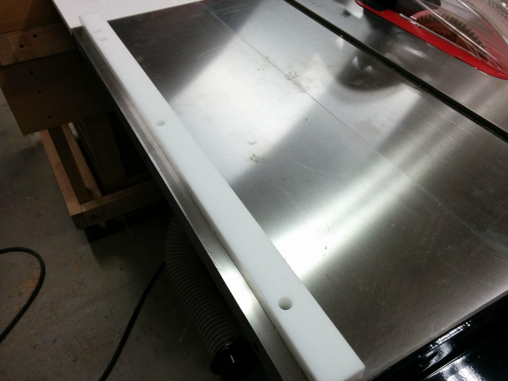
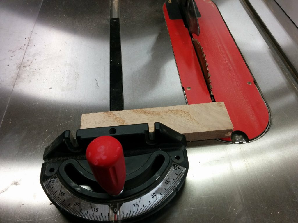
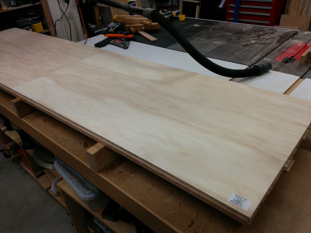
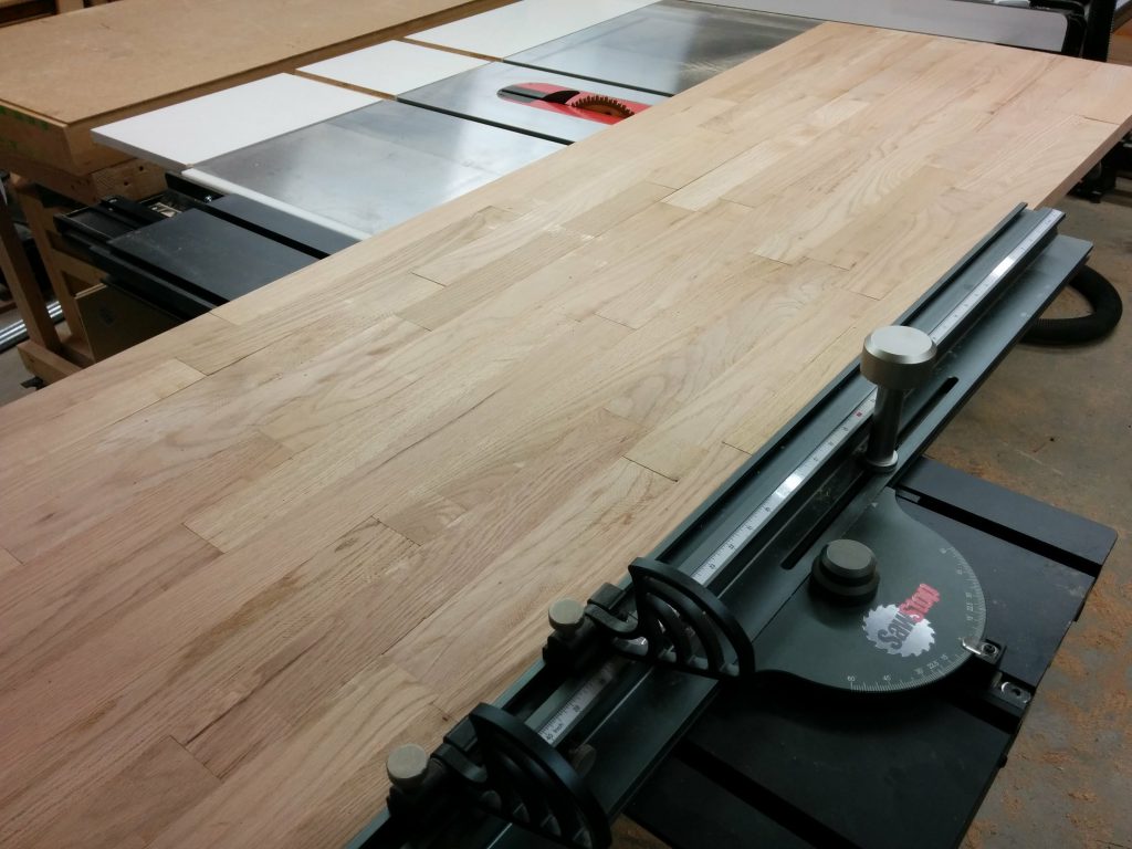
I had to remove my fence in order to attach the additional cast iron wing. I didn’t want to put my fence back on yet but I realized that I needed to so I can cut a dado in the wooden extension table for the miter slot.  This is the same extension table that I had previously removed.  I temporarily reattached the front rail and did a quick fence alignment so my cut would be parallel with the edge of the table.  This led to a slight problem as you’ll soon see.

Temporarily reattached the front tube so I can use the fence to cut a dado in the extension table.

I wanted to make sure I didn’t accidentally cut through any screws so I removed the legs for the table.

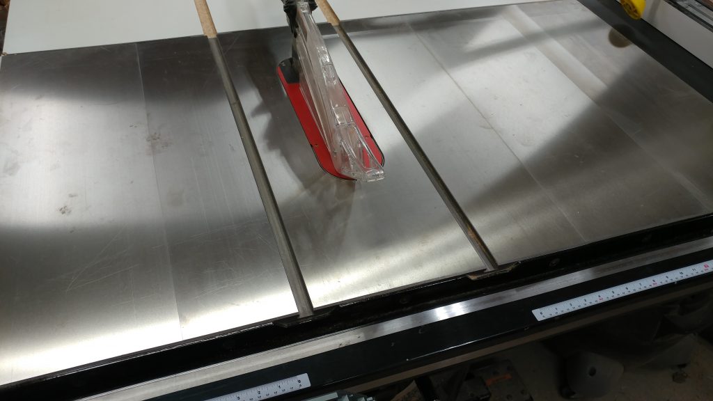
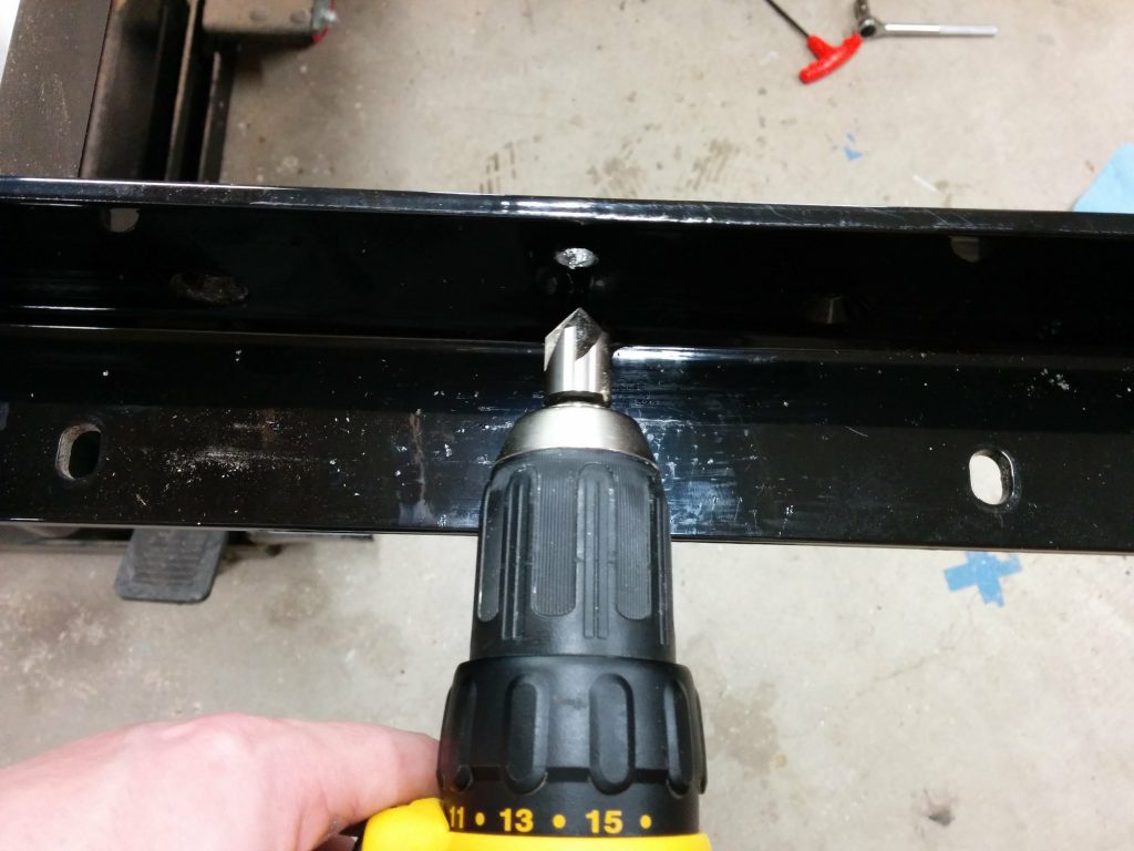
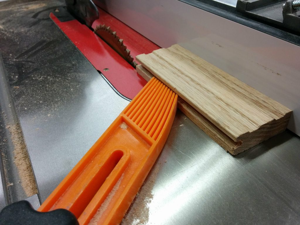
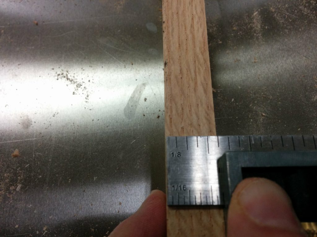
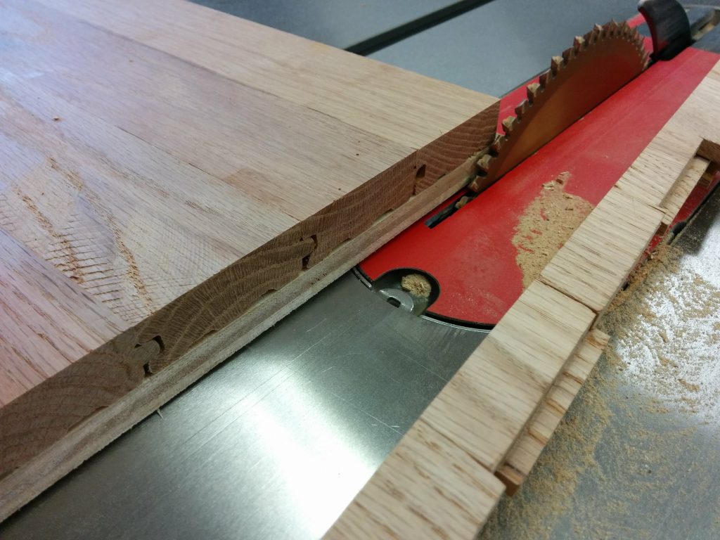
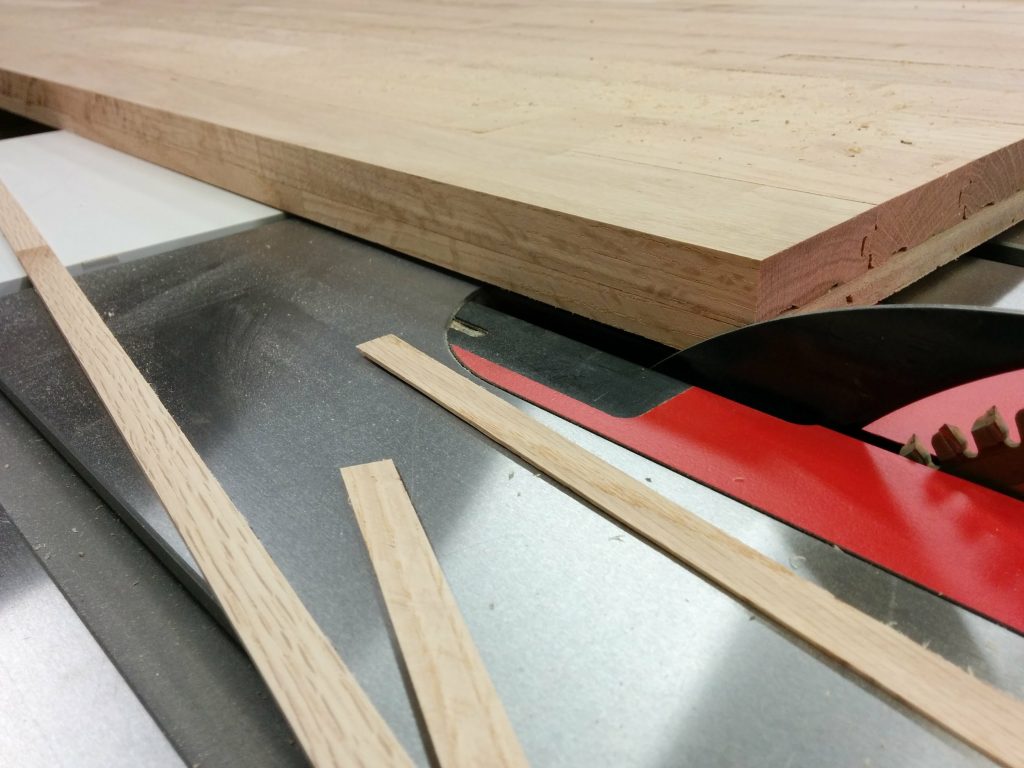
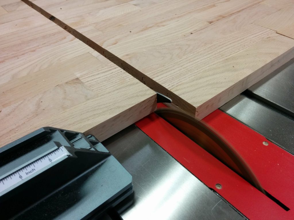
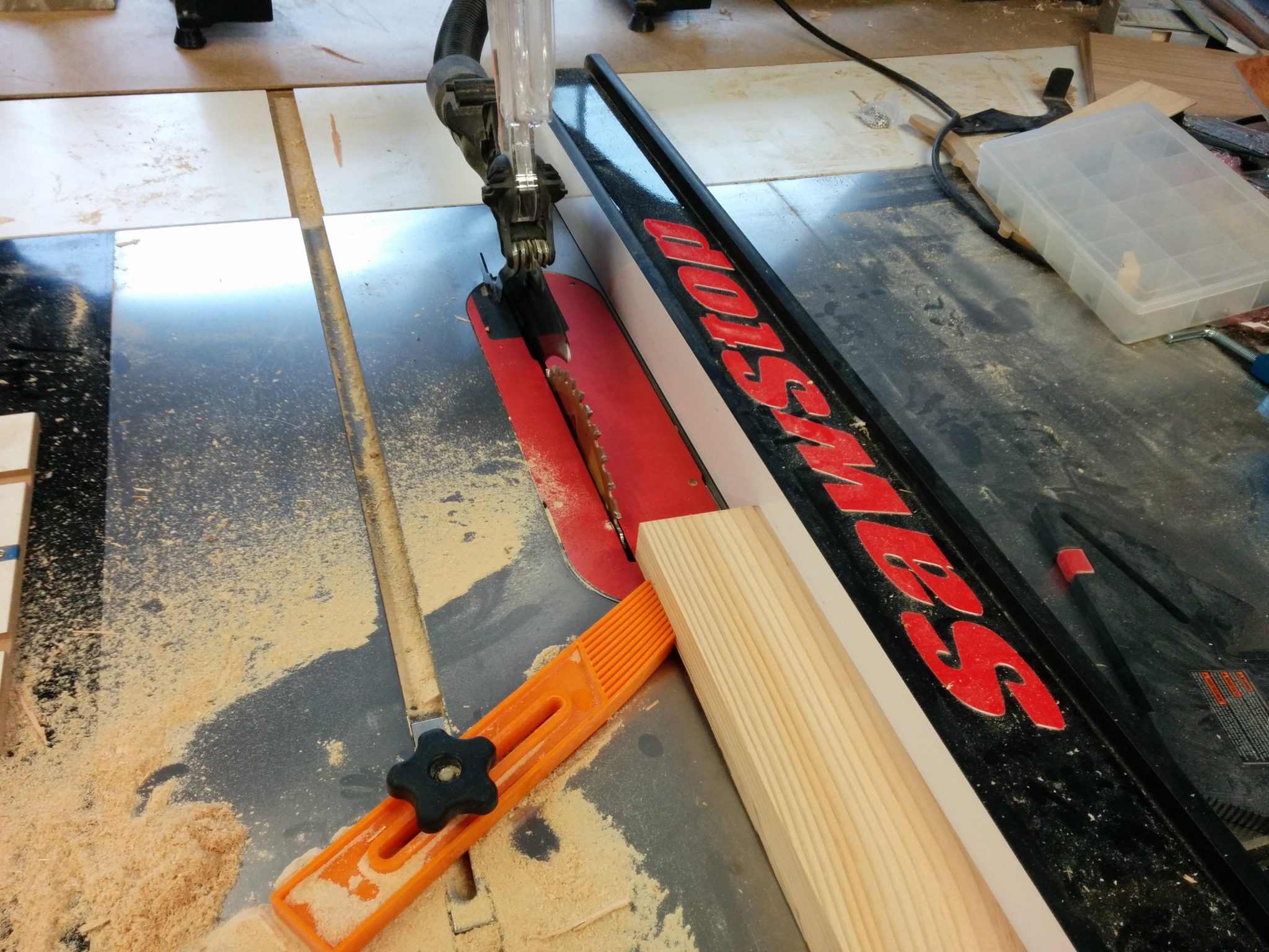
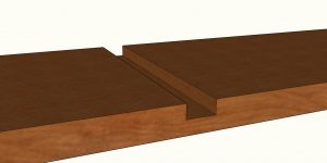
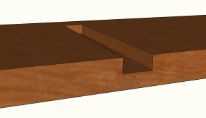
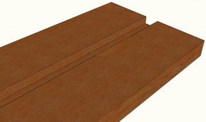
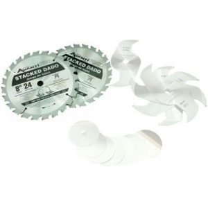
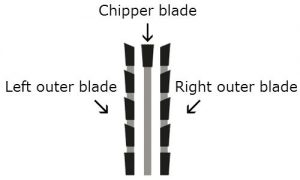
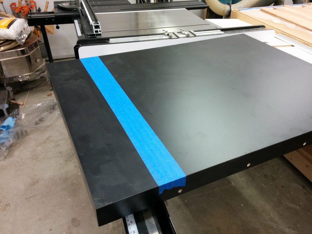
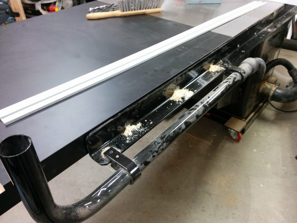
I figured that I would make the miter track 6″ from the edge of the table.  This would ensure that I didn’t hit any screws while cutting the dado.  I wasn’t worried about hitting a screw and activating the brake in the SawStop since a screw by itself is too small to activate the safety system.  I mainly didn’t want to mess up the carbides on my dado stack.  I positioned the fence at the 6″ mark.

Positioning the fence.

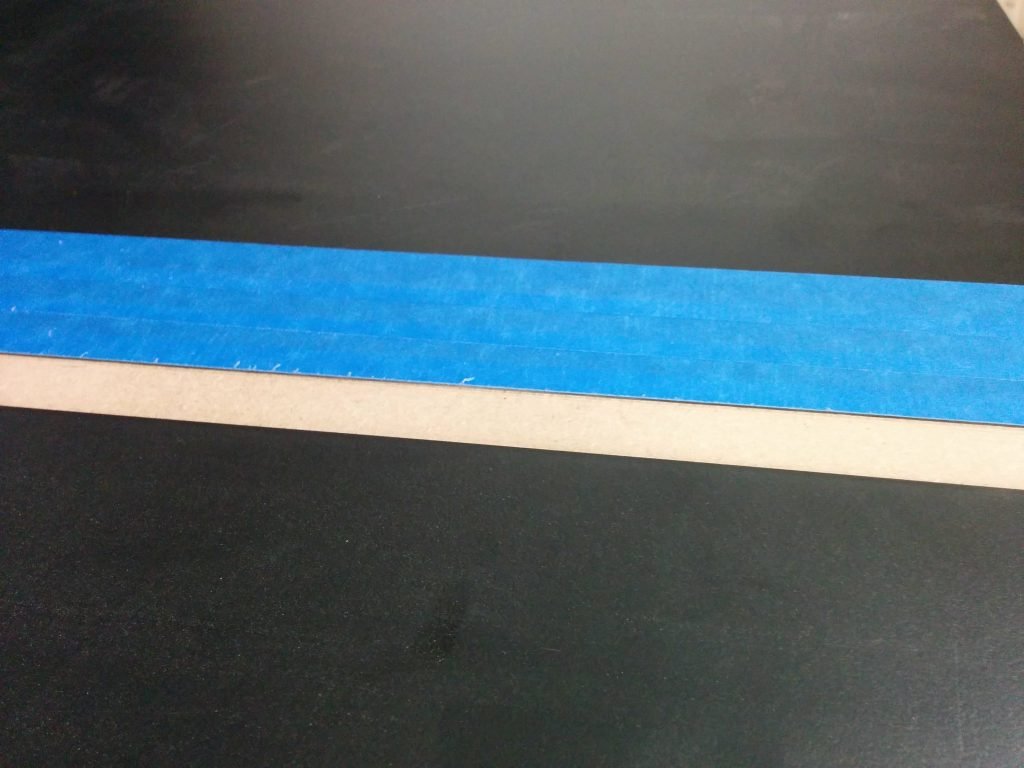
I applied some blue painters tape to help prevent chipping and scratching the laminate on the edges of the dado.  In keeping with tradition, I miscalculated where I should put the tape.  You’ll see what I mean in a second.

Taping where I'll be cutting.
Taping where I’ll be cutting.

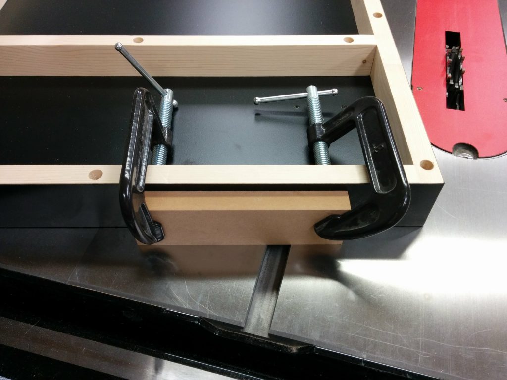
I clamped some scrap wood on the side of the table to help prevent tear-out.  I made sure the clamps were positioned where they wouldn’t get hit by the blades.

Clamping some scrap wood to help prevent tearout.

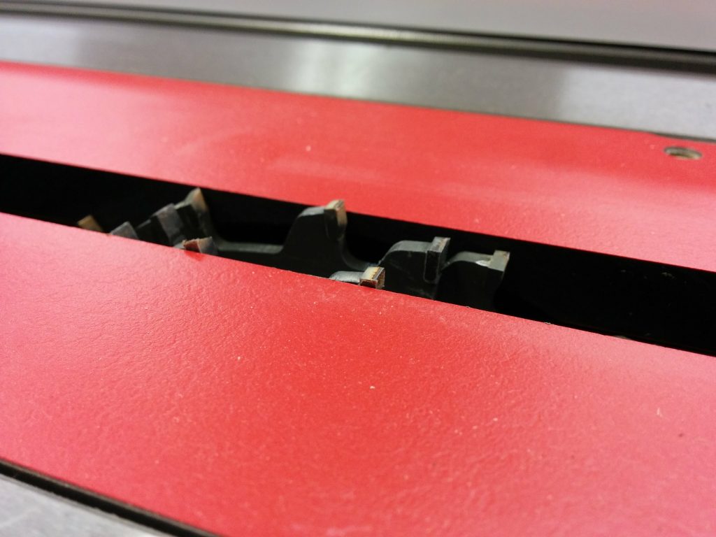
I lowered the dado stack so it would make a scoring cut first.  This is another step that can really help prevent the edge of the laminate from chipping.

Lowering the dado stack so it''ll just cut through the laminate.
Lowering the dado stack so it”ll just cut through the laminate.

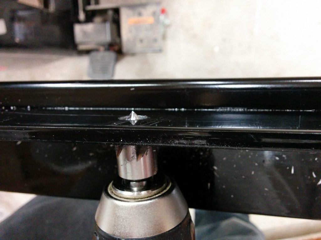
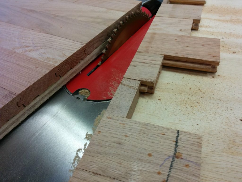
I made my first pass.  As you can see, the blue tape wasn’t positioned correctly so my first cut didn’t have tape on each edge.  As it turns out this wasn’t a big deal.  The laminate that SawStop recently switched to for use on their extension tables is some high-quality stuff and didn’t tear out at all.  I didn’t have similar luck with the laminate for their older extension tables.

Didn't position the tape correctly but it didn't matter in the end.
Didn’t position the tape correctly but it didn’t matter in the end.

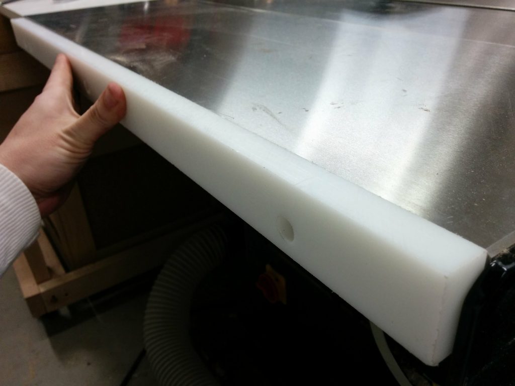
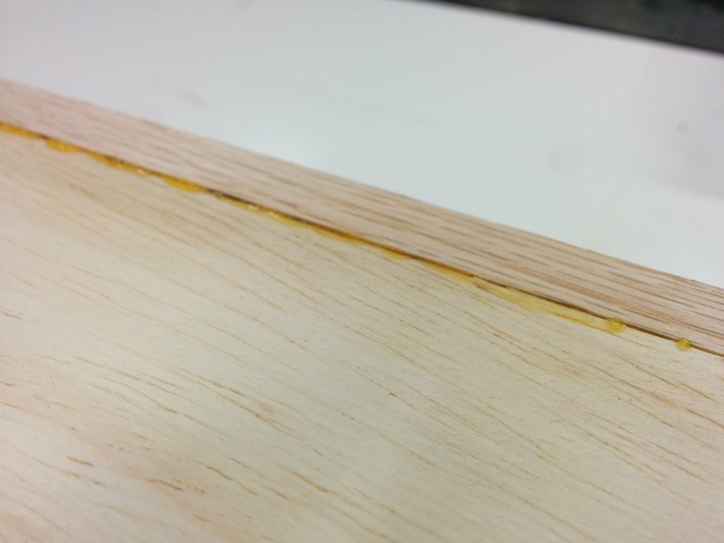
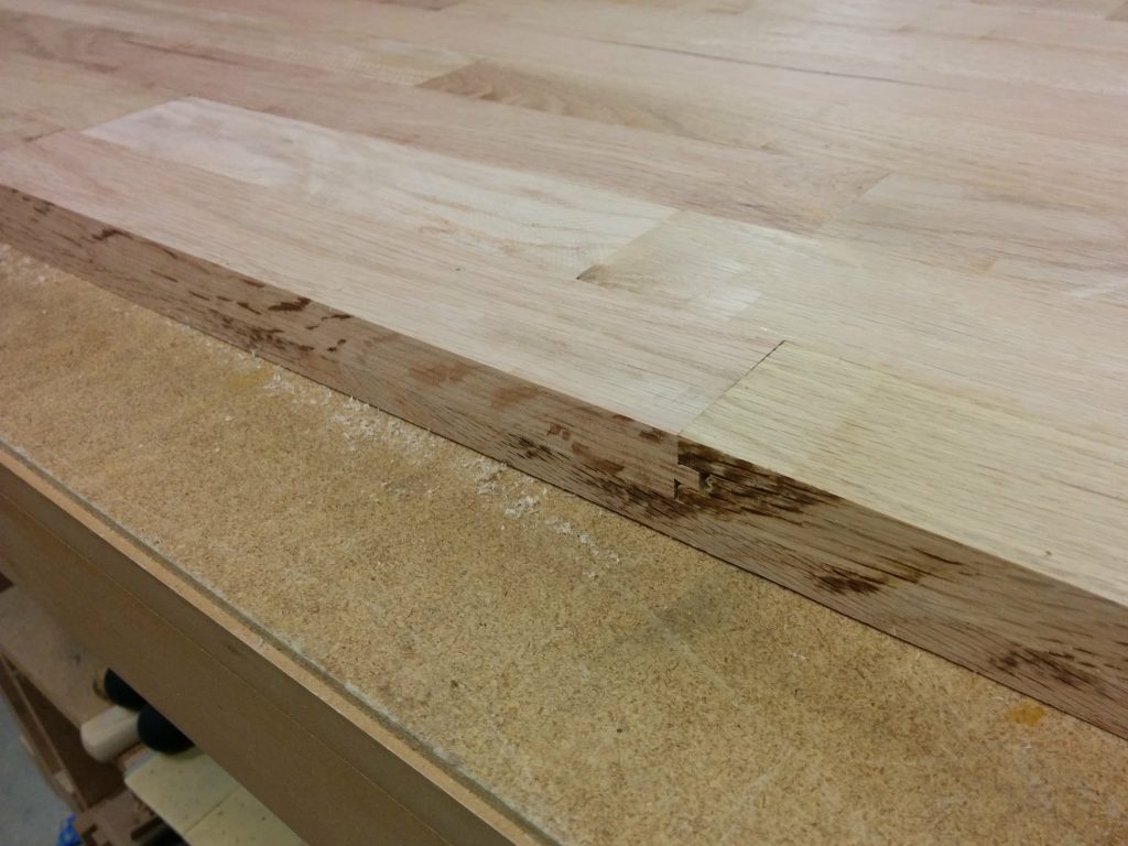
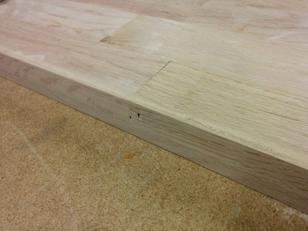
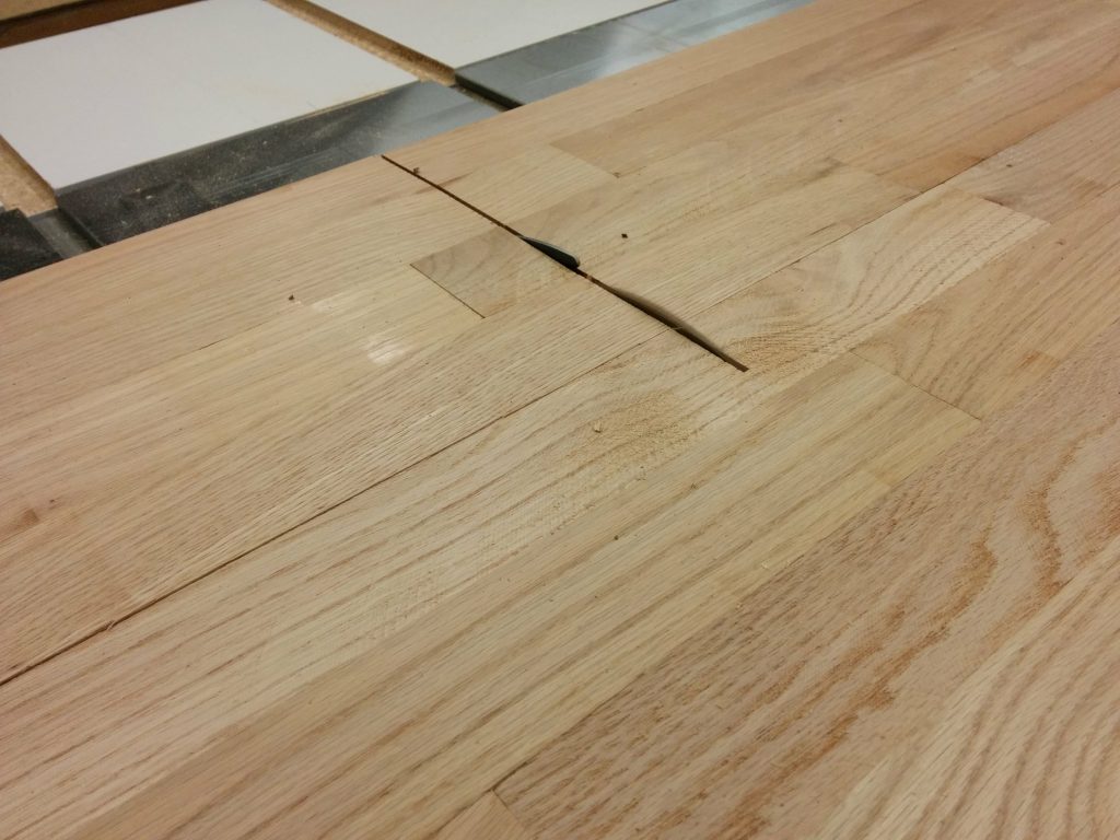
Here you’ll see one of the areas where I screwed up.  Remember when I said I did a “quick fence alignment”?  Well, I should have taken my time.  If I had, I would have noticed that in aligning my fence I also slightly loosened the clamping pressure of the fence on the front tube.  This caused my fence to slide a little bit as I was cutting and caused a slight unevenness in the dado.

Fence shifted while making this cut.

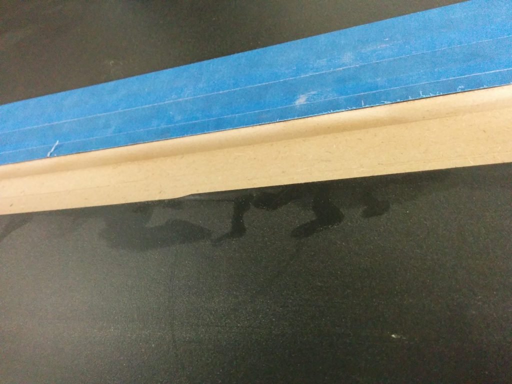
As you can see, the scrap wood kept the laminate from chipping on the edge.

No tear-out!
No tear-out!

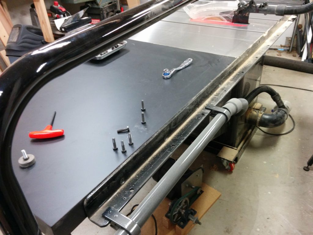
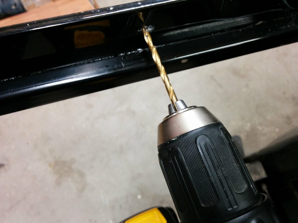
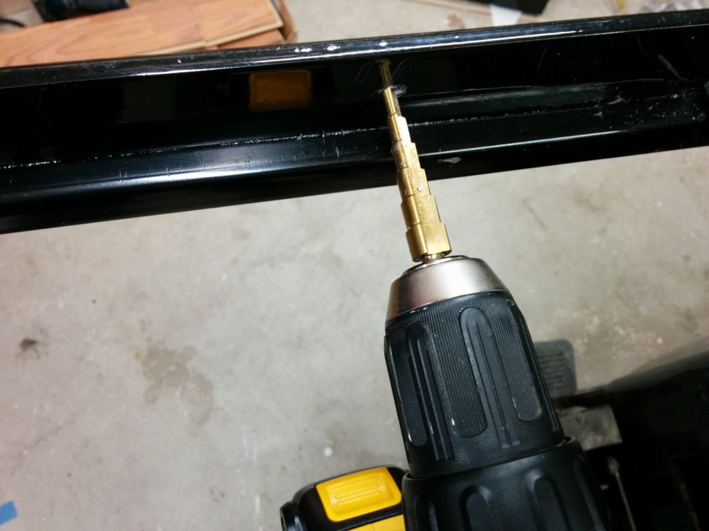
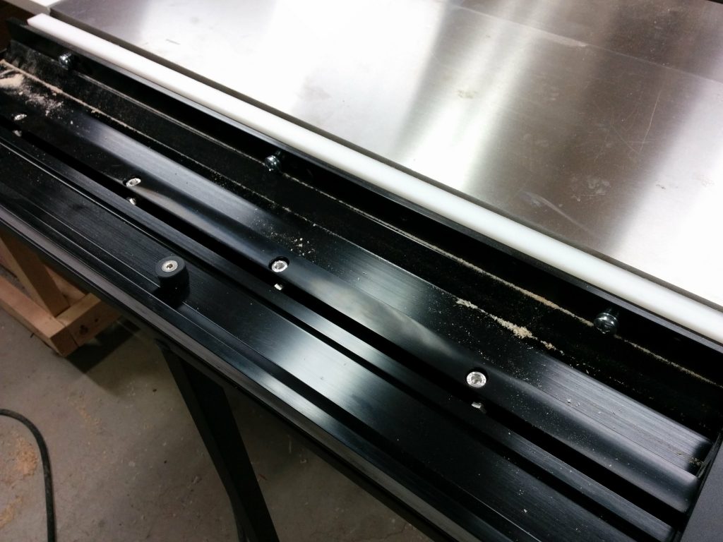
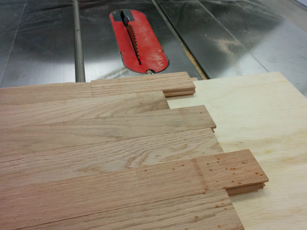
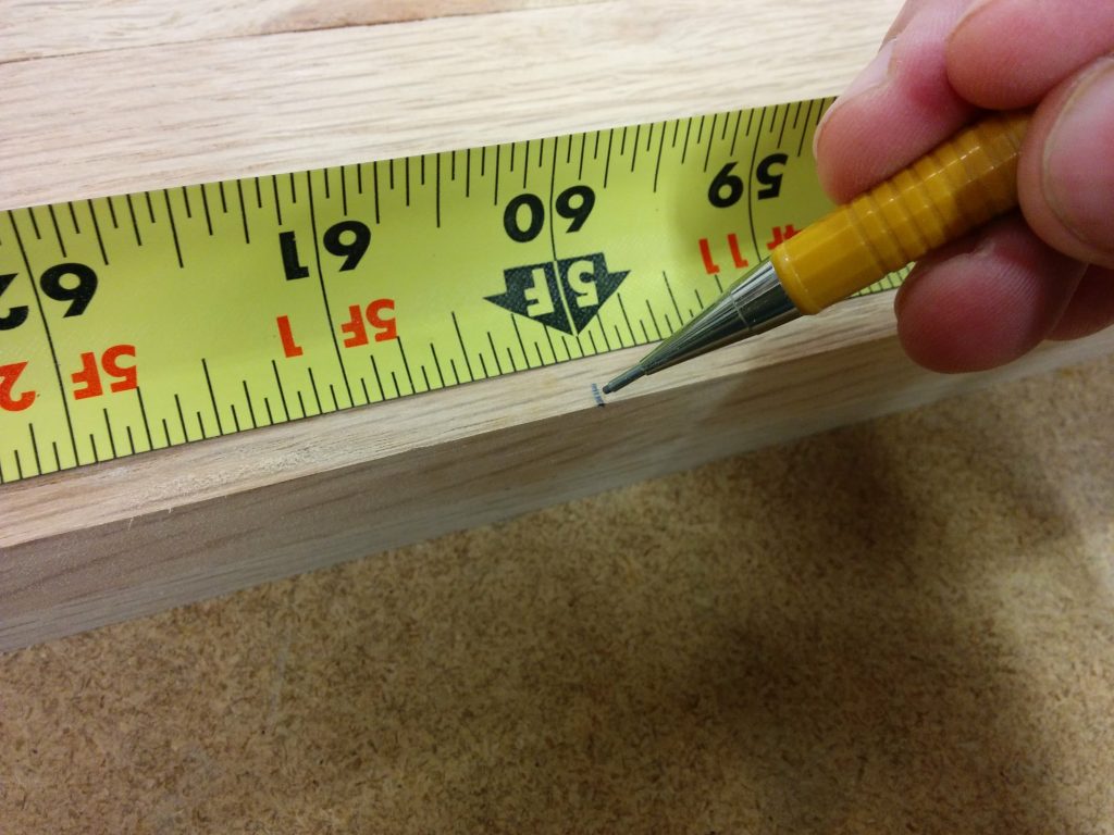
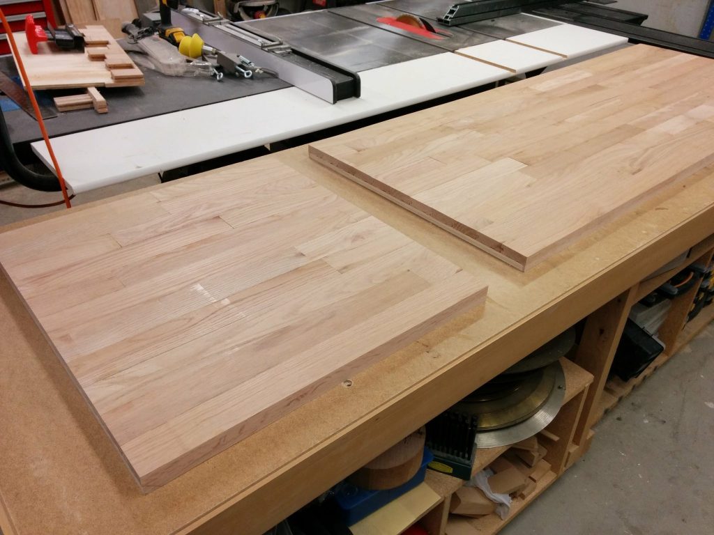
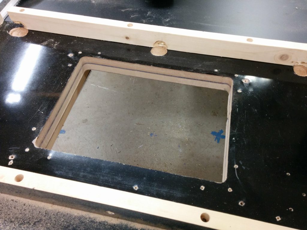
I reattached the legs and temporarily clamped the extension table to the rails and the right wing, making sure it was flush. Then I drilled new holes through the sides of the wooden extension table for the bolts to attach it to the rails.

Lined up the table and drilled holes for the mounting bolts.

I then did the same thing on the back. After the holes were drilled, I reattached the table to the rails using the appropriate bolts, washers, and nuts.

Drilled the mounting holes on the back of the extension table.

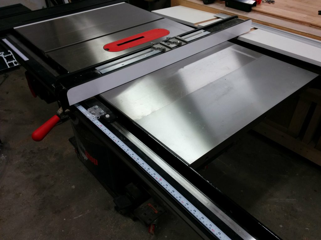
I then reattached my outfeed table to the rear rail.

Reattached my outfeed table.

Now it’s time to mark the opening that I’ll be removing. I’m going to remove most of it with my jigsaw then clean up the rest with my trim router and a pattern bit.

Using the old router table as a template.

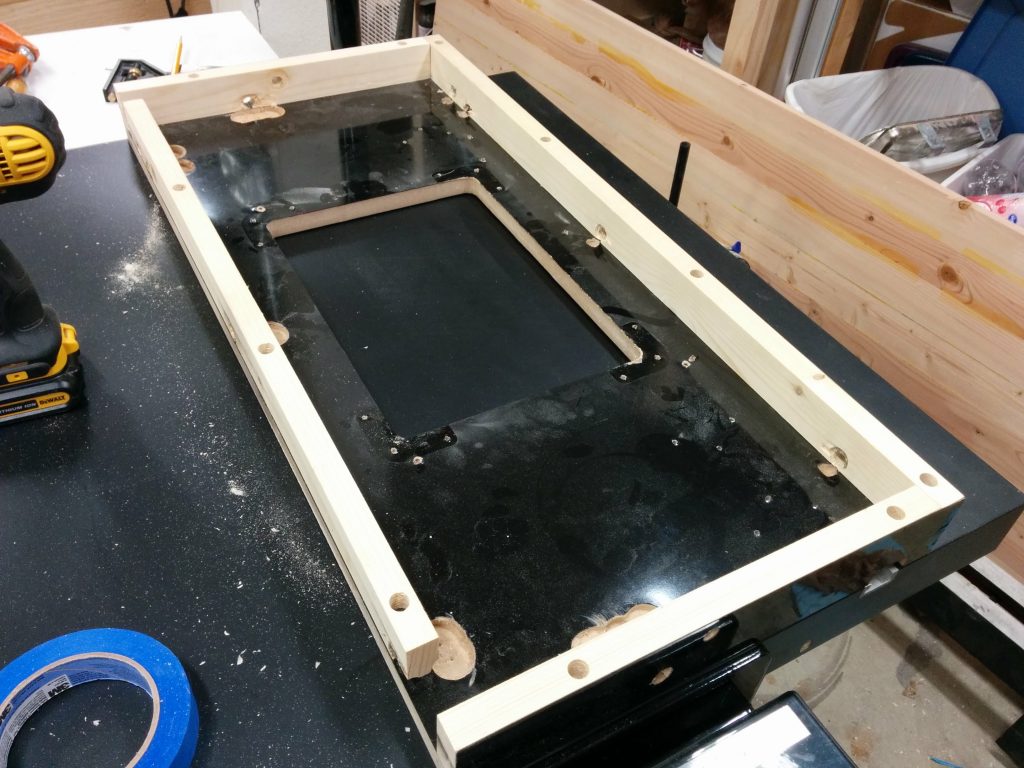
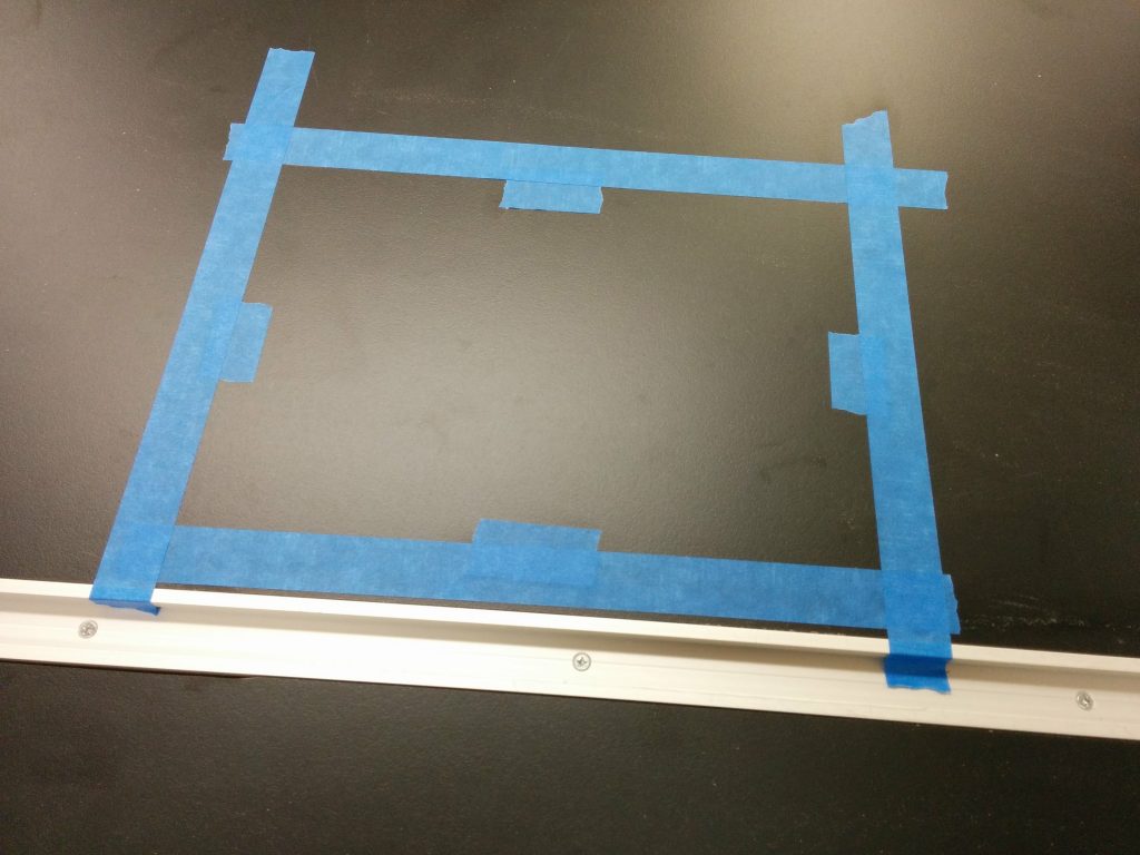
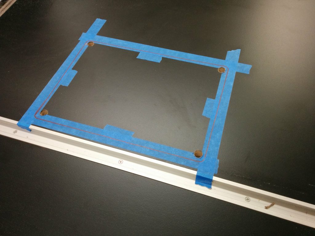
I laid the pattern on the tabletop in the spot where I am going to remove the material. Absolute precision is not critical at this point. I used a few pieces of painters tape to mark the inner edges of the opening.

Temporarily marking the inner edges of the template.

I then took the template off and ran some strips of painters tape over where the edges will be. The actual edges should be somewhat centered in the strips of tape.

Applied blue painters tape over the edges where I will cut out the insert opening.

Then I put the template back in place. Again, absolute precision isn’t critical at this point.

Set the template in place.

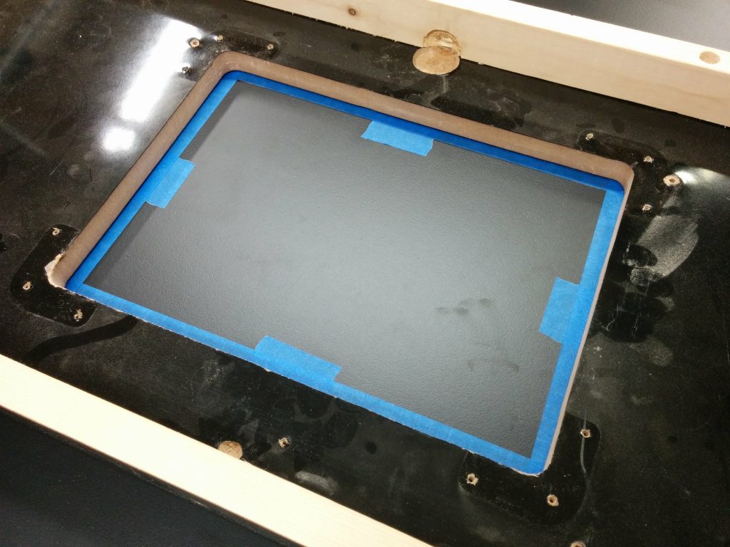
I used a red Sharpie to trace the opening on the blue painters tape.

Traced the outline of the opening with a red Sharpie.

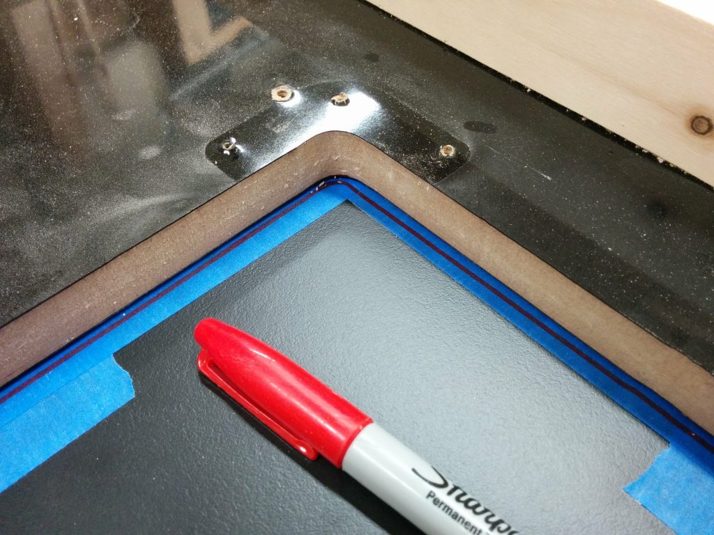
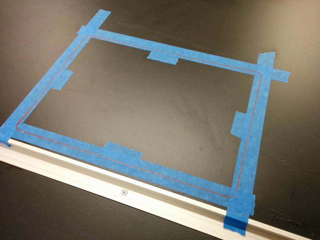
I then removed the template yet again so I can see the outline I just traced.

Removed the template after tracing the outline.

I drilled 1/2″ holes near the inner corners.

The holes have been drilled.

I’m using a jigsaw to remove the bulk of the material, roughly cutting it out about 1/4″ inside the lines.

I'm going to rough-cut out the opening with a jigsaw.
I’m going to rough-cut out the opening with a jigsaw.

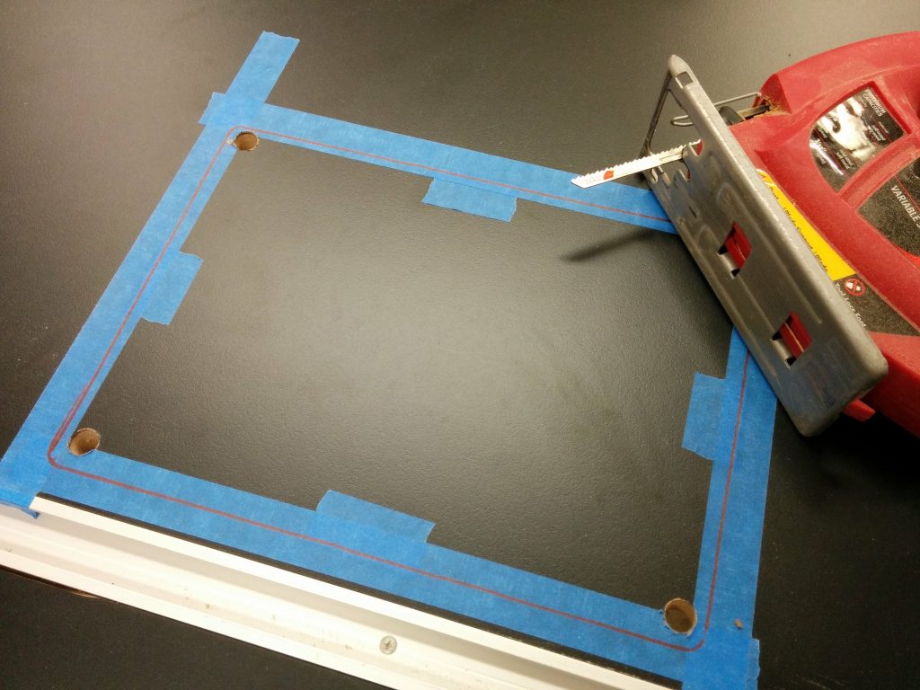
Nice and sloppy. The critical thing is not crossing over the line.

The piece has been removed.

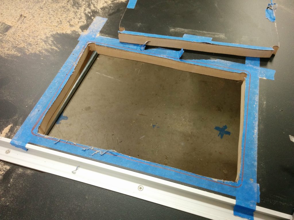
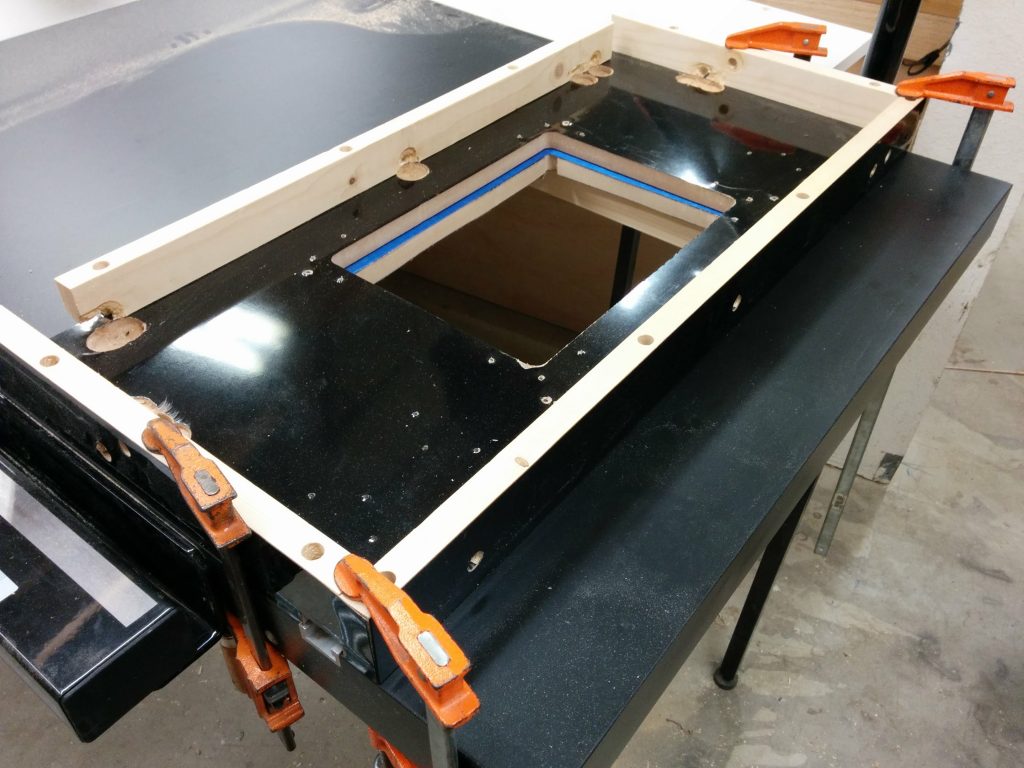
I reapplied the painters tape since it got a bit chewed up then laid out the template. This time positioning is critical so I took my time. I got one end clamped down…

Carefully positioned the left edge of the template and clamped that side in place.

…then used a try square to make sure the template was square with the table.

Using a try square to ensure the template is square with the table.

Once I was satisfied that it was square, I clamped down the opposite end then applied one more clamp to each edge just for good measure.

Carefully clamped the other end in place and secured with additional clamps.

I outfitted my trim router with a 1/2″ pattern bit.

Positioning the router to cut out the opening.

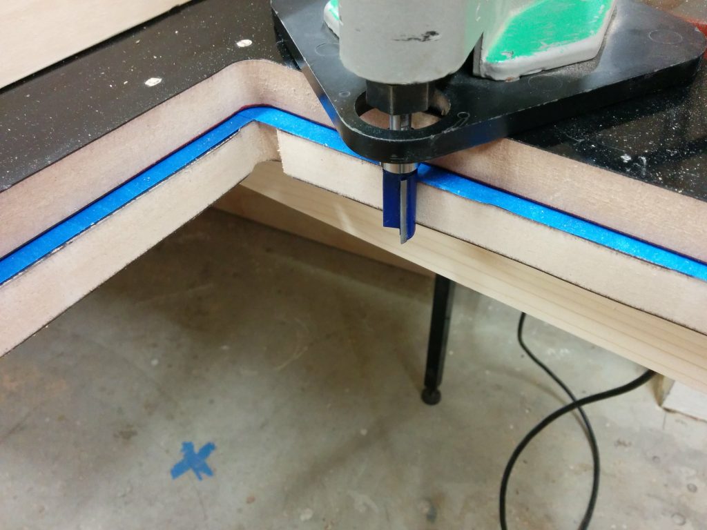
It was throwing up quite a bit of dust so I set up a dust collection hood to grab most of it out of the air.

Getting pretty dusty so I set up my dust shroud.

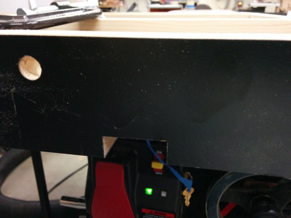
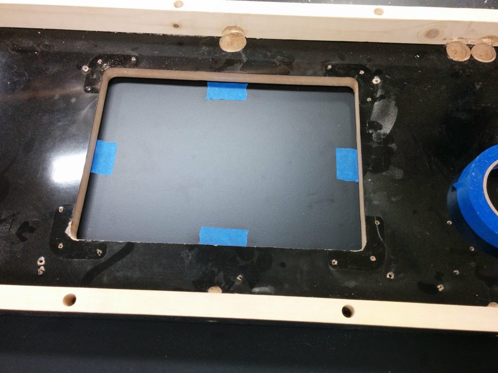
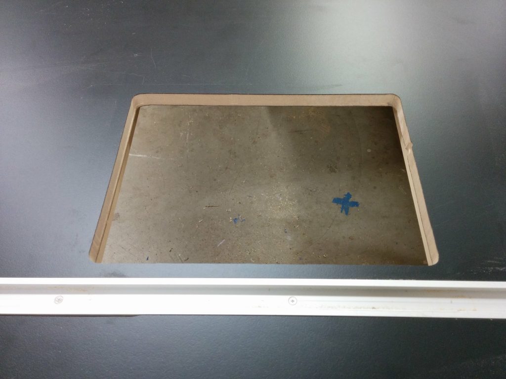
I had a problem with the bearing on this pattern bit coming loose and the whole bit slipping. This caused a little gouge on the inner-right edge of the opening.

Chewed up the opening a bit when the bearing came loose. Otherwise, it looks okay.

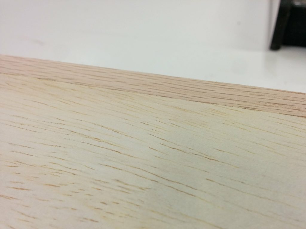
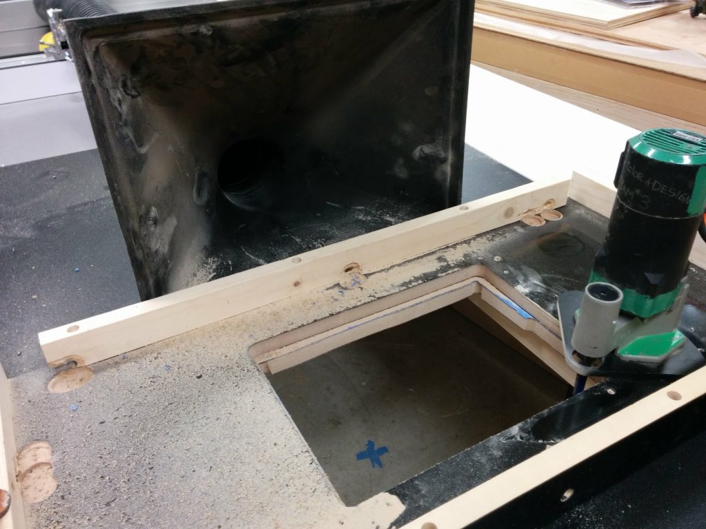
I removed the template and the painters tape so I could inspect the edge. There was a little divot where the bearing came loose but other than that, it wasn’t bad.

Removed the painters tape. Other than the small goober on the right, it didn't turn out bad at all.
Removed the painters tape. Other than the small goober on the right, it didn’t turn out bad at all.

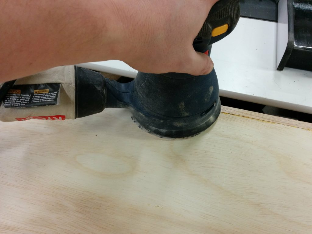
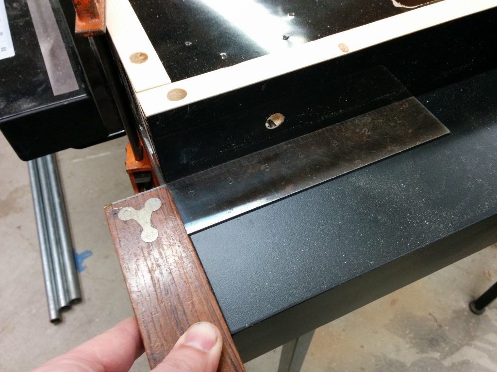
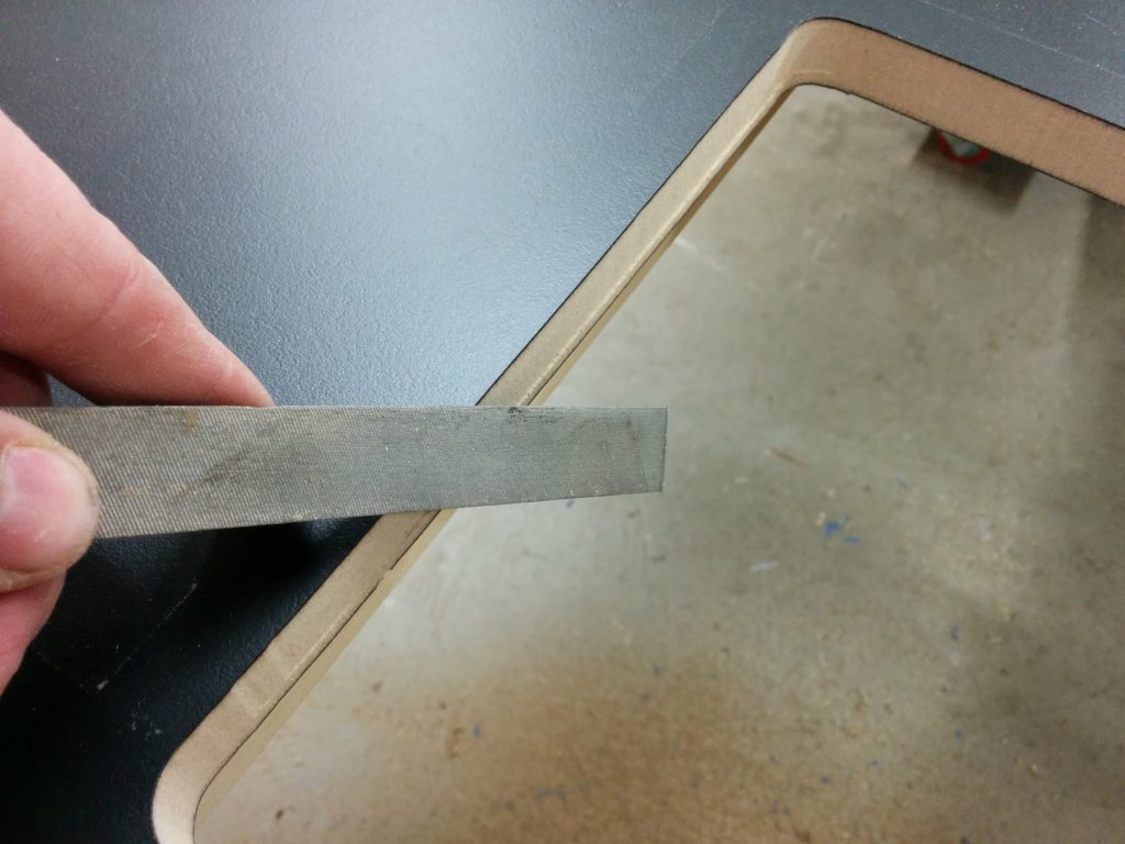
I used a file to break the edge a bit.

Broke the edges a bit with a file.

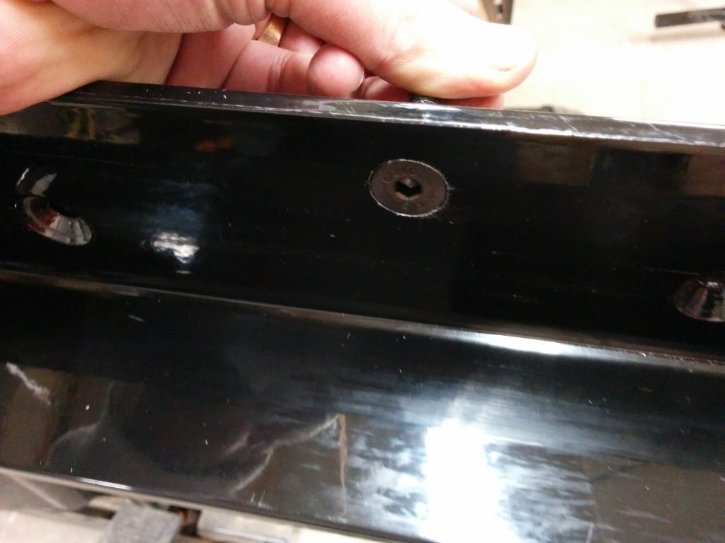
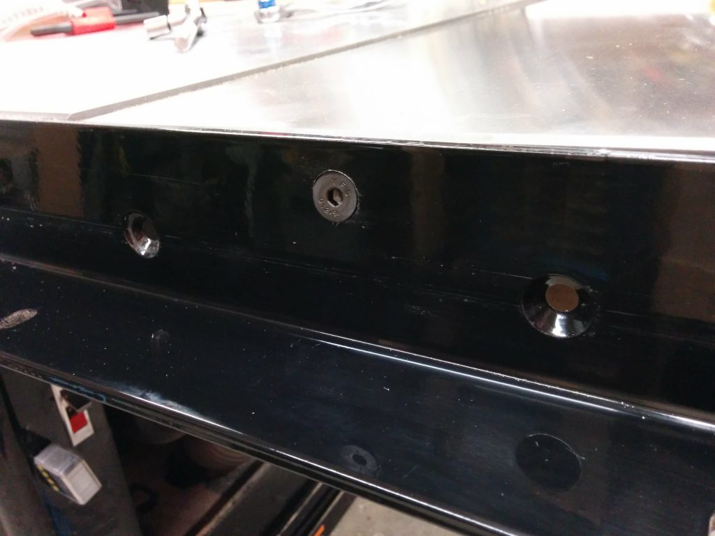
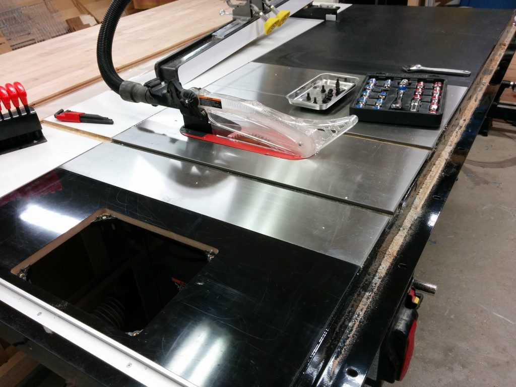
This particular extension table has some support bars underneath. They are only screwed in and are easy to remove.

The table braces are going to get in the way so I'm going to move them.
The table braces are going to get in the way so I’m going to move them.

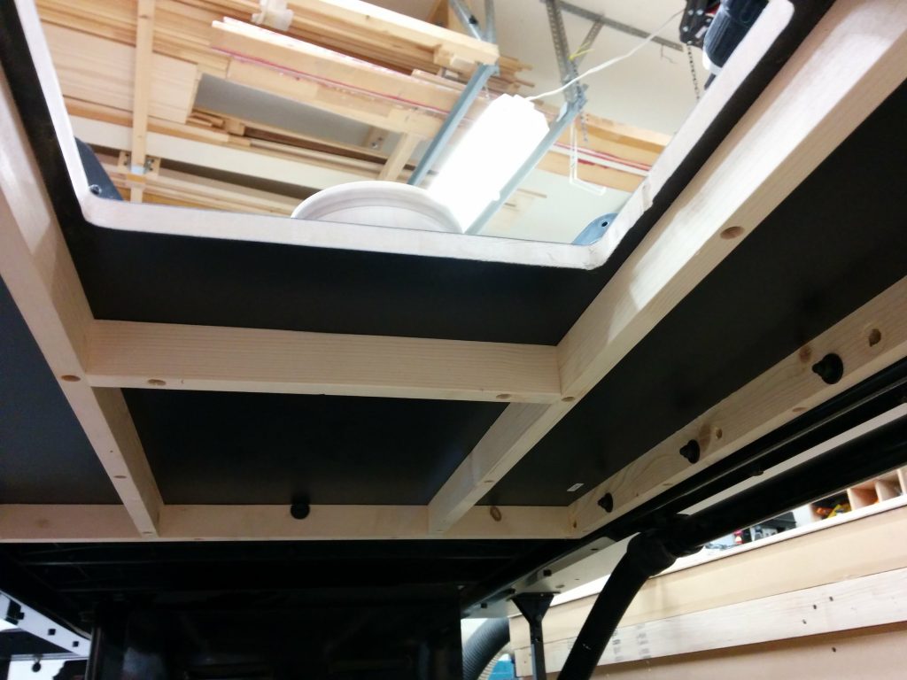
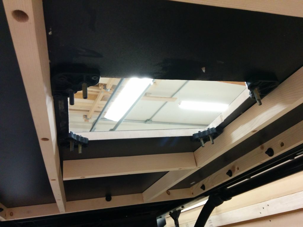
I removed the support bars so I would have room for the Kreg PRS3040 Precision Router Table Insert Plate Levelers which installed easily from underneath the table.

Installed the Kreg PRS3040 Precision Router Table Insert Plate Levelers.

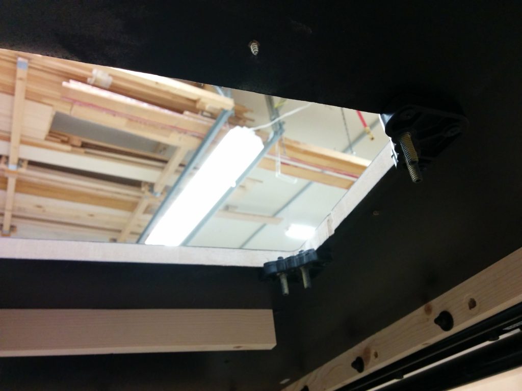
Each leveler has two set screws that are used for leveling the router insert.

The Kreg levelers went in easily.

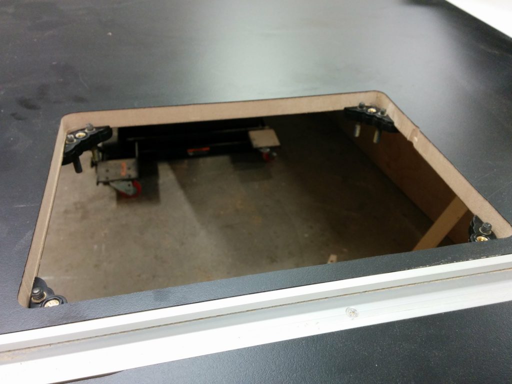
I reinstalled the support bars. I had to move them by about 1/4″ from their usual spot.

I reattached the supports under the table.

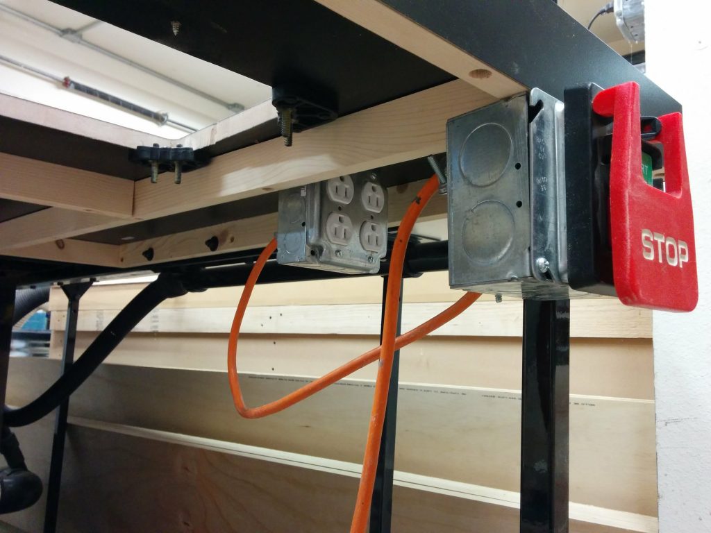
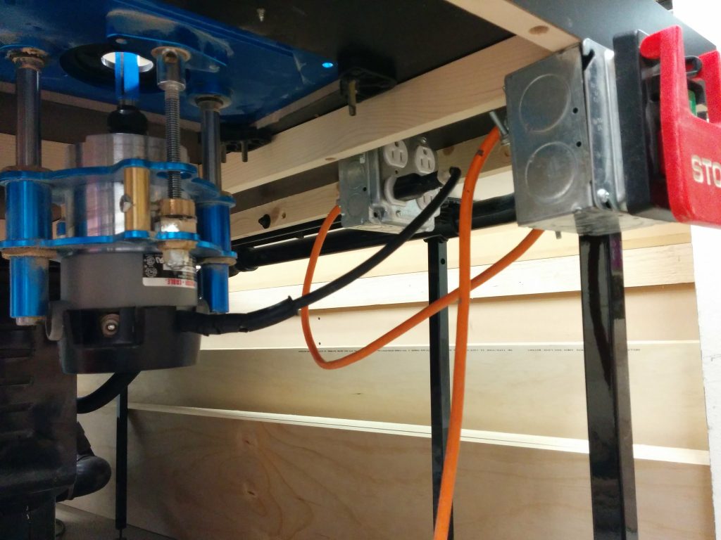
The next step was to start hooking things up. I installed a 4-outlet electical box that was wired to a motor power switch.

I hooked up an electrical outlet and a knee switch under the table.

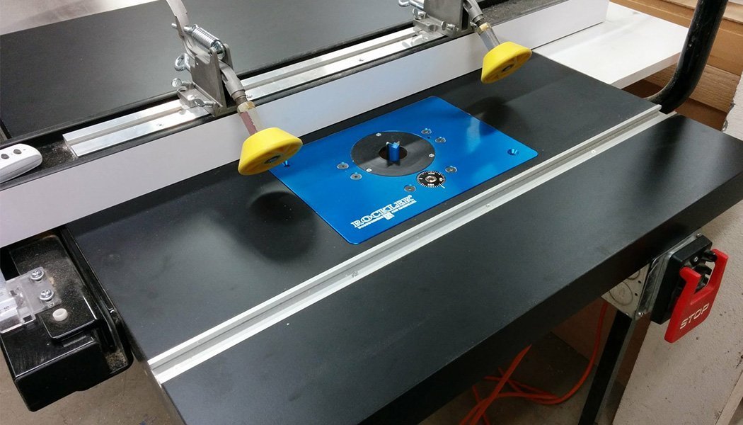
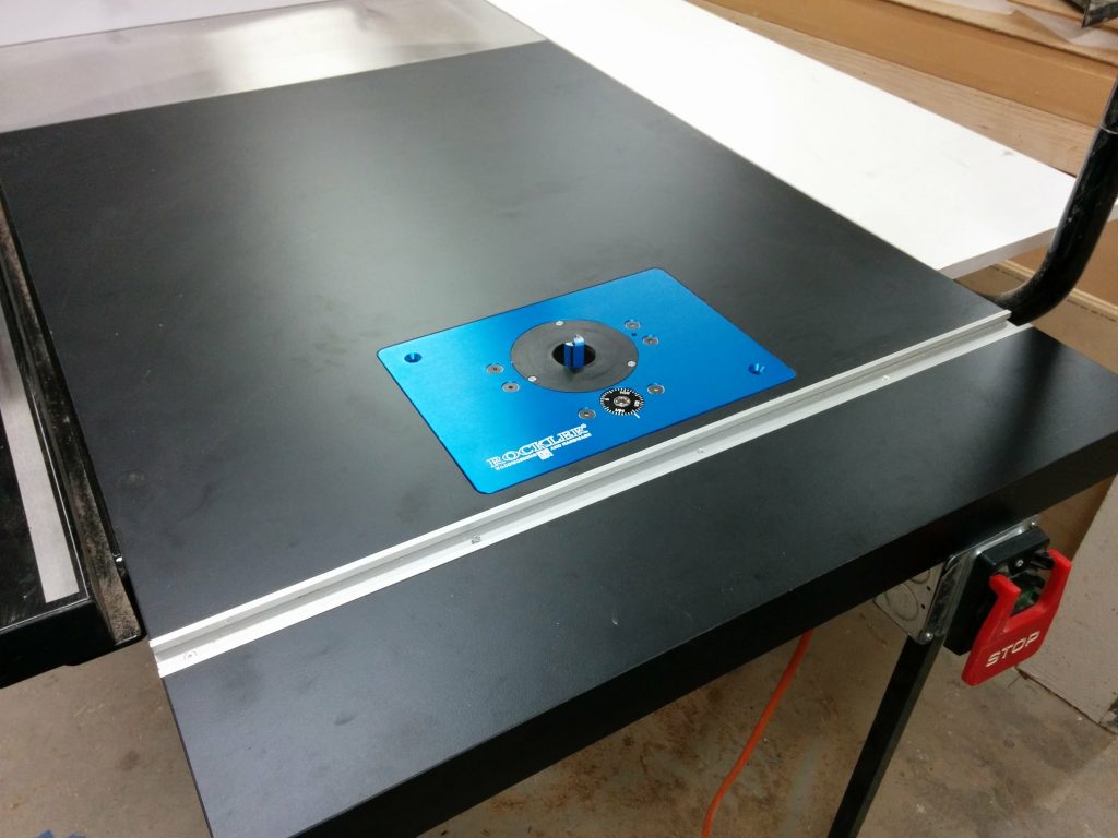
Then it was simply a matter of dropping the Rockler router lift in place and plugging in the router.

The router lift has been placed in the table and the router plugged into the outlet.

A little bit of leveling and I’m all done.

The router table is all finished.

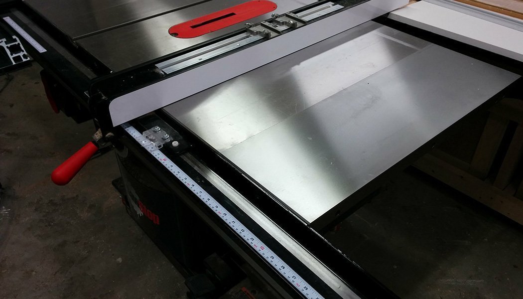
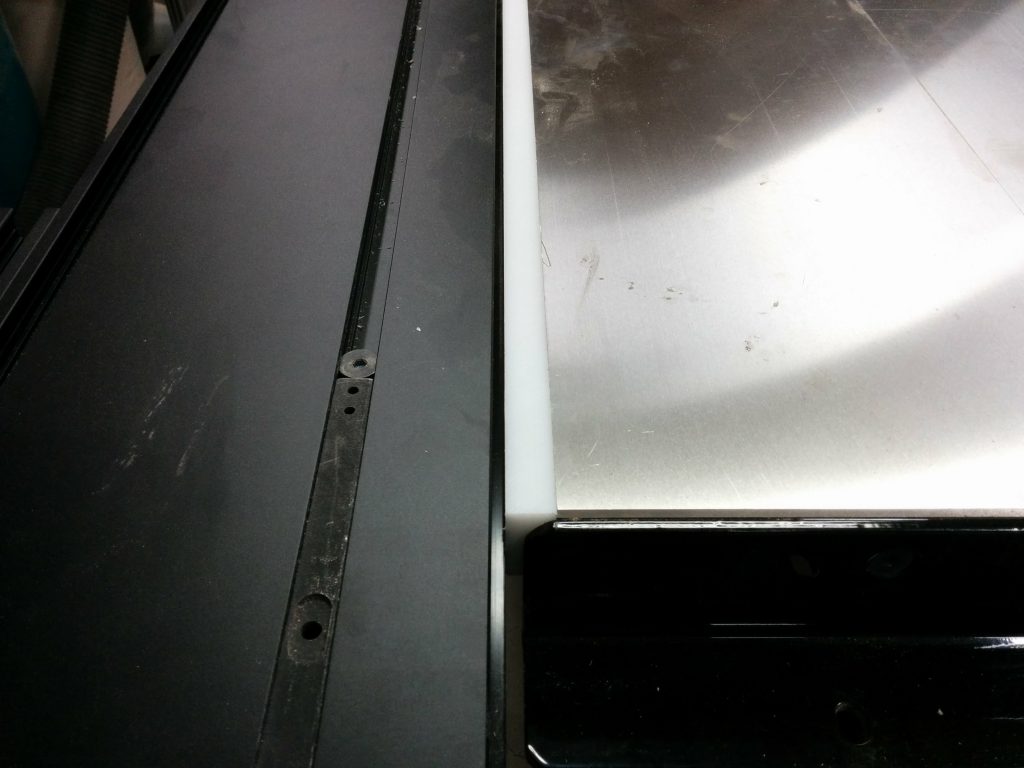
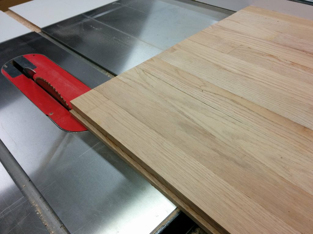
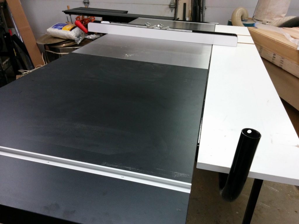
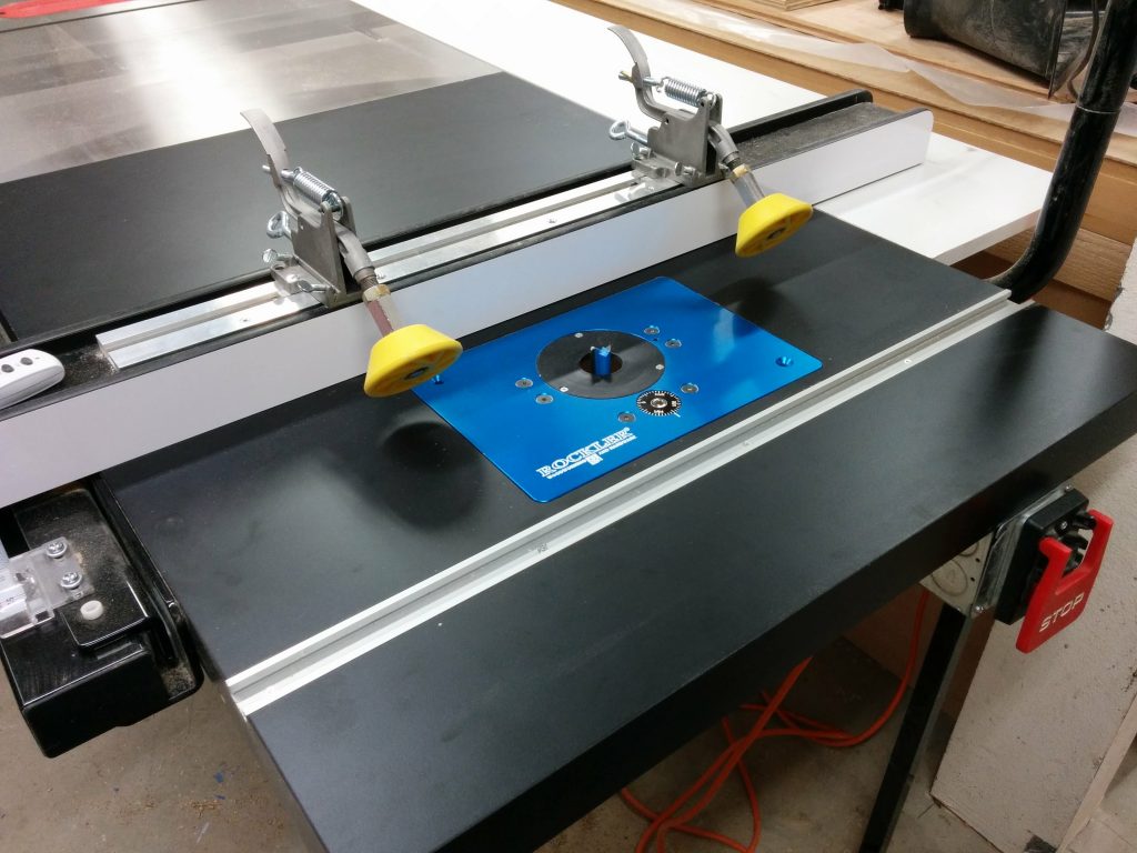
I can use the table saw fence with the router table. This photo shows how close I can get it to the router bit. I will be making an auxiliary router table fence with built-in dust collection that I can attach to my table saw fence, but that’s a project for another day.

I can use the table saw fence with the router table as well.

That’s it! Up next is an enclosure for the router and maybe some drawers for storing router bits. For now, I’ve got some other projects that require my attention.

If any of this has been helpful to you, or if you have any suggestions or questions, please take a minute to post a comment below. I’d especially like to hear any suggestions for projects that you’d like to see me tackle.

Table Saw Enhancement – Attaching Extra Cast-Iron Extension Wing.

SawStop Industrial Cabinet Saw with an extra cast iron wing.


This is a continuation of Table Saw Enhancement – Attaching Sliding Crosscut Table Without Cutting Down the Rails.

Now that I’d removed my existing router table, I needed to relocate it to the right edge of my table saw. Since I use a miter slot on my router table and I wanted to avoid cutting notches in my front and rear fence rails, I decided to add an additional cast-iron extension wing to the right of my main saw table.

Installing an extra cast iron wing.

I had to remove the wooden extension table in order to attach the new cast-iron wing.  As a result, I needed access to the bolts in the rear rail so I took off my outfeed table.  This is giving me a good opportunity to clean some neglected areas of my saw as well.

Removed the outfeed table so I could access the rear bolts.

I then removed my wooden extension table.

Removed the wooden extension table.

I used some magnetic tool holders and attached them to the inside of the front and rear rails.  These will help hold up the cast iron extension wing while I get it bolted to the table.

Magnetic tool holders help to support the new cast-iron wing.

I temporarily attached the new wing to the existing wing using three bolts along with washers and lock nuts.  I was very careful to get the seam between the two cast iron wings nice and flush.  There wasn’t anything holding the new wing to the front and rear rails yet.  That was my next step.  I marked the holes in the new wing on the inside of the rails using a silver Sharpie.  Then I took this new wing back off.

Temporarily attaching the new wing to the existing wing.

I used a small drill bit (somewhere in the neighborhood of 1/8″ in diameter) to drill a starter hole.  You will want to take your time and use plenty of cutting oil when drilling through powder-coated steel.

Drilling the ~1/8" starter hole.
Drilling the ~1/8″ starter hole.

I then moved up to a step bit once the starter hole was drilled.  I believe I drilled this to be 3/8″ in diameter.  Again, take your time.

Expanding the hole with a step bit.

I added a countersink to the front of the hole once the hole was the correct diameter.  The bolts that are used for attaching the cast-iron wing to the rails are countersunk allen bolts.

Adding a countersink to the front of the hole.

This took a long time to do.  The steel on the SawStop rails is pretty tough stuff and I wanted to avoid having the powder-coating start to chip off.

Take your time with this so you don't chip the powder-coating.
Take your time with this so you don’t chip the powder-coating.

It took a while but finally the countersink was deep enough so the bolts didn’t stick out at all.  This is important so they don’t interfere with moving the fence back and forth.

Took a while but I'm done.
Took a while but I’m done.

I loosely  reattached the wing and started tightening up the bolts.  The holes in the cast iron wing are over-sized and not threaded so I had a little bit of wiggle room to help with alignment.

Loosely attaching the bolts.

I got the wing all tightened up and aligned properly.

Tightened and aligned.

The additional cast-iron has been nice to work on. Drilling through the powder-coating wasn’t as bad as I was expecting it to be. I’ll most likely add one or two more cast-iron wings in the future. I know that there is a limit to how much I can add before the saw starts to tip when I try to move it but the sliding crosscut table may help offset the weight of all the cast iron.

If this has been helpful or if you have any questions that I failed to answer, please leave a comment below.

Up next, I’m adding a router table to the right end of my table saw extension table.

Table Saw Enhancement – Attaching Sliding Crosscut Table Without Cutting Down the Rails.

SawStop Sliding Crosscut Table installed without having to cut down the front or rear rails.


My table saw is fairly decked out and I’ve made some modifications to it in the past but some of them weren’t working that well for me.

My saw is a SawStop Industrial Cabinet Saw 3 HP single-phase, 230 VAC machine (ICS31230) with a 52″ fence system and the sliding crosscut table.  As an experiment, I had previously taken the left cast-iron wing off and replaced it with a custom router table.  The reason behind having the router table in that spot is because I didn’t have any room on the far-right edge of the saw the way my shop was set up previously.  I needed to have it on the left but I wasn’t sure if it would work with the sliding crosscut table or if that would be in the way.

As it turns out, it wasn’t too awkward having the router table there. It did, however, affect the accuracy of the sliding crosscut table since it wasn’t supported by anything but a wooden table.

After I rearranged my shop I decided to move the router table to the far right edge of the table saw and reattach the sliding crosscut table to the left cast-iron wing as originally intended. In order to accommodate the router table miter slot without having to cut notches in the front and rear rails, I decided to add another cast-iron wing to my saw thereby pushing the extension table out another ten inches.

I also decided to use this opportunity to document how I attach the sliding crosscut table to the left cast-iron wing without having to cut my rails down. Since this is a fairly long post, I decided to break it up into individual posts. The links to the other modifications are at the end if this article.

Removing the router table and installing the Sliding Crosscut Table.

This is how my sliding crosscut table was attached previously. Notice that the cast-iron wing on the left of the main saw table has been removed and replaced with a wooden router table.

Time to undo this mess.

The sliding crosscut table mounted to a router table on the left of the saw.

I started by removing the router lift from my existing router table as well as the sliding crosscut table.  I also removed the front tube that the fence clamps to.

Removed the slider and the front tube.

Then I removed the old router table.  I’m using this as my routing template on my new table so I’m not getting rid of it just yet.

Removed the old router table.

I reattached the cast iron wing.  The problem with adding a sliding crosscut table to a table saw is that you will typically have to cut your rails and tube down since they will usually stick out past the cast iron.  

I got some 3/4″ thick HDPE and cut it to the dimensions for the side of my saw, which is 1-1/2″ thick and 30″ deep.  After cutting this down I drilled holes to match the side of the table.

HDPE spacer for attaching the sliding crosscut table to the left wing.

Once it’s drilled, you can hold it in place on the side of the cast iron wing and attach the sliding crosscut table to it.

Holding the spacer in place.

You’ll most likely need to get longer bolts for this.  With the SawStop sliding crosscut table, the bolt type and size isn’t too critical.  You just need to make sure they don’t interfere with the sliding mechanism.

Loosely fitting the sliding crosscut table and the HDPE spacer to the left cast-iron wing.

Get it all tightened up and flush and you are good to go.  I recommend using a pretty dense material for this spacer.  You could probably use some sort of hardwood but you really want to be particular with how you cut it since any discrepancies can cause your table to be out of alignment.

Tighten it up and you're done
Tighten it up and you’re done

This is the first of three table saw enhancements that I implemented this time. Check out the next two below. Did this help you? Do you have any suggestions or a completely different way of attaching a sliding crosscut table to your saw? If so, please leave a comment.

All done with two slabs cut to 5' and 2' in length.

Workbench: Part 5 – Cutting the benchtop to size

The top is all glued up so now I need to strengthen it by attaching 1/2″ plywood to the underside. I can then cut it down to the final size to prepare it for finishing.

Looking at the underside of the glued up benchtop.

There were a few spots of glue squeeze-out that I decided to remove so they don’t interfere with attaching the benchtop to the plywood. I just scraped them flat with a chisel.

Removing the glue squeeze-out with a chisel.

I am attaching two sheets of 1/2″ plywood cut to 2′ X 4′ pieces. I laid them out to see which would be the best placement for them. The benchtop so far is about 25″ deep so there will be a lip overhanging the plywood at both the front and back. My initial plan was to cut the front and back edges flat then attach a border, but that plan changed, as you’ll see in a moment.

Laying out the 1/2" plywood.
Laying out the 1/2″ plywood.

I am using Loctite PL 510 construction adhesive to attach the plywood to the benchtop.

LocTite PL 510 construction adhesive for attaching the plywood.

I ran a bead of the construction adhesive down the length of each strip of flooring. This is, of course, working on the underside of the benchtop. Then I placed the plywood sheets on top of that. I tried to get it relatively centered.

Attaching the plywood with the construction adhesive.

I clamped and cauled the plywood sheets to the benchtop and let it dry for 24 hours.

Clamping the edges.
Clamping the edges.

My original plan was to mill down some more of the flooring scraps and make a border along the front and back of the benchtop that was 1-1/4″ tall and 1/2″ deep. This was mostly to cover the plywood that is being attached to the underside of the benchtop. I started by cutting the tongue off the side of the flooring pieces.

Cutting the tongue off several pieces of flooring.

After that I cut off the groove on the opposite side.

Removing the groove from several pieces of flooring.

Then I trimmed the tongues and grooves off each of the ends.

Using the miter gauge to remove the tongues and grooves from the ends.

Finally I trimmed off the grooves along the bottom of the flooring pieces. I also ended up shaving a bit off the tops just to clean them up.

Cutting the grooves off the bottoms of the flooring pieces.

This left me with some nice oak stock to use for the front and rear trim.

Now this gives me some nice usable stock to work with.

The final width of each piece was a little over 1-7/8″ wide…

This leaves me with ~1-7/8" of material to work with.
This leaves me with ~1-7/8″ of material to work with.

…and 5/8″ thick.

This gives me some nice 5/8" stock.
This gives me some nice 5/8″ stock.

I removed the clamps and cauls and decided to get my wife’s opinion on the front and rear trim idea. I’m glad I did. She had the idea of just cutting the milled stock into strips and gluing them to the lip, therefore just covering the plywood and not the edges of the oak flooring.

The lip runs the whole length of the benchtop on both the front and back.

I cut some of the milled oak stock down to usuable pieces. I decided to just make them 5/8″ X 5/8″.

Cutting the oak stock into 5/8" X 5/8" strips.
Cutting the oak stock into 5/8″ X 5/8″ strips.

I was able to get enough strips by cutting down just 4 of the milled oak pieces. This leaves me with some more milled oak stock to use for other projects.

All the strips cut.
All the strips cut.

I laid out the pieces and applied a bead of Titebond 2 to the lip.

Applied a bead of Titebond 2 to the lip on the underside of the workbench.

I attached the oak strips and clamped them in place with small quick-release clamps.

Holding the strip in place with some small clamps.

The strips wanted to pull away from the plywood in a few spots so I used some larger clamps to apply lateral pressure. I don’t have a lot of clamps that are over 24″ so I had to get creative with some of them, but it all worked fine in the end.

Getting creative with some clamps that are just a bit too short.

After the glue dried I did the same thing for the back of the bench.

Applying some lateral pressure with some larger clamps.

There was some glue squeeze-out on the underside of the benchtop.

Got some glue squeeze-out to clean up.

I used a random orbital sander on the entire surface of the underside and…

Sanding the bottom smooth to get rid of the glue squeeze-out.

…it looks a lot better now.

Edges look good from the underside.

Now it was time to cut everything down to size. I took the glued up benchtop to my SawStop table saw so I could trim off one end.

Trimming off the edges of the benchtop at the SawStop table saw using my sliding crosscut table.

The ends of the workbench will be covered in metal. I’ll get to that in a future article. All I need now is for them to be flat.

Edge is nice and flush now.

I then trimmed off the opposite end.

Trimming off the opposite edge at the table saw.

It looks so much better now that I have trimmed off the excess on the ends.

Both edges are nice and flush.

I then trimmed the excess material off the front and the back.

Trimming the front edge at the table saw.

This was the look I was going for.

The front is nice and flush now.

The benchtop was pretty unwieldy since it was so huge. As a result, the table saw left some burning on the edges.

The table saw caused a little burning on the edges.

The random orbital sander easily removed the burn marks.

The burning is easily removed with a random orbital sander.

The plan was to turn this into a 5′ long workbench with a 2′ long flip-down wing. I marked the benchtop at 5′.

Marking the benchtop at 5'.
Marking the benchtop at 5′.

I used my SawStop sliding crosscut table to cut the workbench at the 5′ mark.

Cutting the benchtop to length using the SawStop sliding crosscut table.

The sliding crosscut table makes it very easy to perform this type of cut.

Cutting it down at 5'.
Cutting it down at 5′.

It cut cleanly and didn’t really burn it except for where I stopped pushing the material so I could take the picture above. A little sanding and it disappeared.

Finishing the cut.
Finishing the cut.

The workbench is now cut to the final size and is ready to be finished.

All done with two slabs cut to 5' and 2' in length.
All done with two slabs cut to 5′ and 2′ in length.

If you have any questions or comments, please leave them below.  I’d love to hear from you.

Workbench: Part 1 – Milling down some 2 X 4s

My wife is a lot like me in that she likes to make stuff. She wants a workbench for her studio. The design we are thinking of consists of a one-inch thick top and a metal pipe framework for the legs.

I’m going to worry about the legs later, but for now (since we had a snow day yesterday so I had the day off) I decided to work on the table top.

The look of the tabletop that I’m going for is a dark-stained pine with a lived-in look. My wife wants something with a butcher block top but she doesn’t want me spending a lot of money to make one out of maple. As an experiment, I thought I would try making this from 2 X 4s. I’m thinking it will look right but I’m more concerned about the durability. I plan on milling them down, staining them, then throwing several coats of polyurethane to hopefully make it strong enough to withstand her leatherworking, which usually consists of lots and lots of hammering.

My first step was to joint two edges of the 2 X 4s on my jointer.

After that, I cut the third side on the table saw, using the freshly jointed side as a reference against the fence.

Milling the third side on the table saw.

Lastly, I threw them through my planer to mill up the final edge.

Milling the 4th side on the planer.

After handling this material so much while milling it down, I’m fairly skeptical that these will be strong enough for what they’re intended for.

After milling all 4 sides down.

The next step is to glue them all up, sand them smooth, stain, and finish. That’s for another day.

What do you think? Have you ever done something like this using 2 X 4s? How has it worked for you? Let me know in the comments section below.

Part 2 – Gluing up the top...

Dado information

The following is a training document that I put together for my coworkers.  I have decided to share it here in case it helps anyone.

What are dadoes

Dadoes are slots, or non-through cuts, in material.  They are “non-through” meaning that the blade doesn’t actually cut the material in two.

Dadoes are defined as being across the grain.

Through dadoes go all the way across the work-piece from edge to edge and are the most common type of dado.  They are common when putting together shelves or cabinetry.

Fig. 1.1: Through Dado

Fig1_1_-_ThroughDado

Stopped (or “blind”) dadoes end before the edge of the work-piece. They are called “blind” because they are not visible from the front of the piece.  When cutting blind dadoes, you run the material over the blade but stop short of the trailing edge.  Due to the curve of the blade, this leaves some extra material that can be removed with a chisel.

Fig. 1.2: Stopped Dado

Fig1_2_-_StoppedDado

Grooves are essentially dadoes that run with – or parallel to – the grain.  Other than that, there isn’t any real difference and as such, grooves are usually referred to as dadoes as well.

Fig. 1.3: Groove

Fig1_3_-_Groove

Rabbets (sometimes referred to as rebates) are dadoes at the edge of a work-piece.  Where a dado would have three edges – two sides and a bottom -, a rabbet only has two – one side and a bottom.  Rabbets are usually implemented when attaching the top to a cabinet or a set of shelves.

Fig. 1.4: Rabbet

Fig1_4_-_Rabbet

Dado stacks

Dado stacks consist of three main components;

The outer blades cut the walls of the dado.These are full blades with usually around 24 teeth.

Fig. 2.1: Outer blades

Fig2_1_-_OuterBlades

The chippers remove the waste between the outer blades.  A dado stack will come with several of these, usually of varying thicknesses that can be combined with the outer blades to make a dado of a specific width.  They will typically be available in three different styles.  Full-plate chippers are circular blades and are not recommended on a SawStop because, due to their mass, they can damage the arbor shaft if the brake activates. Plus-style chippers, sometimes called 4-tooth chippers, are just how they sound; plus-shaped with 4-teeth.  These work fine on a SawStop.  Probably the most common style is the wing-style chippers.  These are roughly rectangular in shape with usually just one tooth on each end.

Fig. 2.2: Chippers

Fig2_2_-_Chippers

Most dado stacks come with shims of varying thicknesses that can be used for fine tuning the thickness of the dado stack.  These will be inserted in between the blades and/or chippers.  This is a common technique when cutting dadoes for shelves since plywood is commonly slightly undersized.

Fig. 2.3: Shims

Fig2_3_-_Shims

Using A Dado Stack

To install a dado stack, you will start with the left-outer blade.  

Note: The outer blades should be labeled as left or right.  If not, it may help to look at the carbides.  When examining them from the front, the carbides will typically stick out past the edge of the blade on the side that would be considered to be the “outside” of the dado stack.  The side of the carbide that is on the inside will probably be flush with the surface of the blade.

Fig. 3.1: Dado blade carbides

Fig3_1_-_DadoBladeCarbides

After installing the left outer blade, you will follow the directions in the dado stack for setting it to the correct thickness.  Some dado stacks come with a chart that shows you what combination of blades, chippers, and shims need to be installed in order to achieve the desired thickness.  For example, to make a simple ¼” dado, you will need to only install the two outer blades.  To make a ¾” dado, you will need to use both outer blades and all of the chippers.  The only thing to be careful of is that you want to make sure that you stagger the teeth so the carbides aren’t touching.

Fig. 3.2: Staggering the blades

Fig3_2_-_StaggeringTheBlades

Other notes on using dado stacks:

  1. When making cuts that are ⅜” or thicker, there is no need to use the arbor flange.  You may find that once you install a ¾” dado stack, there is no room for the arbor flange and the arbor nut.  This is fairly standard with 10” table saws, although there are exceptions.
  1. When using an 8” dado stack, you will not use the riving knife since it will stick up higher than the top of the blade.  This would prevent you from making a non-through cut.
  1. You can use a standard 10” blade and brake to make a ⅛” wide dado, which will allow you to use the riving knife.  This is like making a regular cut except the blade is lowered so it isn’t cutting all the way through the material.
  1. You will never use the blade guard when cutting dadoes of any diameter as it will completely prevent you from making a non-through cut.

Recommended dado stacks

Dado stacks are typically found in 6” or 8” diameters, with 8” being the most common.   Although you may run across 10” or 12” sets, they are pretty rare.  It takes a lot of power to get a dado stack spinning, so some saw users with weaker machines may find themselves wanting to use a 6” set.  The larger the diameter, the faster the outer edge of the blade will spin, which results in cleaner cuts.  Only 8” dado stacks will work on a SawStop.

Some blades are equipped with anti-kickback shoulders (sometimes referred to as depth-limiting shoulders).  This is a feature that is supposed to help prevent kickback and is common on Freud blades.  They consist of points or bumps on the saw tooth immediately following the carbide.  These are not recommended for use with a SawStop as they can cause it to take significantly longer to stop the blade if the brake activates.

Fig. 4.1: Anti-kickback shoulders

Fig4_1_-_AntiKickbackShoulders

As stated previously, full blade chippers are not recommended on a SawStop due to the amount of mass involved.  The types of chippers that we recommend are the “plus-style” or the more common “wing-style” chippers.

Fig. 4.2: Dado set with full-blade chippers

Fig4_2_-_DadoSetWithFullBladeChippers

A popular choice for dado stacks is the DeWalt DW7670, which has plus-style chippers and excellent carbides.

Important note: DeWalt has recently changed this dado stack and it now has a diameter of 8 1/8″. It should still work with a CNS, PCS, or ICS, but it’ll be a bit tight. I definitely wouldn’t recommend this to anyone with a JSS or JSS Pro.

Fig. 4.3: The DeWalt DW7670 Dado Set

Fig4_3_-_TheDeWaltDW7670DadoSet

Wobble Dadoes

You may occasionally hear about wobble dado stacks which consist of a single blade with a central hub that it attaches to, allowing it to be adjusted to ride at an angle.  The greater the angle, the wider the dado.  These are pretty old-school and not that common.

Wobble dadoes have many disadvantages.  They are fairly unsafe and don’t give as nice of a cut due to the vibration from the blade and the difficulty in getting it adjusted correctly.  Also, the bottom of the dado isn’t flat since the blade rests at an angle.

Fig. 5.1: Wobble dado

Fig5_1_-_WobbleDado

Molding Heads

Another type of blade that you may encounter is called a molding head.  This consists of a number of interchangeable profiled blades, typically three, that attach to a central hub.  You pass the wood across the molding head blade similarly to how you would cut a dado.  These are not compatible with a SawStop since there are too few teeth.  The minimum tooth count that is recommended is 24.

Fig. 4.3: Molding head

Fig6_1_-_MoldingHead

TSDC-8R2 vs. TSBC-10R2

The SawStop dado cartridge (TSDC-8R2) and the standard brake cartridge (TSBC-10R2) have some significant differences.  The dado brakes aluminium pawl is both deeper and wider, allowing it to work with a blade that is smaller in diameter and up to 13/16” thick.

There are software differences as well, including having the cartridge allow more time for the blade to get up to speed.