
I started putting together the electrical prototype for my version of the Apprehension Engine. You can read about my plans for this project here.
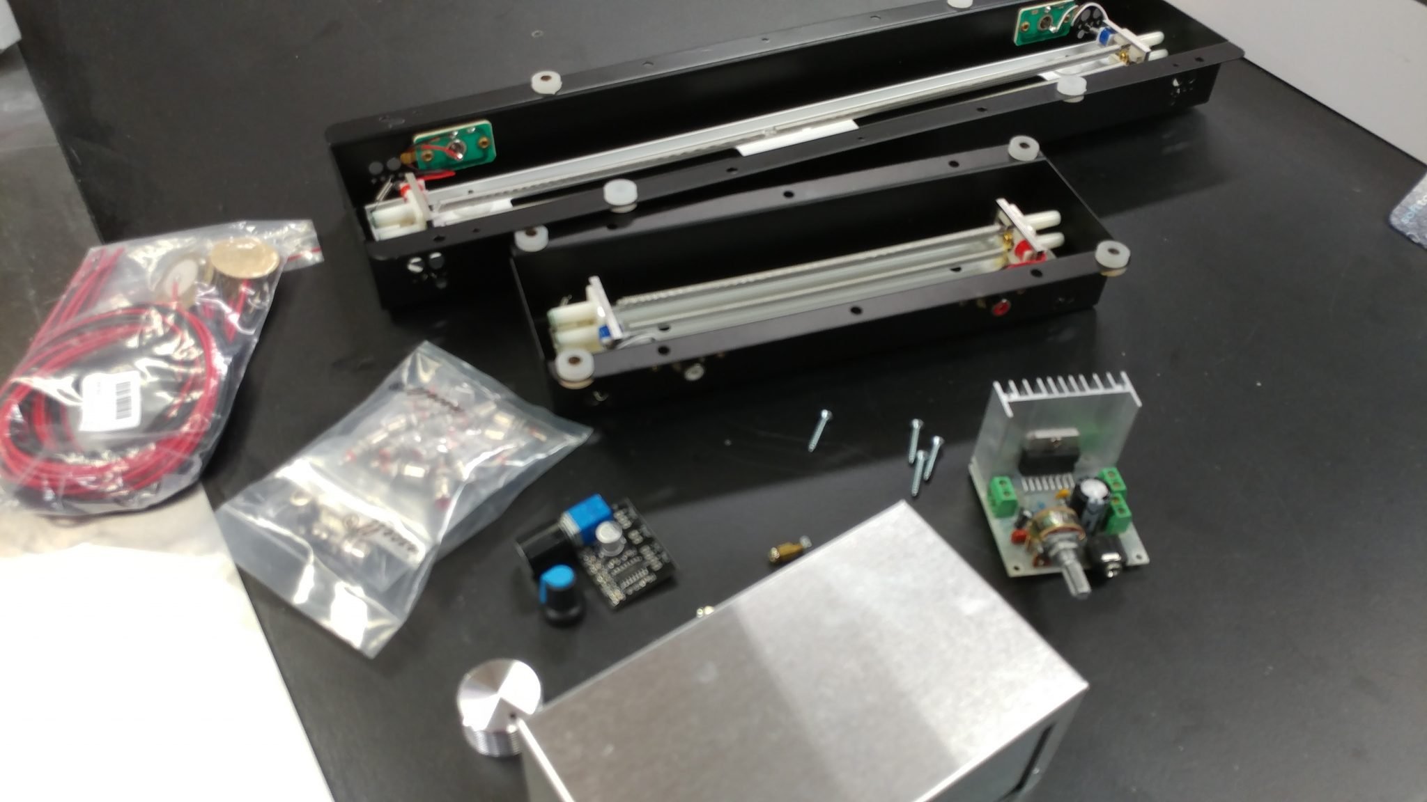
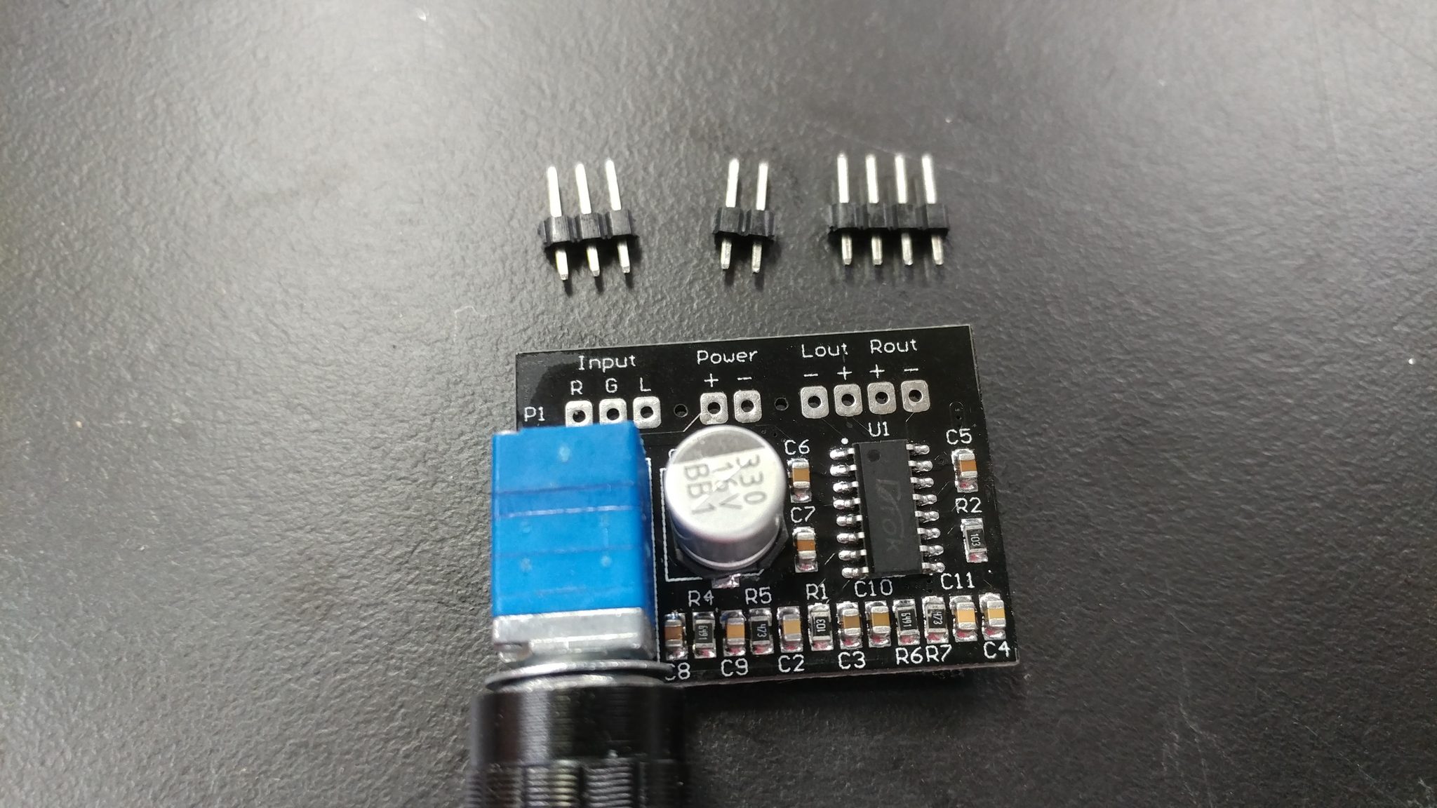
This version is going to have two channels, each with its own reverb tank which will result in each channel having its own sound. I started by gathering the necessary parts. Here’s what I’m using:
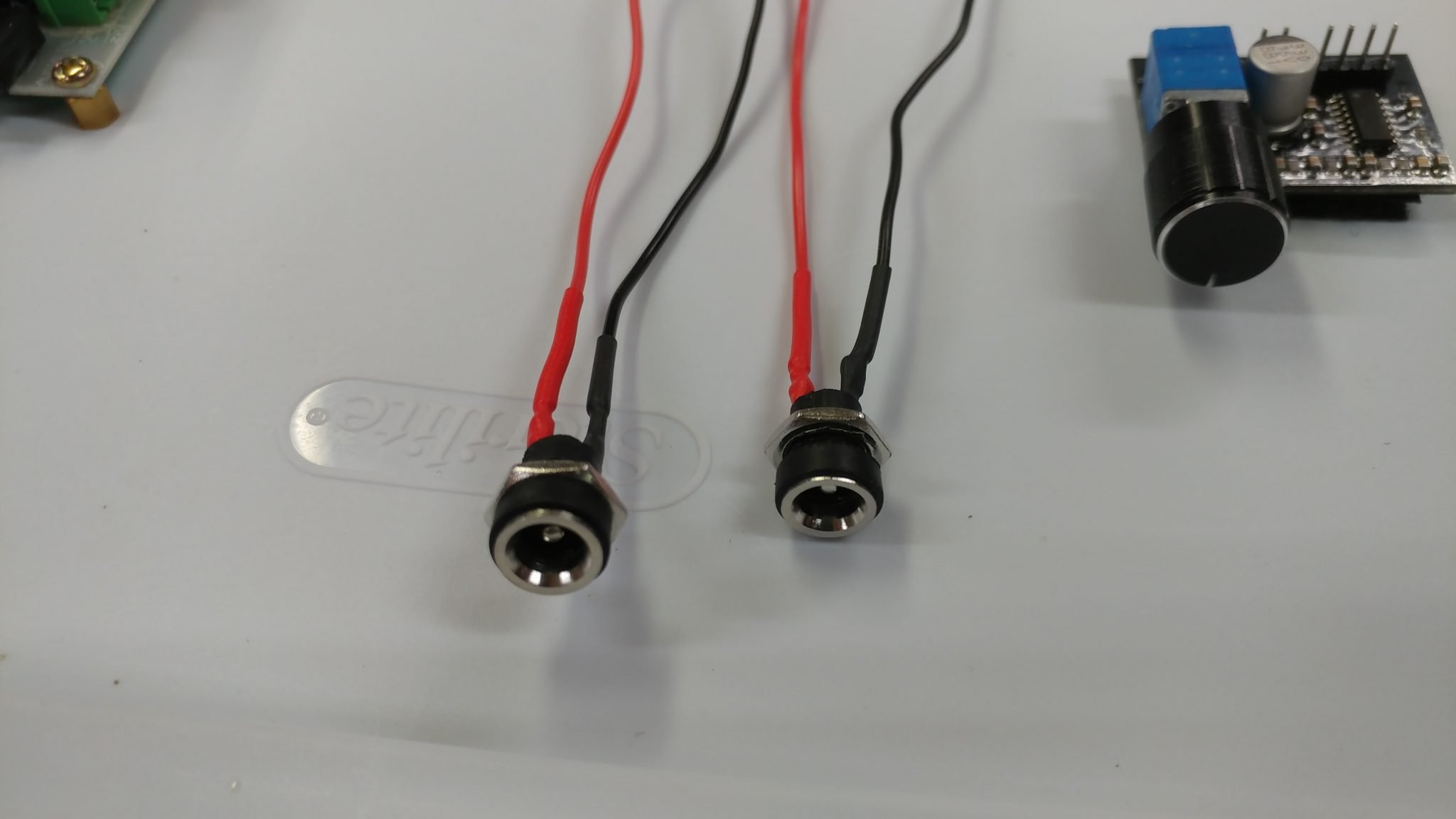
5.5 mm X 2.1 mm power jacks (X2)
Power supply: 5 VDC 2 Milliamp
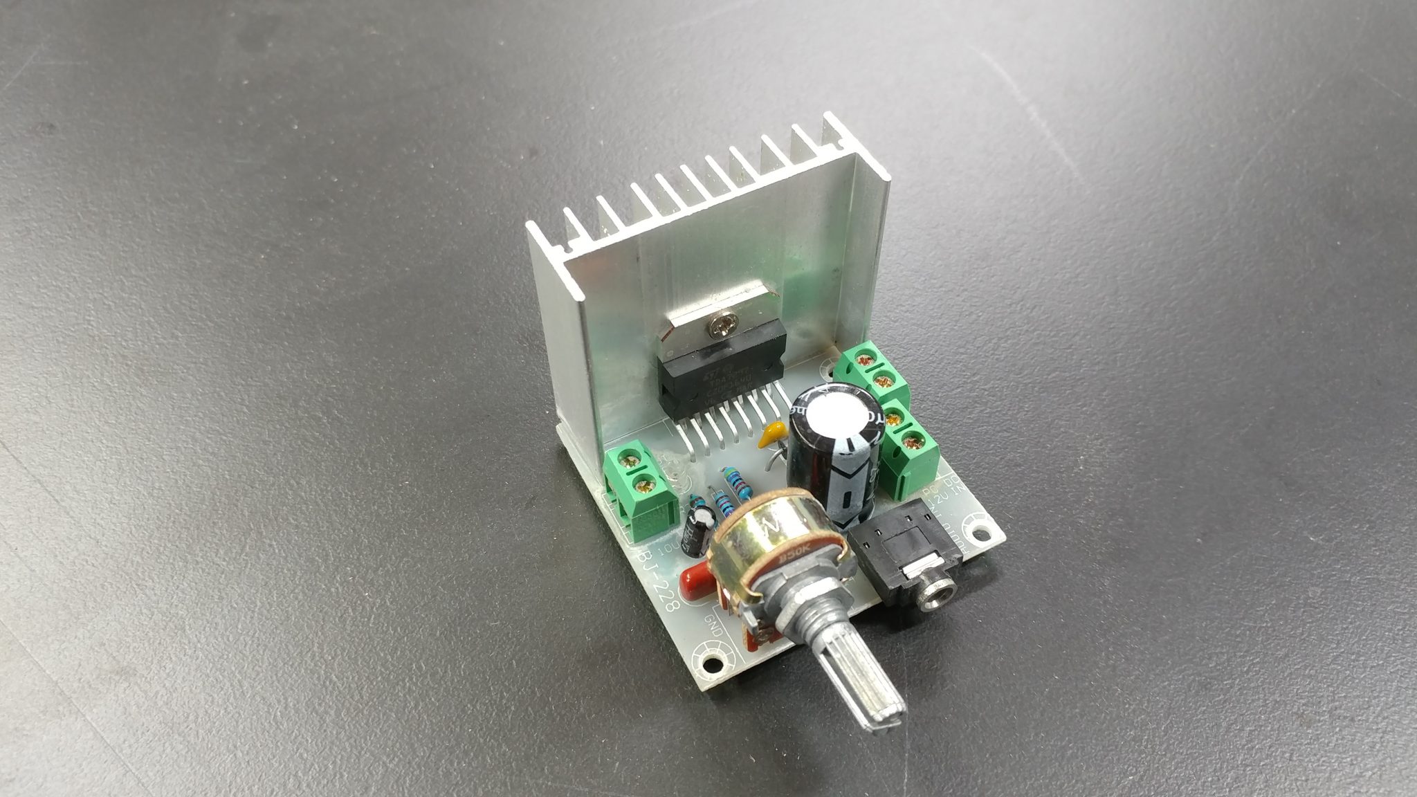
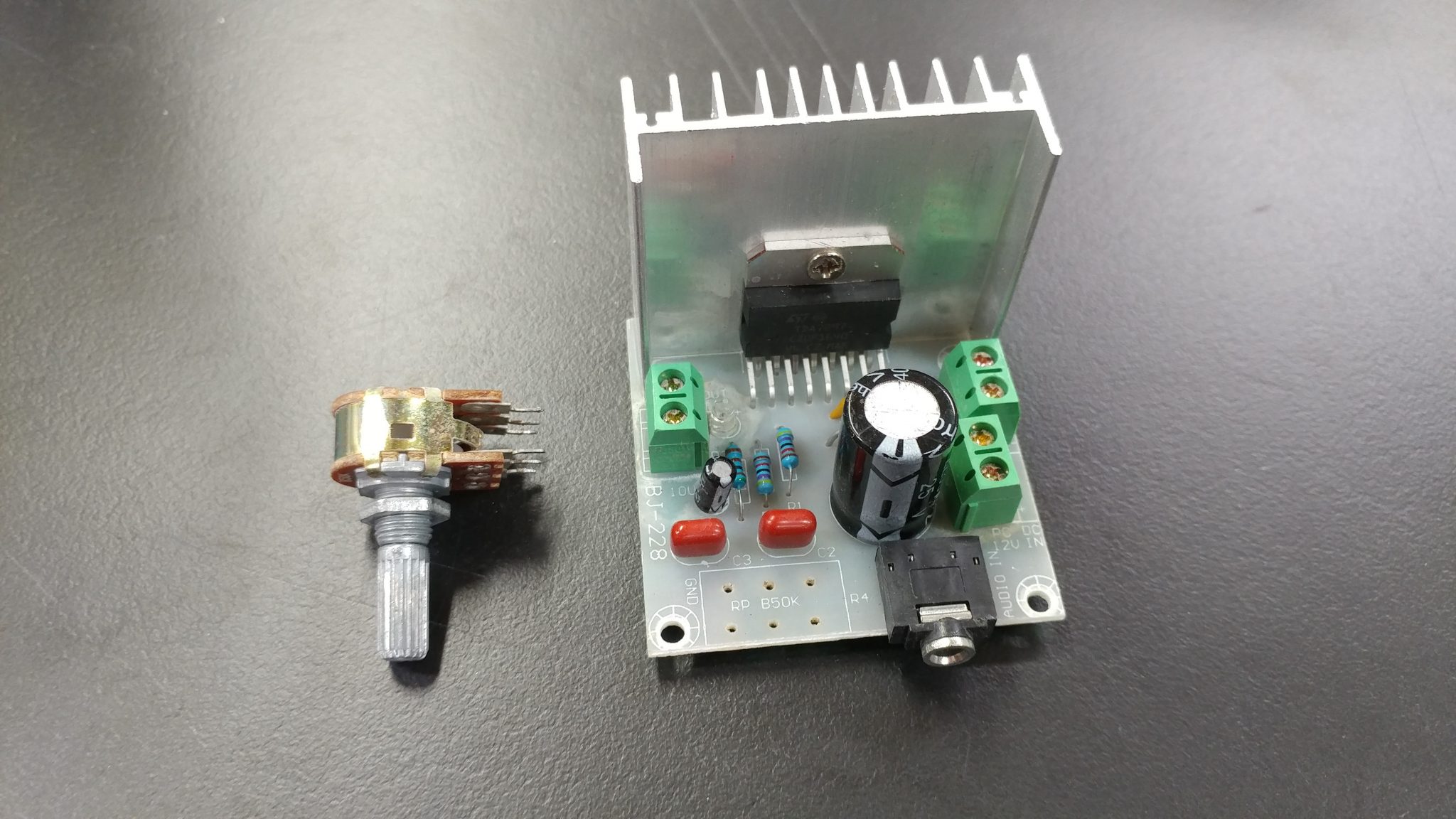
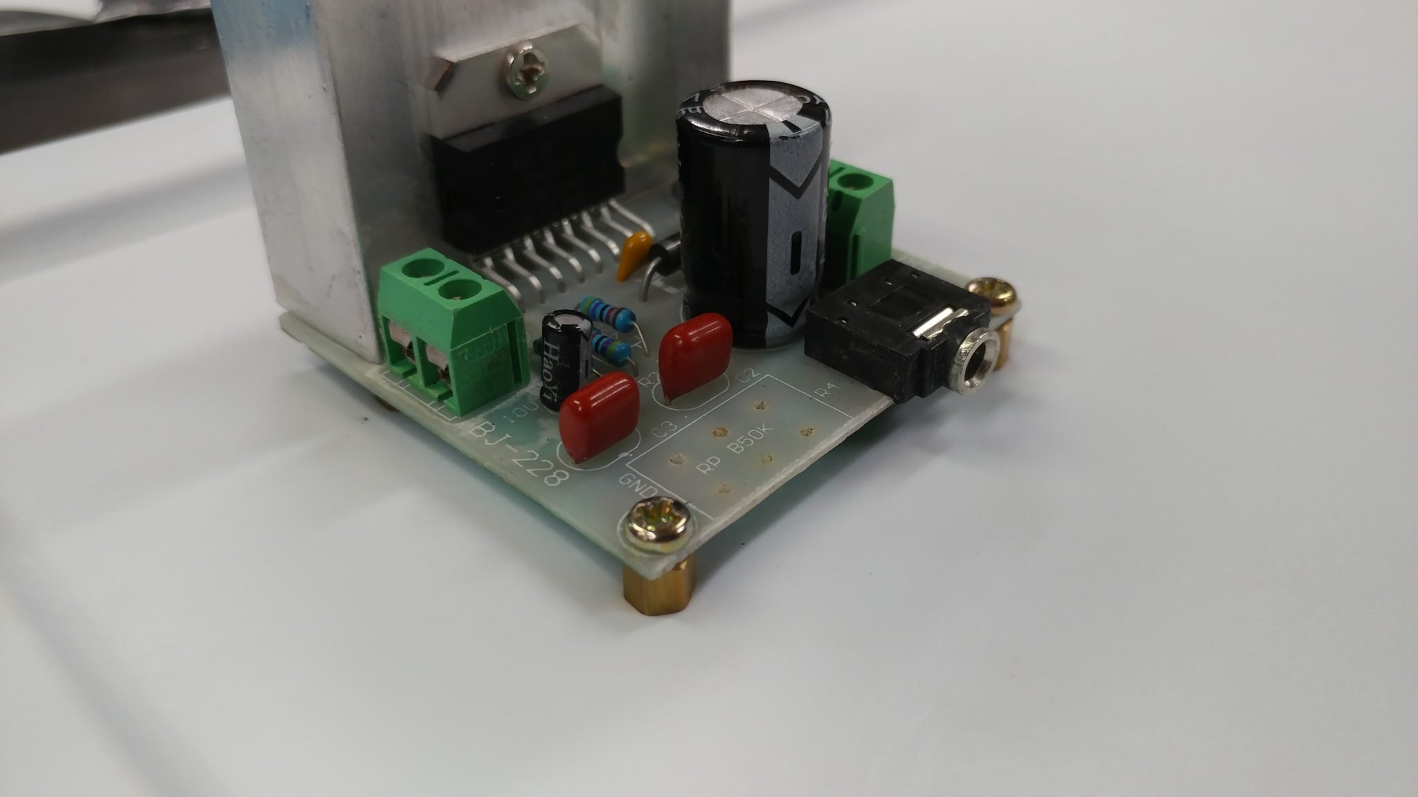
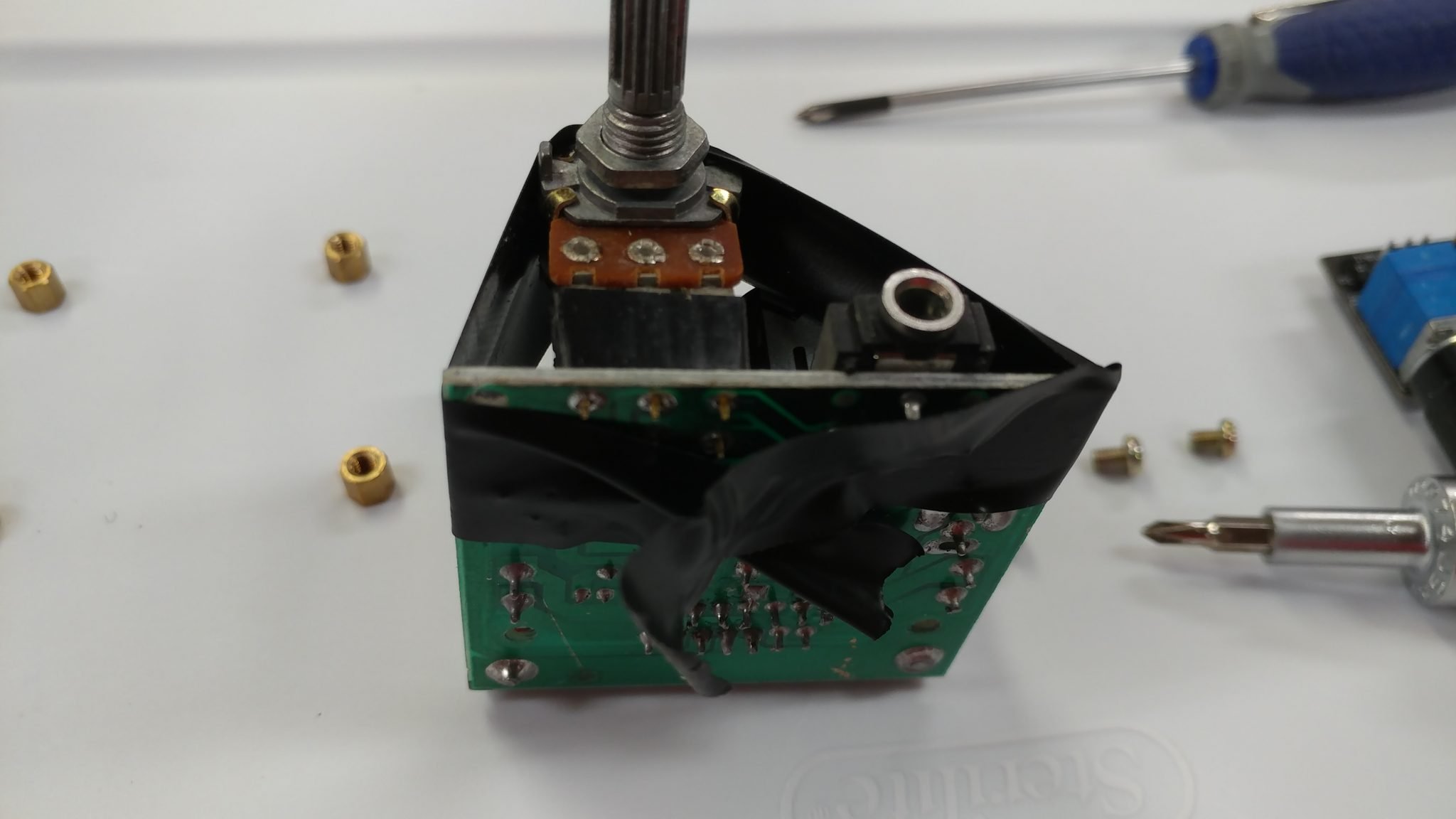
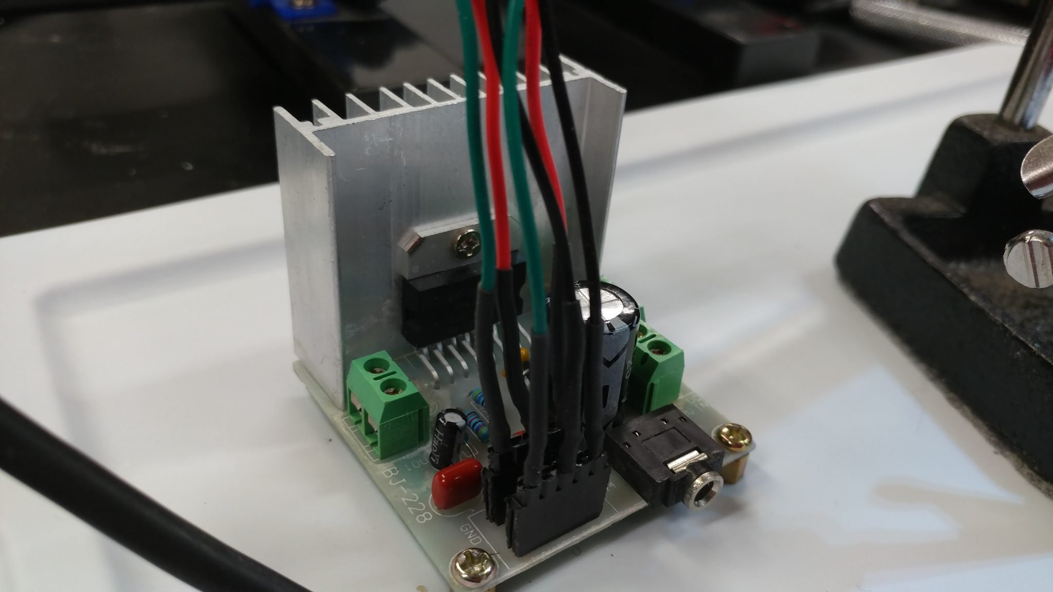
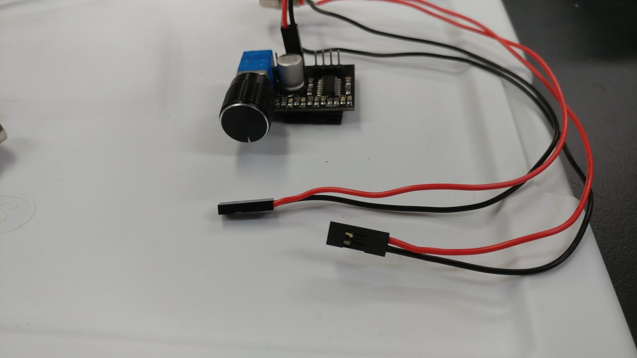
The output amplifier has an volume potentiometer. I want to have access to this while using the instrument but you’ll notice that there is also an 1/8″ jack right next to it on the board. This is the input. Unfortunately, I don’t want this sticking out the front of the instrument so I decided to remove the potentiometer so I can attach it with wires and locate the actual volume knob away from the board.
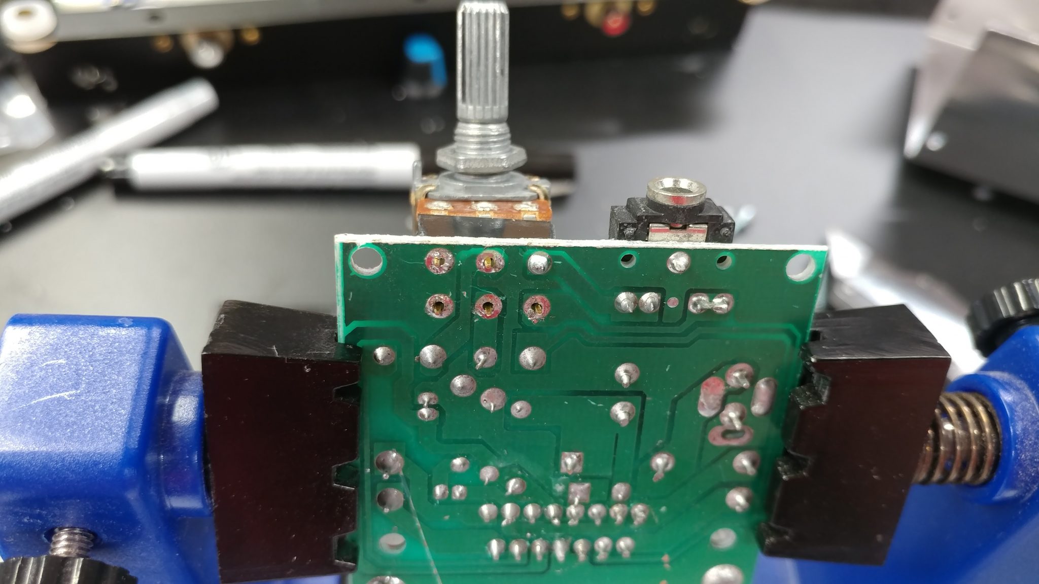
Looking at the underside of the board you’ll see that it should be easy to de-solder and remove the potentiometer.
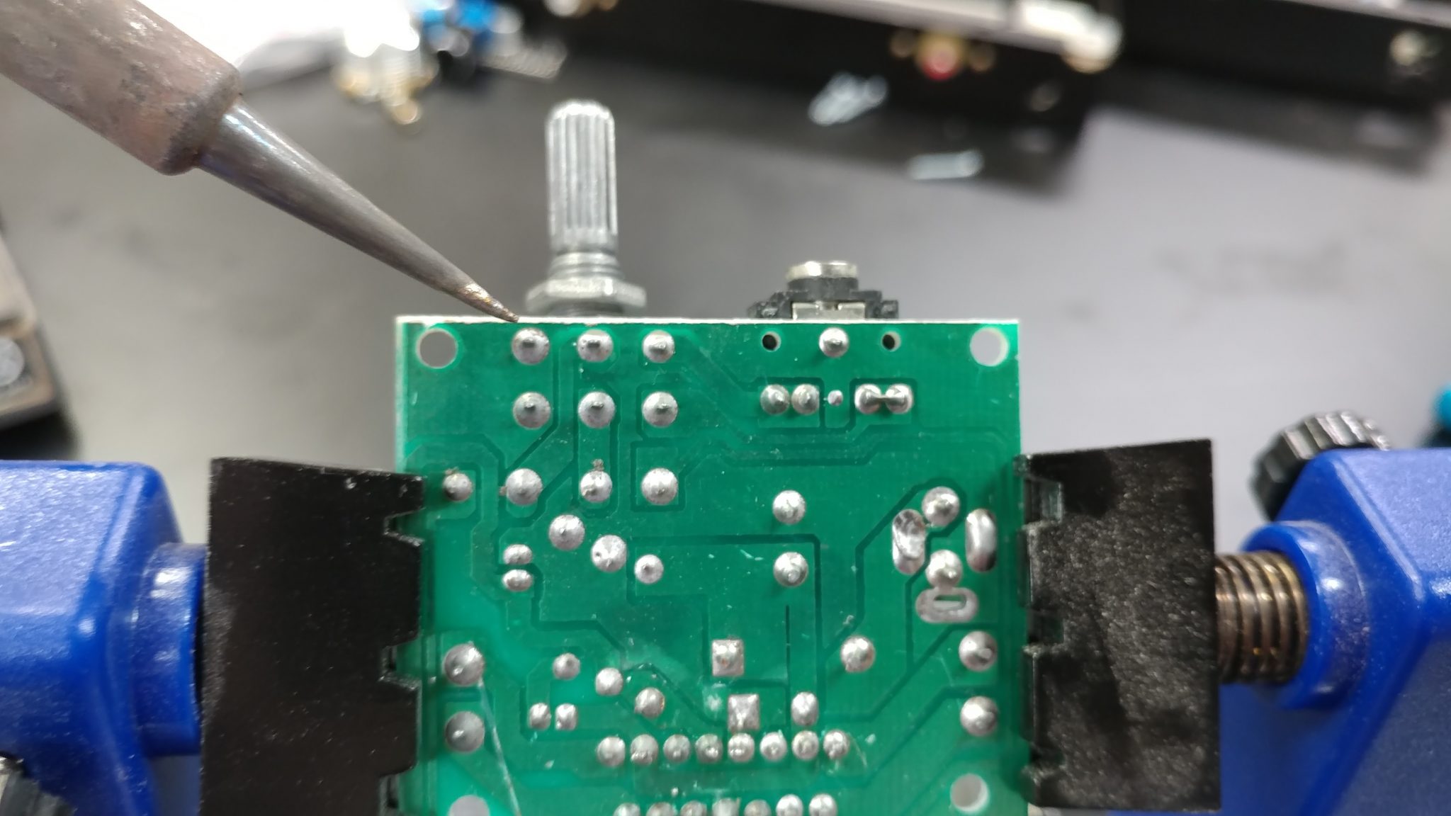
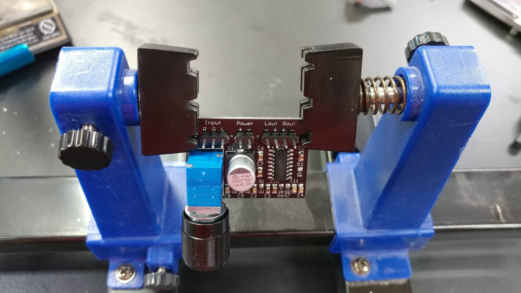
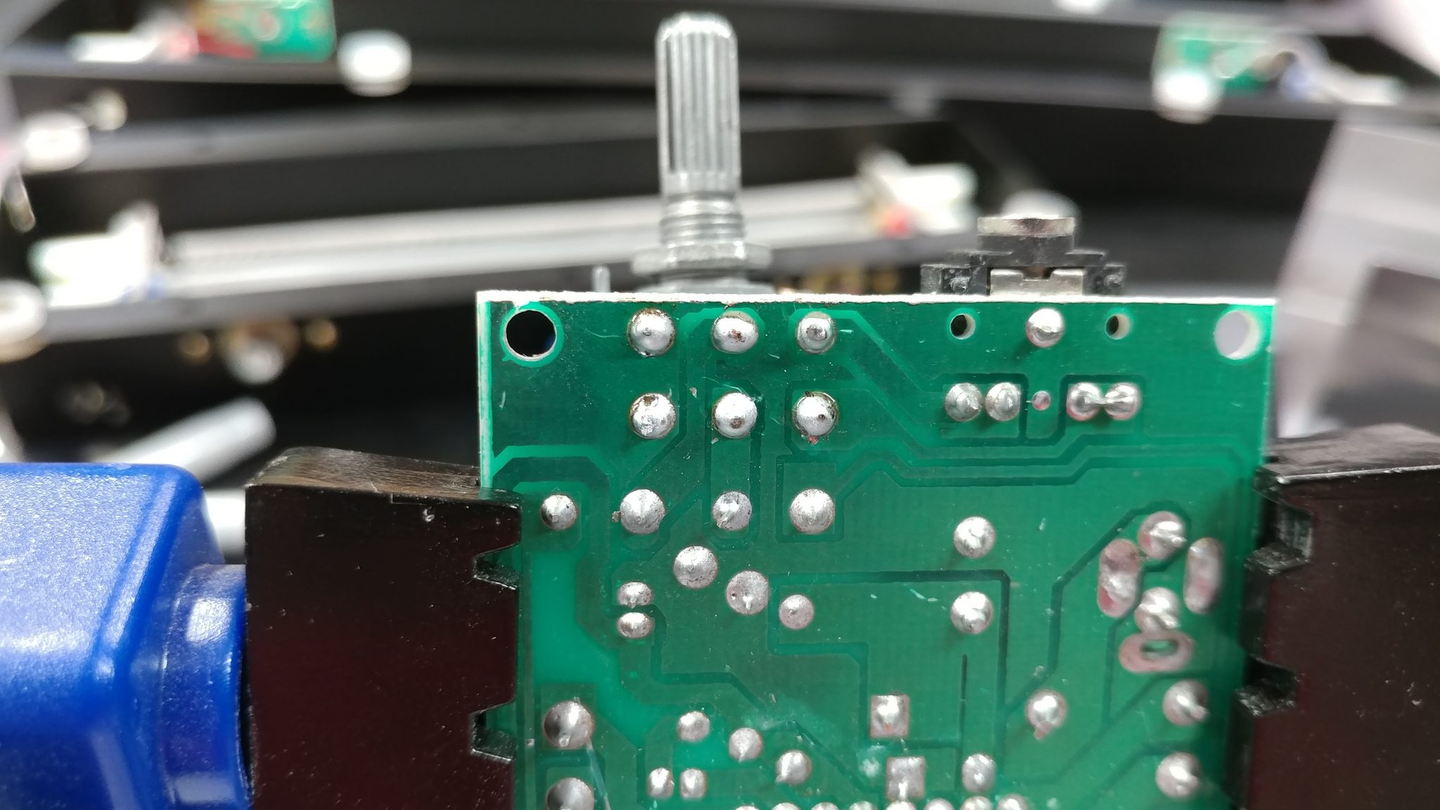
The potentiometer has been successfully removed.
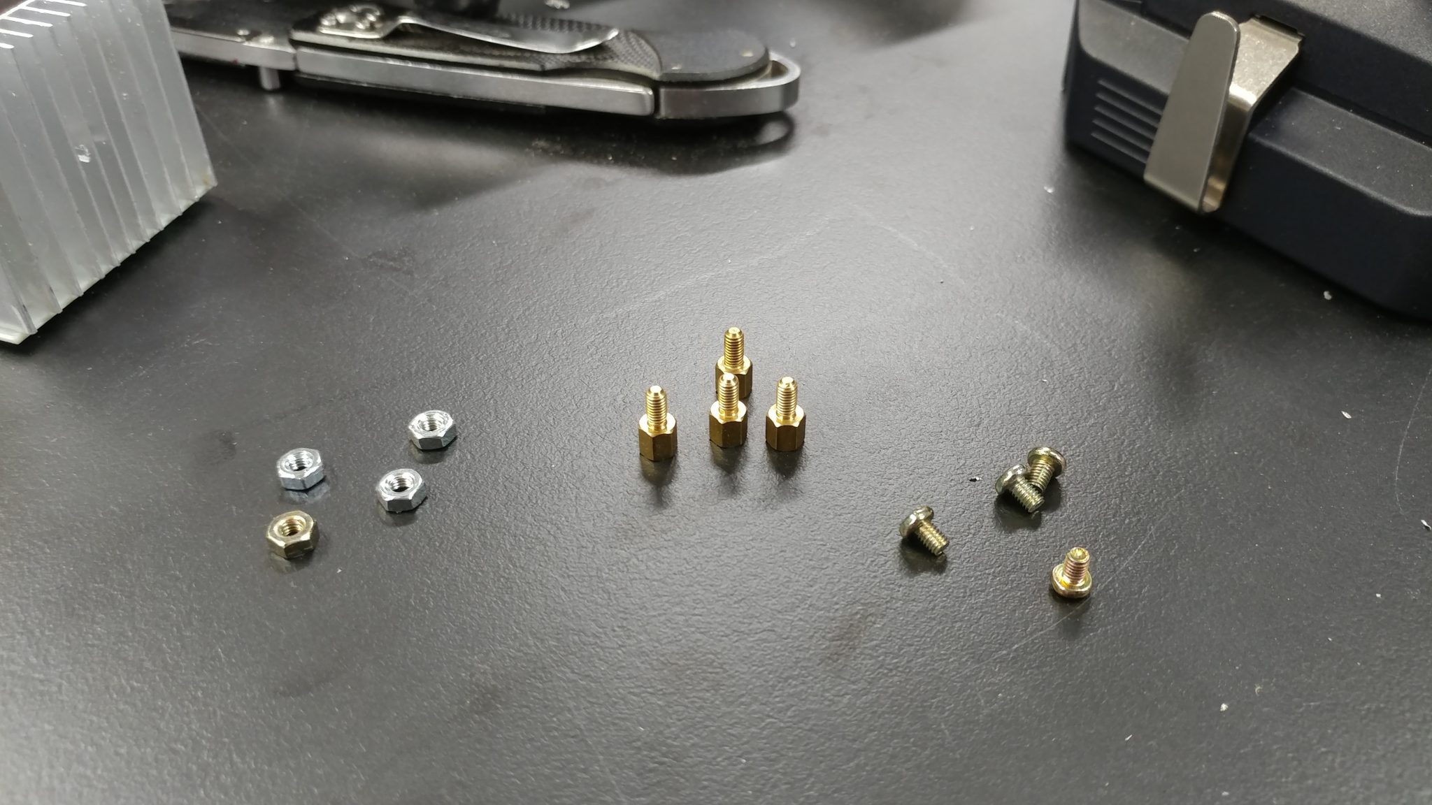
I’m temporarily securing the board to a surface by using screws and standoffs.
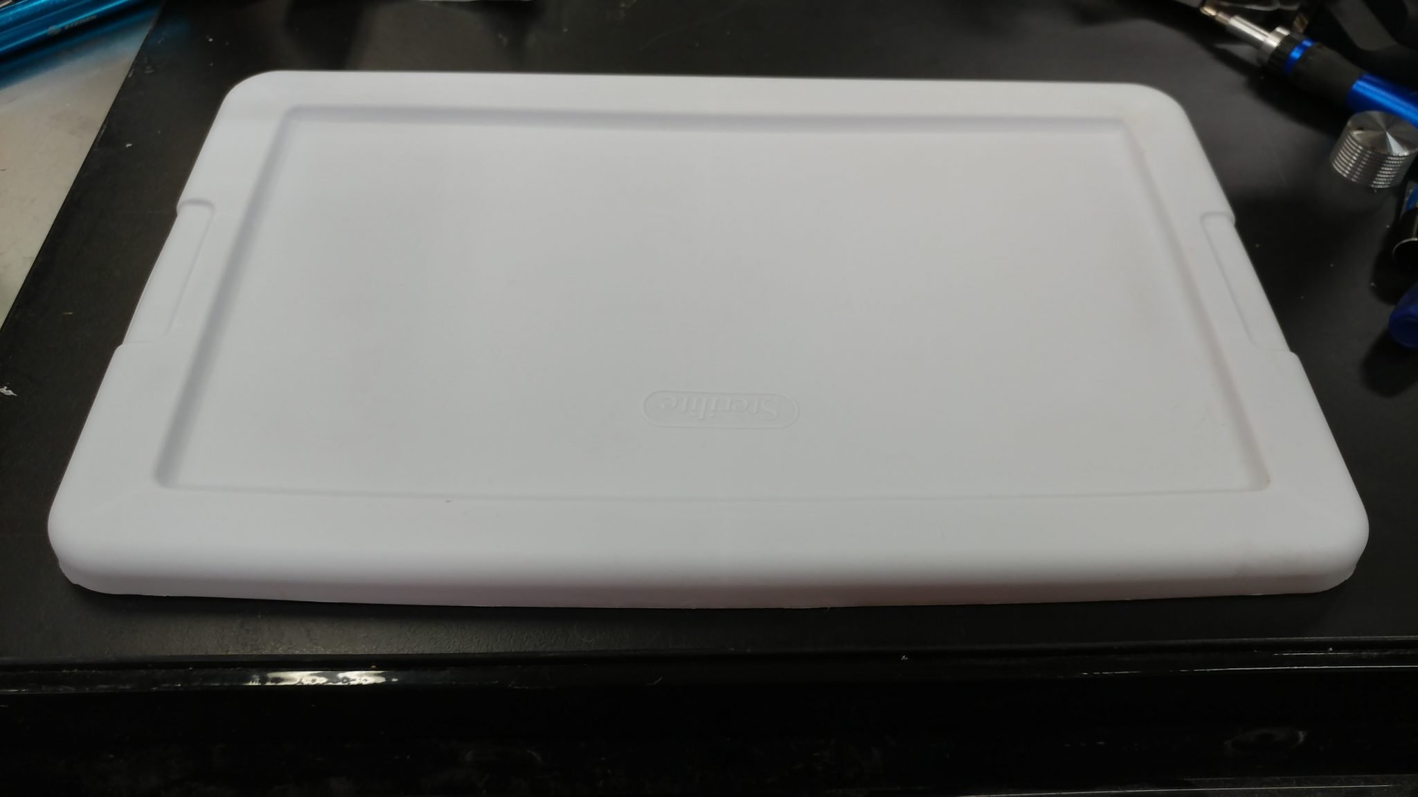
One of my favorite tricks when prototyping electronics is to use those $1.00 storage bins. At first I decided to attach everything to the top of the lid. I changed my mind later, which you’ll see.
I attached the standoffs to the board and used that to mark where I needed to drill holes in the lid for the board.
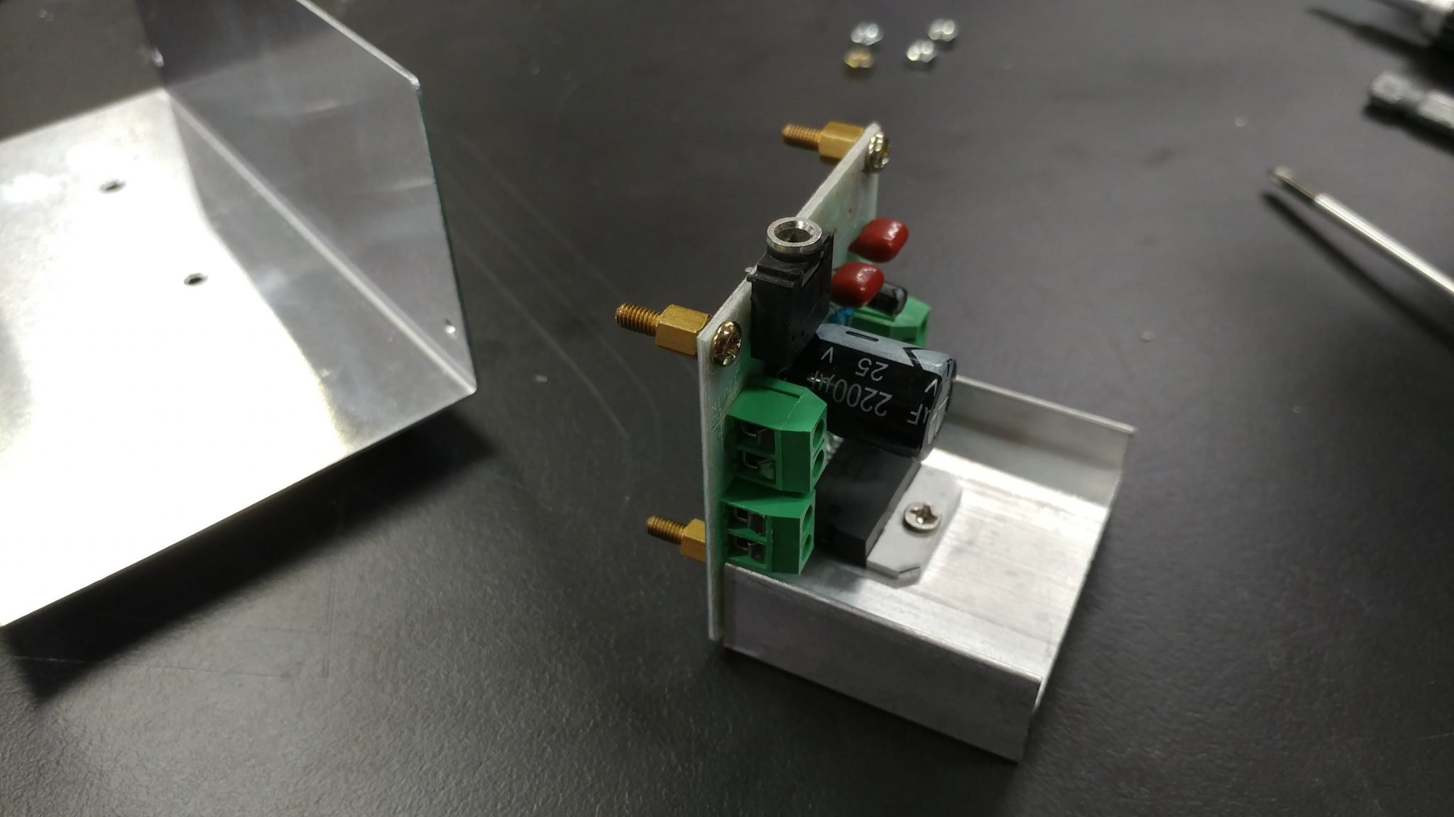
I drilled the holes then inserted the legs of the standoffs then secured them with nuts.
The input amplifier is a bit different. It’s pretty small and doesn’t have holes for standoffs. I also don’t necessarily need to access the potentiometer on this board as I expect to set-it-and-forget-it.
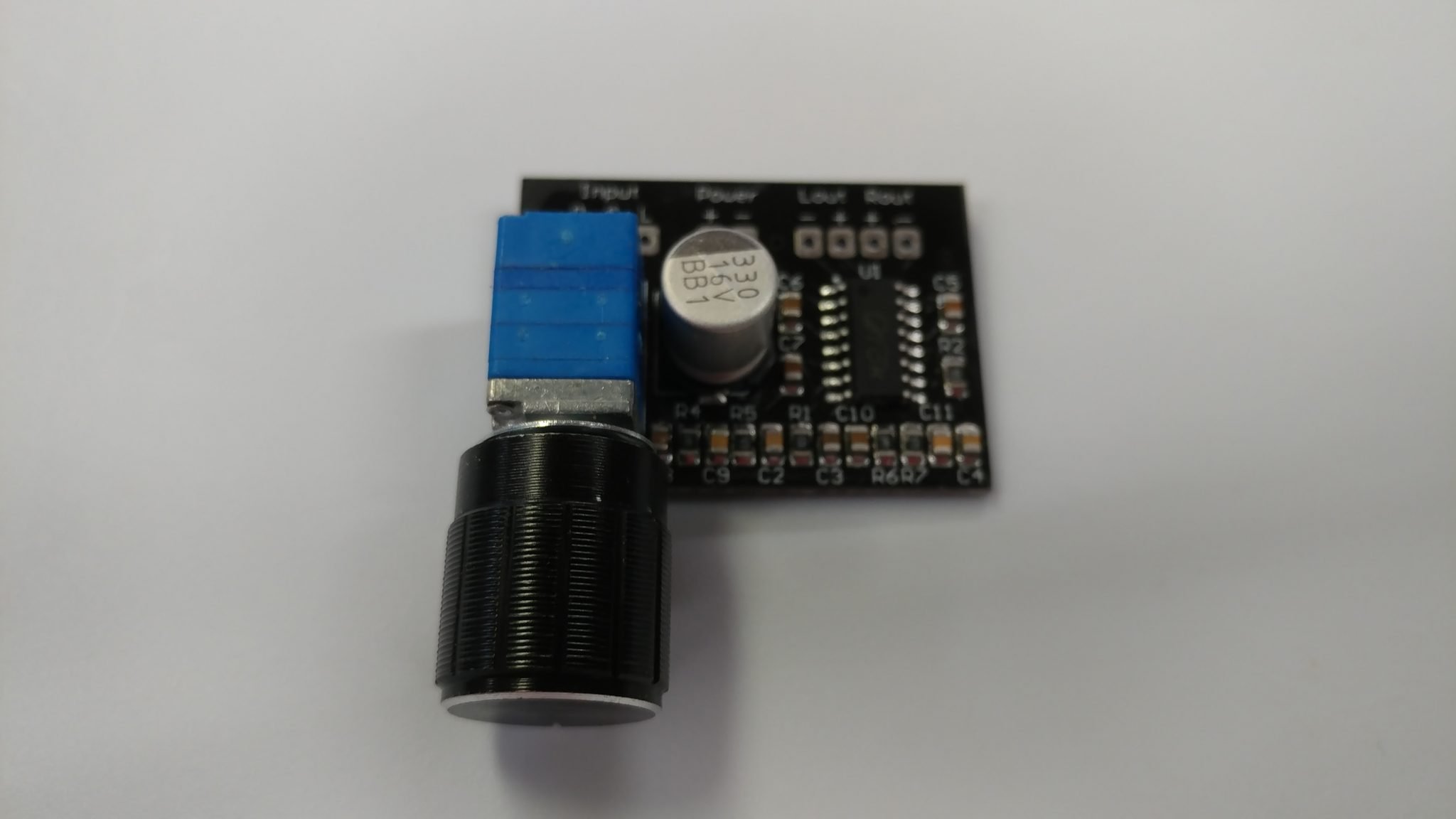
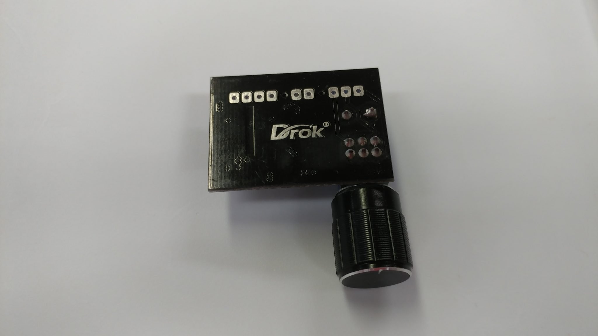
Looking at the underside shows a spot where there aren’t any traces so I decided to secure this board with sticky-backed velcro.
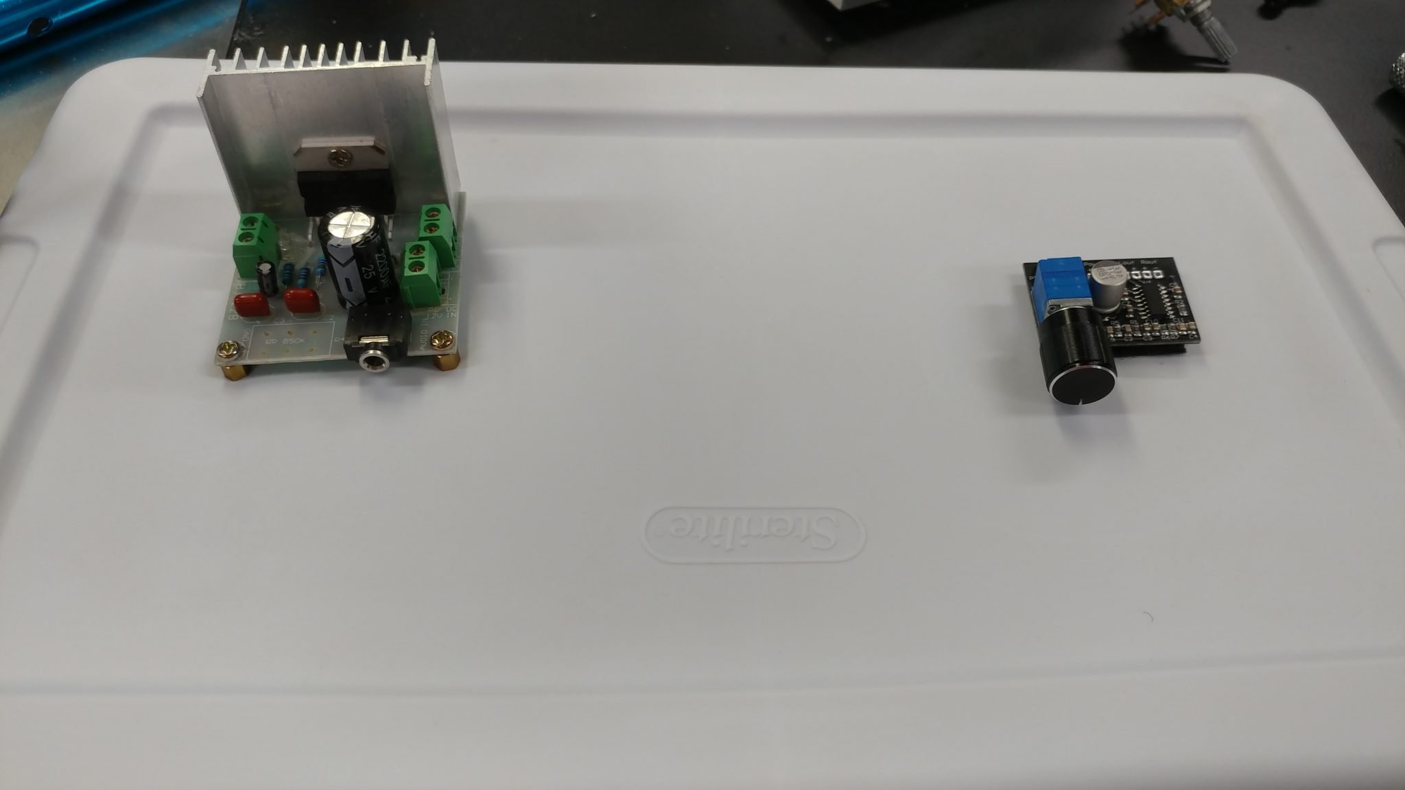
Both boards are secure and ready for some prototyping.
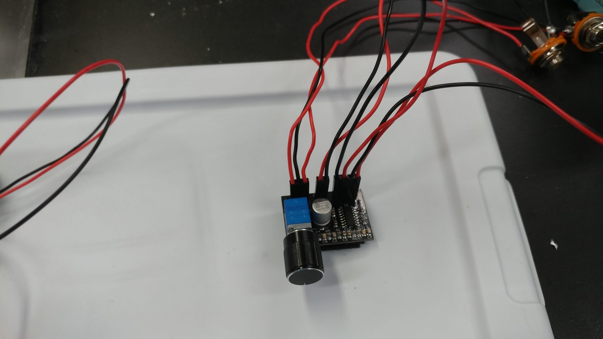
The board requires the installation of header pins.
Easy enough.
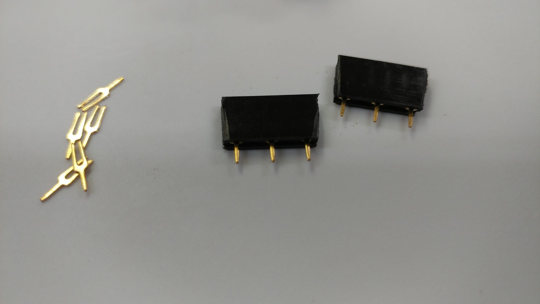
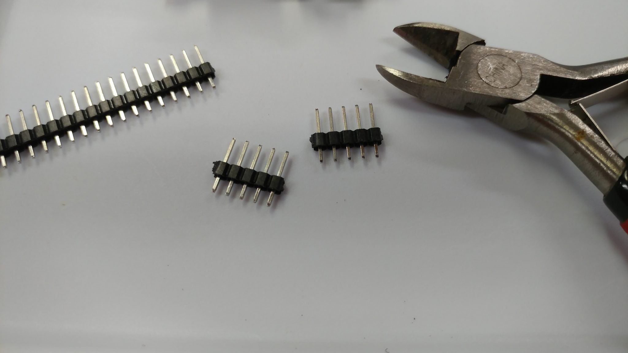
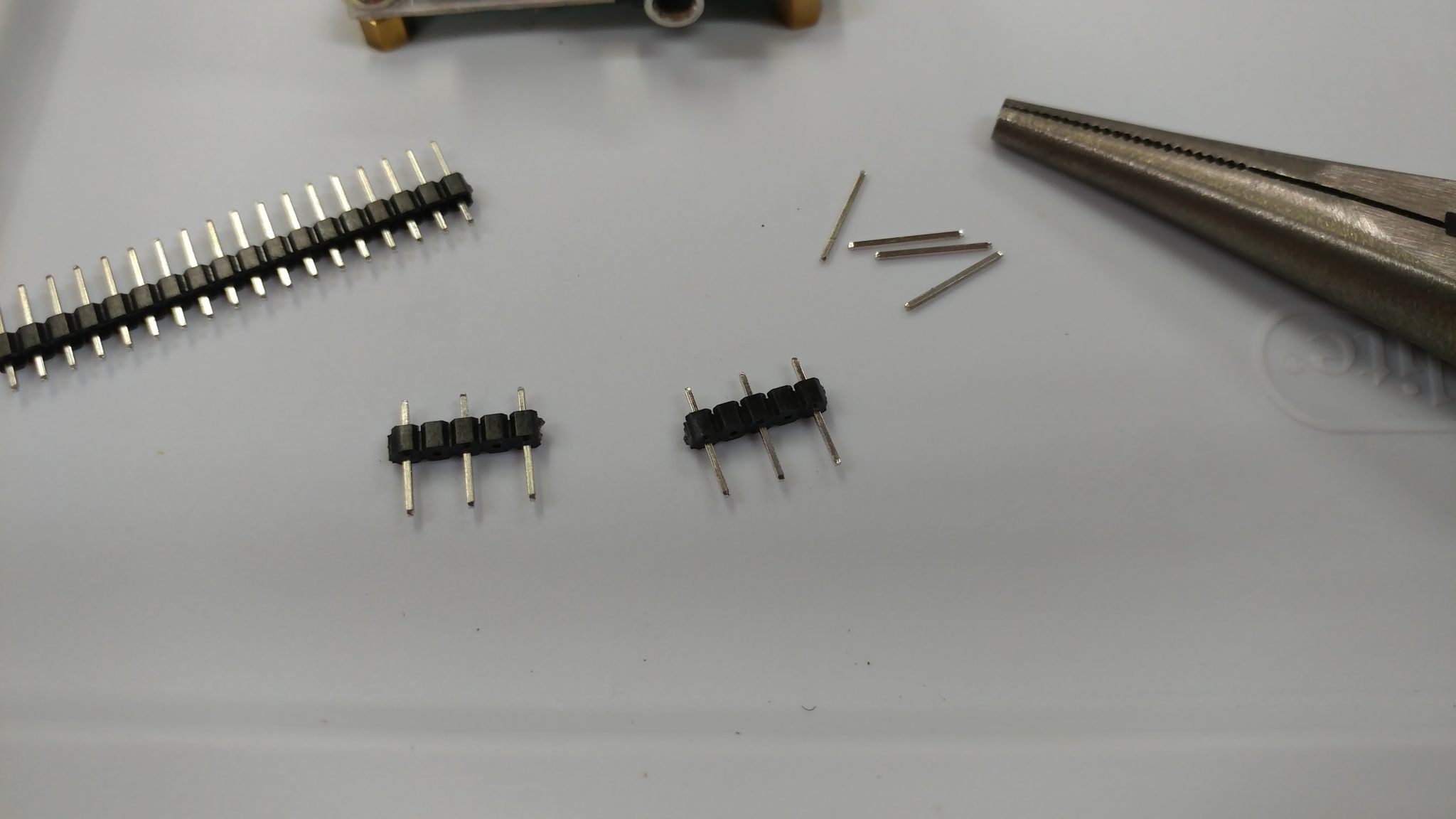
To attach the potentiometer to the output board, I attached some female headers to the board. I started with some 5 pin sections. I only need three of them but they’re double-spaced so I need to start with 5 and pull out the 2nd and 4th pin with needle-nosed pliers.
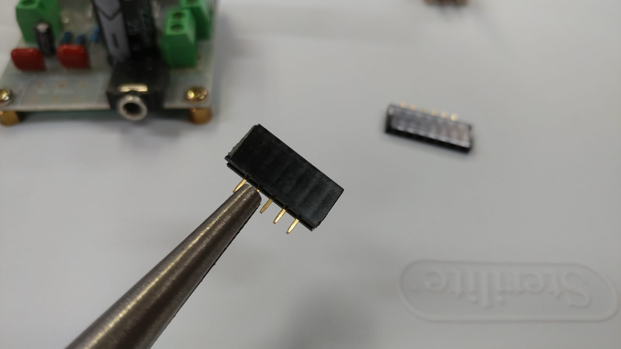
This results in 3-pin headers that I can solder to the board.
To hold the headers in place, I inserted the pins for the potentiometer in the headers and then I held the potentiometer to the board with some electrical tape just long enough to secure one of the pins.
After the pin was secure, I removed the tape….
…and soldered the remaining pins.
To make the plug that will insert into the headers, I started with a length of header pins. Using a pair of snips, I made two five-pin sections.
I removed the 2nd and 4th pins just like I did on the female headers.
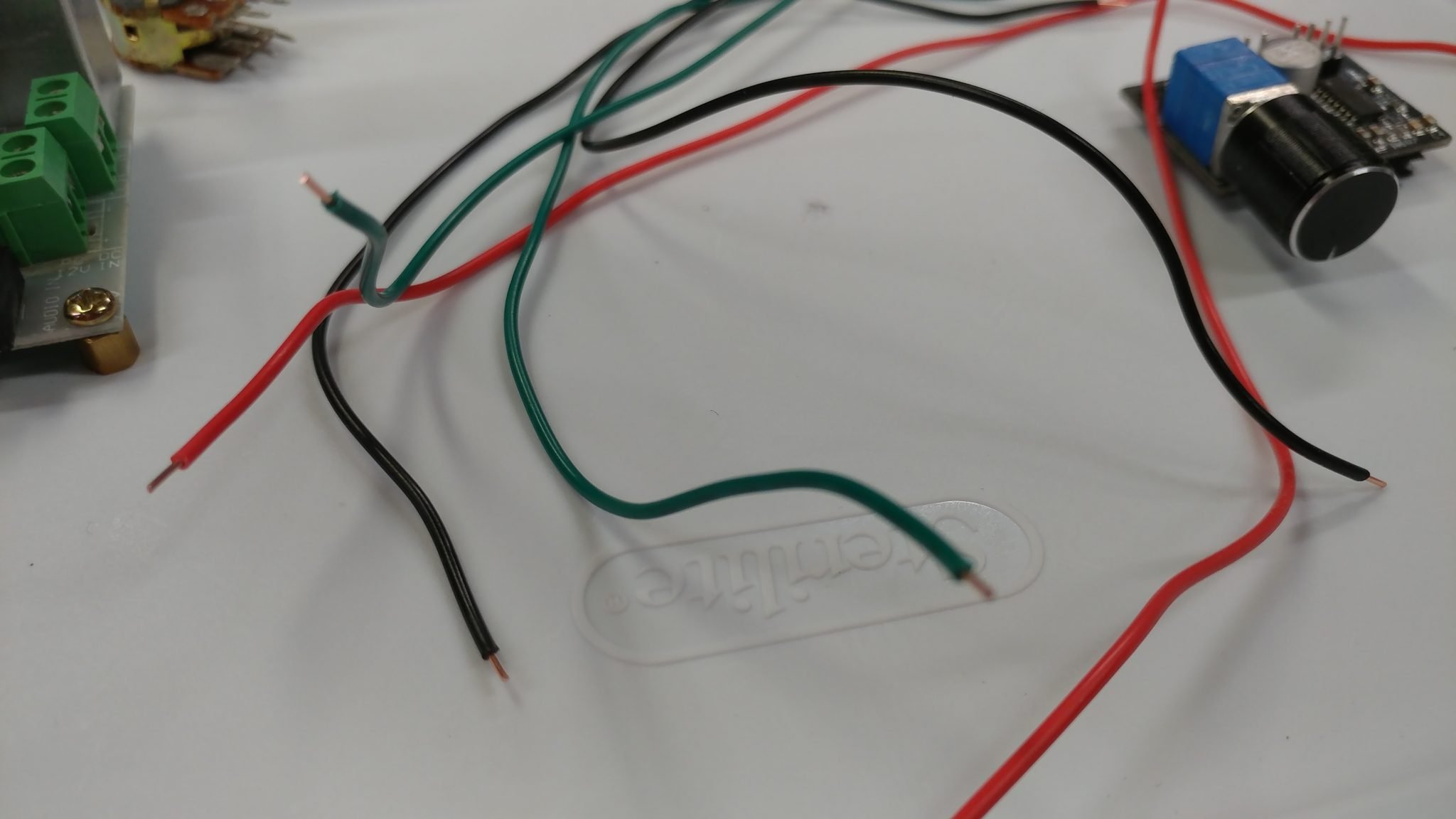
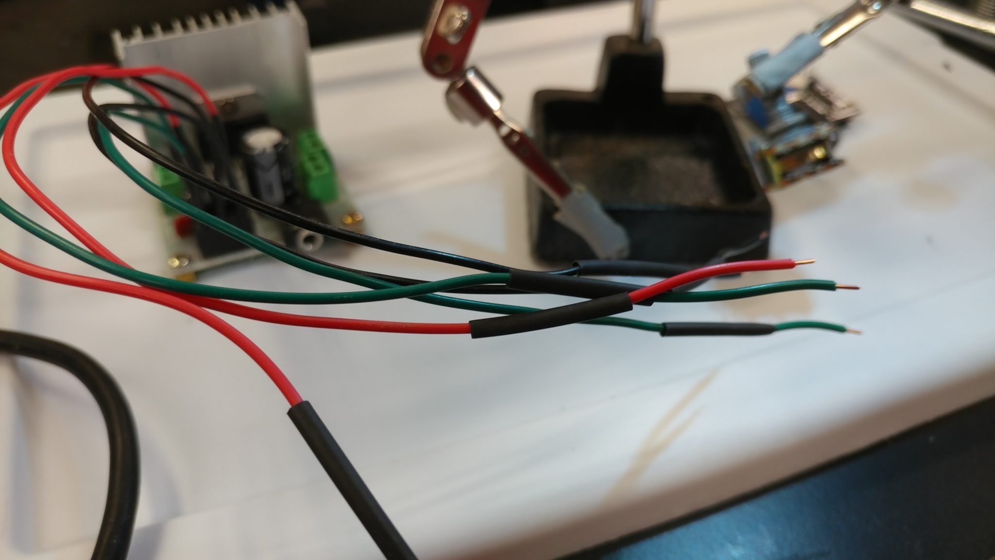
I made a cable out of 22 awg wire. I normally try to do some sort of color scheme that makes sense so I decided to have the left most pin on each row connect to a green wire, and the other two pins to both connect to either a read or a black wire. I started by cutting some lengths of wire. Then I stripped the ends.
I soldered the wires to the pins.
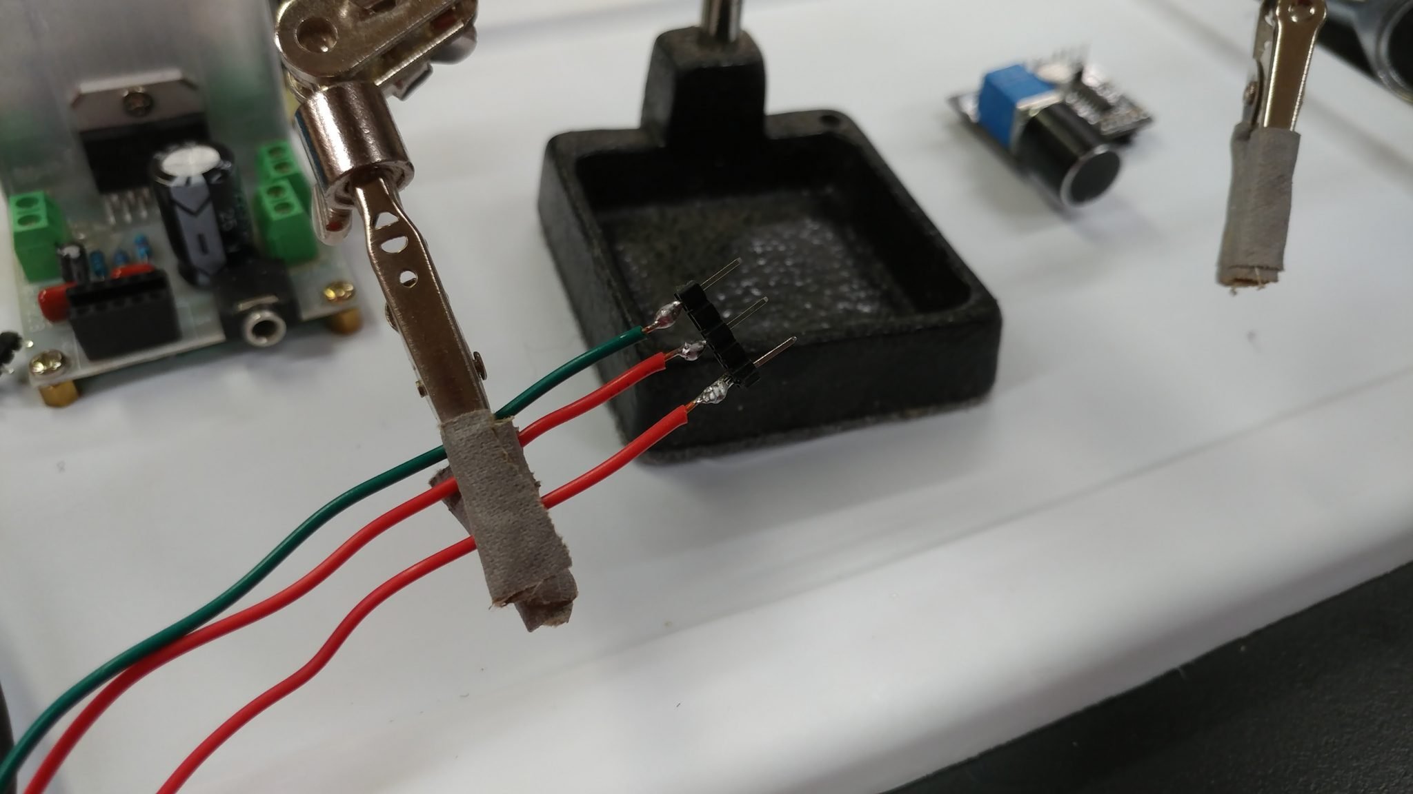
Then I covered the bare connectors with heat-shrink tubing.
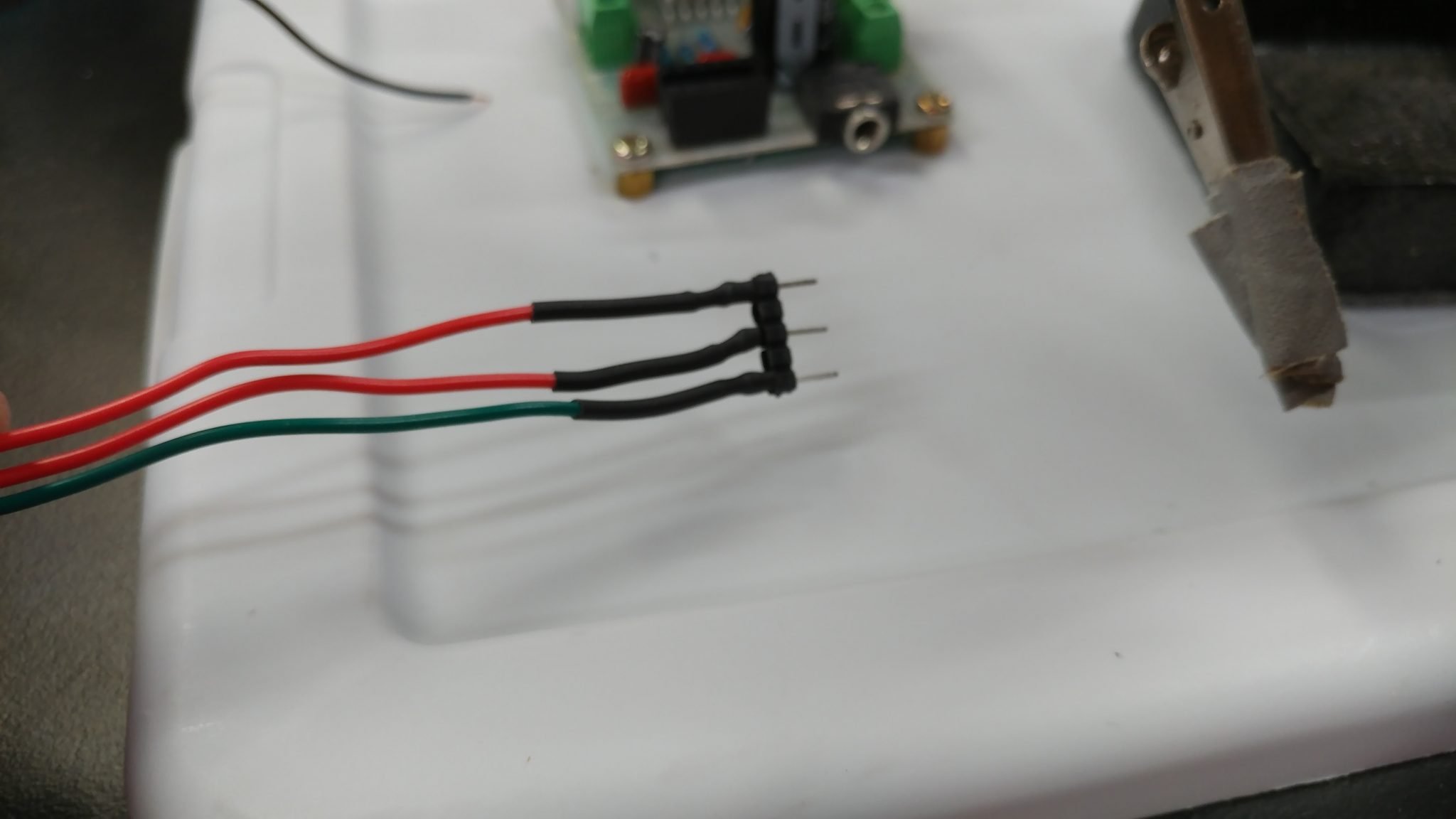
Both cables are attached.
Anyone who’s made their own instrument or mic cables can relate to this: always remember to put any sleeves on the wires BEFORE soldering the other ends on.
I soldered the wires to the potentiometer then applied the heat-shrink tubing.
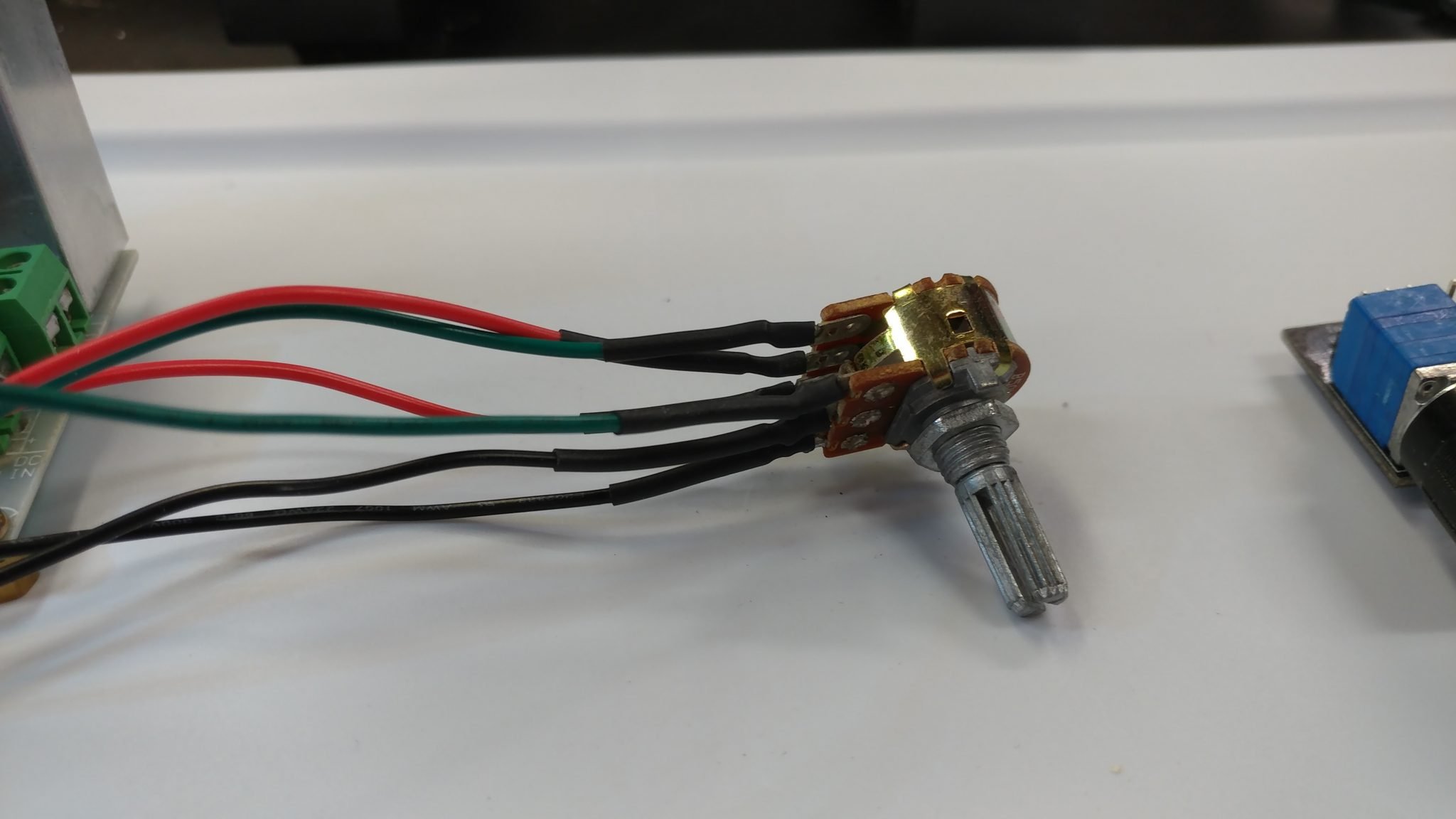
Now I’ve got a volume knob that I can attach away from the board. This may not work, however, as I explain later.
Each board will use its own power supply. The output amp needs 12 VDC at 2 Amps while the input amp only needs 5 VDC ad 500 Milliamp. I tried to find an easy way to get different connectors so I don’t accidentally connect the 12 VDC supply in the input amp and damage it, but it’s pretty hard to get the correct power supplies with the connectors that I wanted. Until I come up with a better solution, this will have to do.

I soldered wires and applied heat-shrink tubing.
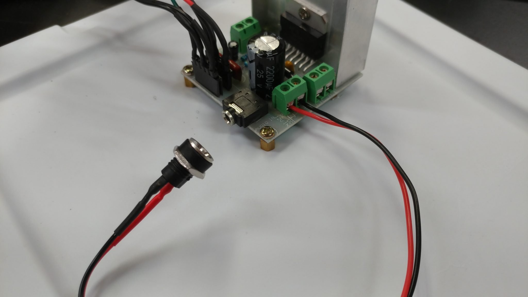
The wires for connecting the power jack to the output amplifier are pretty simple to attach.
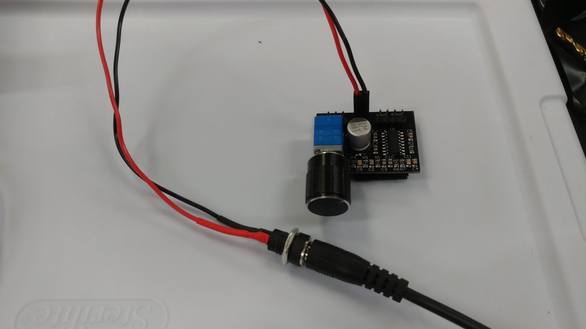
To connect the power jack to the input amp board, I need to add a 2-pin connector.
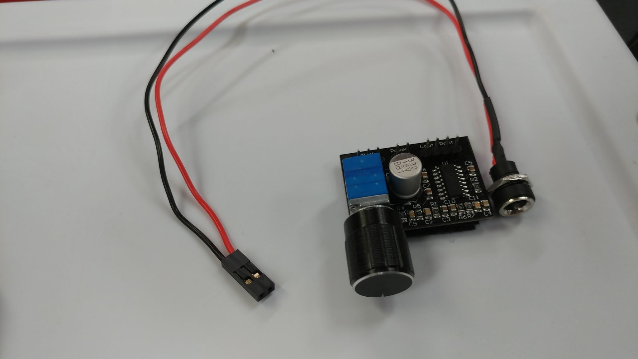
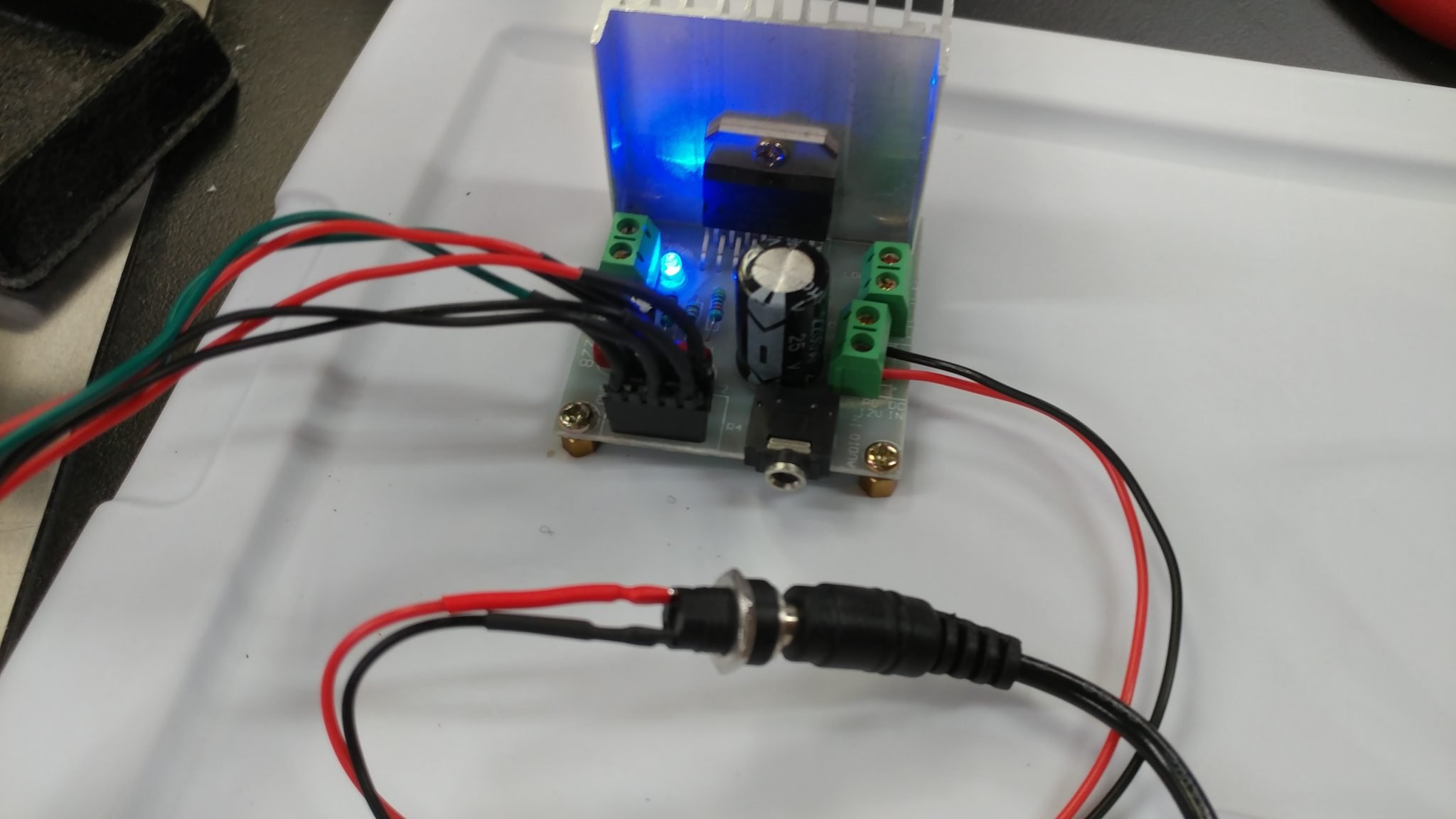
The power cable connects to the two pins on the board. I plugged in the power adapter but there isn’t an indicator on the input amp so I don’t know yet if I wired everything up correctly.
I plugged the power adapter in to the output amp and it all seems to be working.
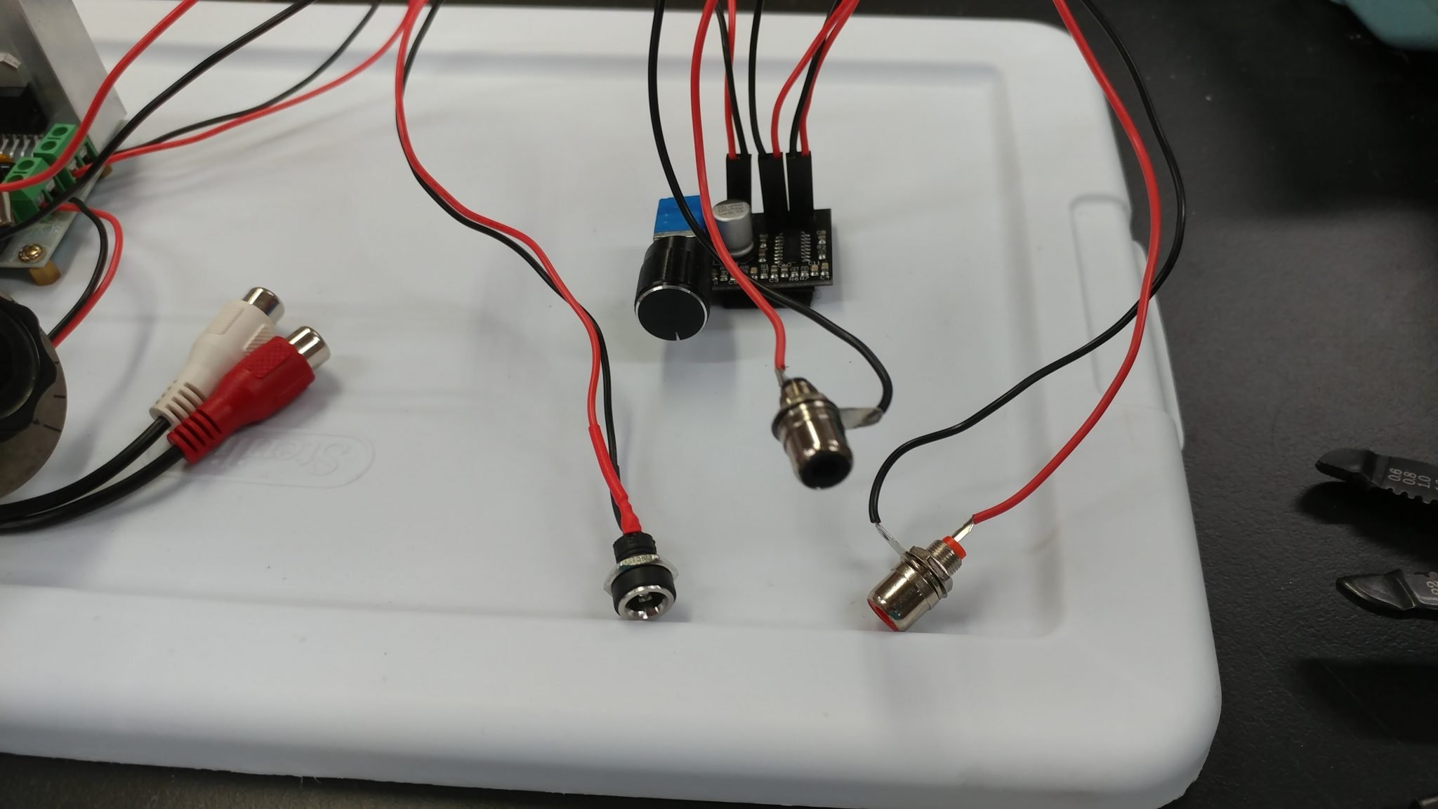
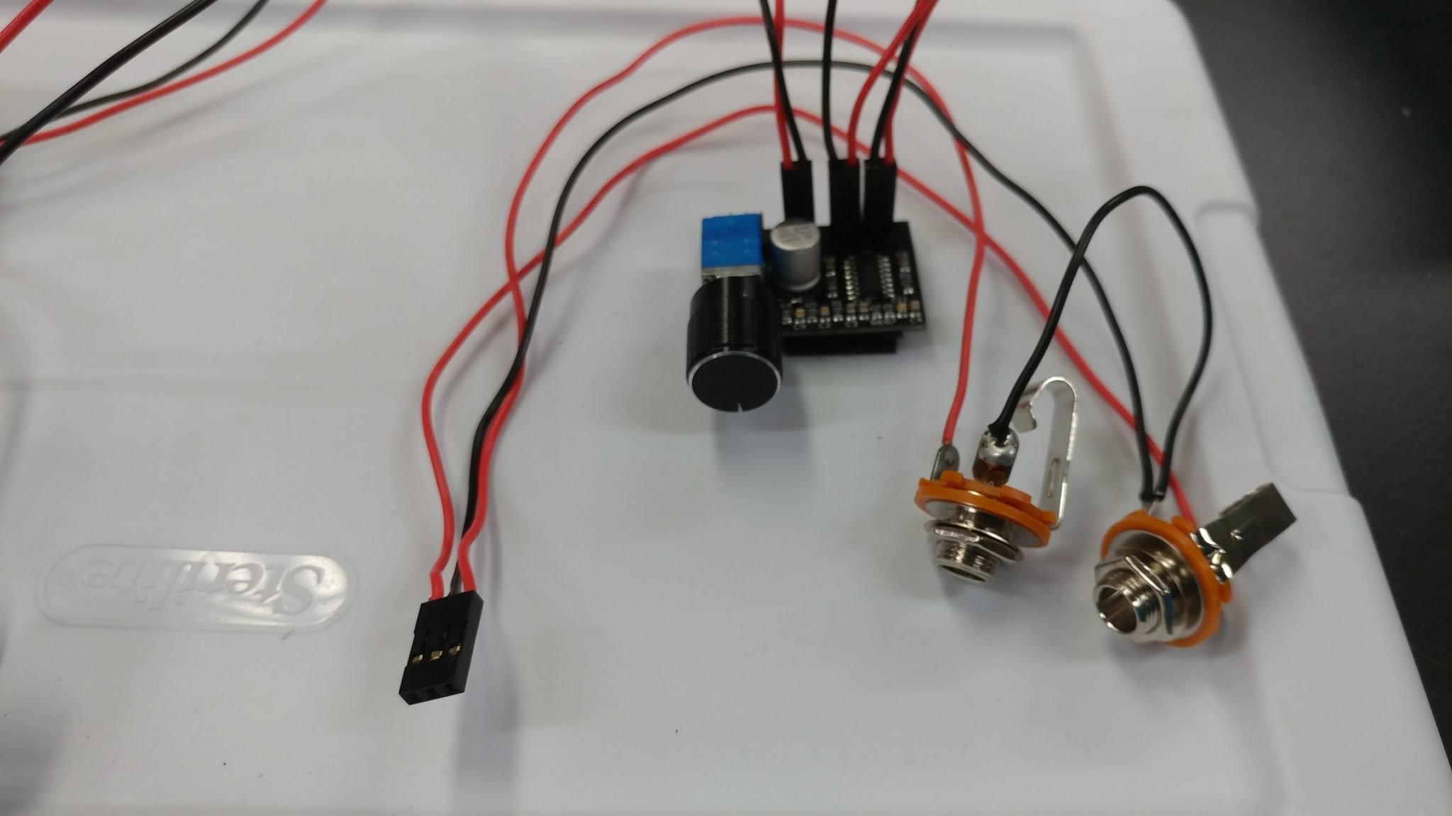
Now it’s time to get some signals into and out of the prototype. I’m hooking up four 1/4″ TS jacks, two for input and two for output.
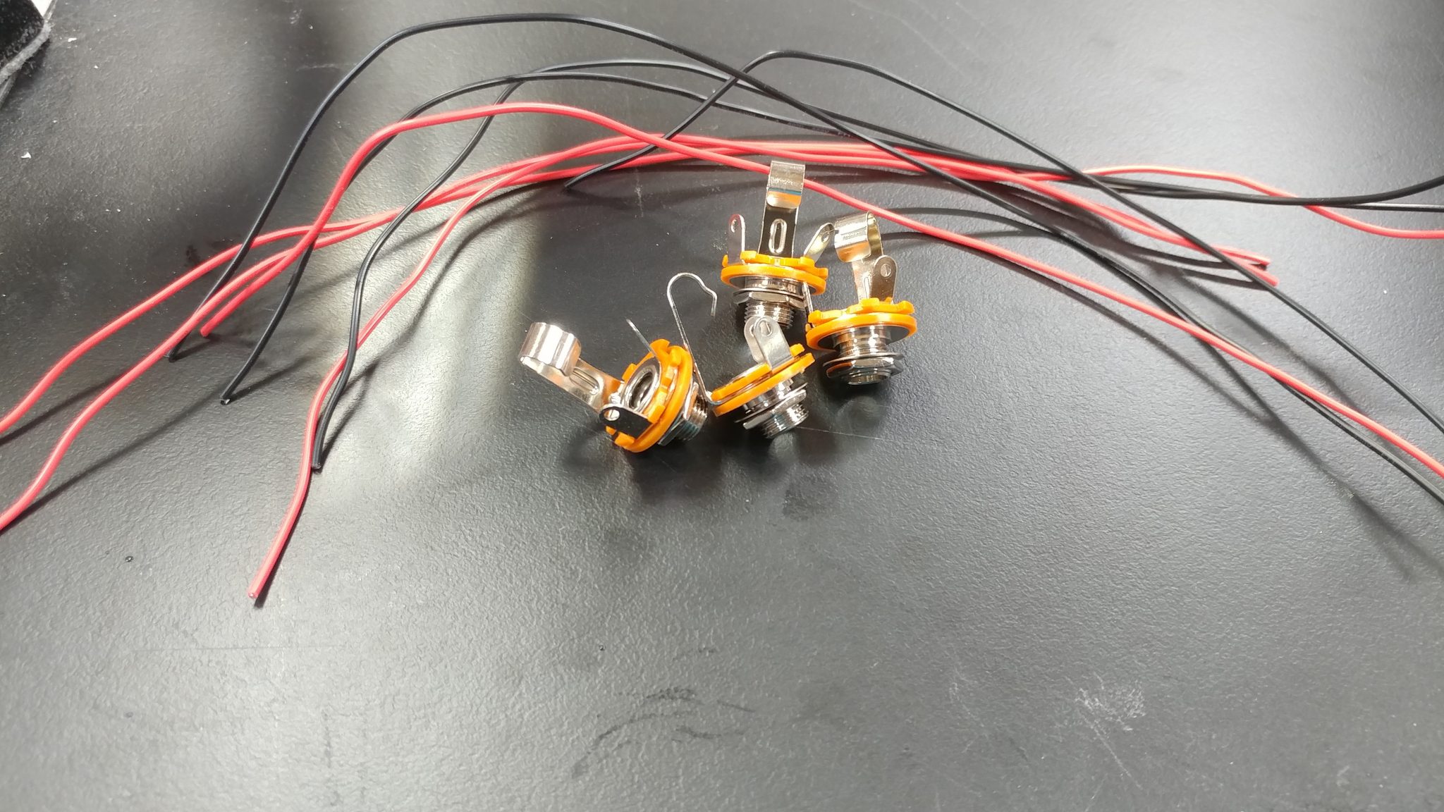
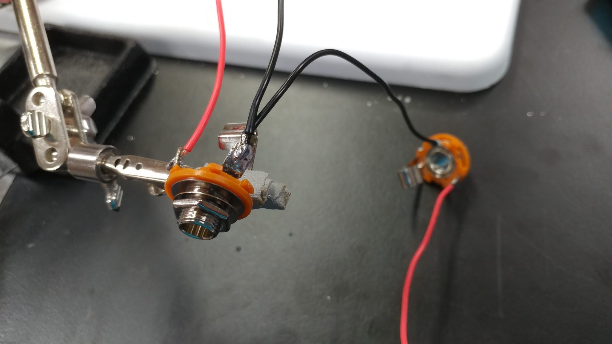
I tinned the tabs on the 1/4″ jacks then attached both wires.
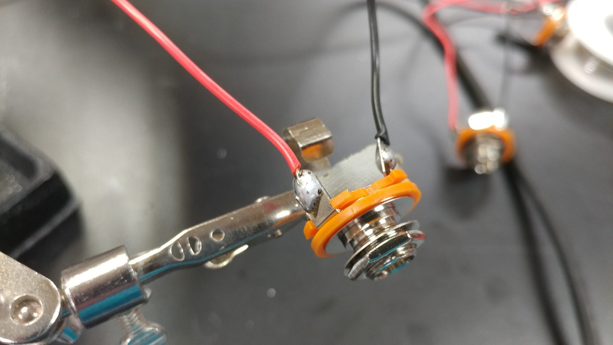
They each connect easily to the output amp.
To get the signal into the output amp, I am using an RCA to 1/8″ stereo adapter plugged into the input jack on the board.
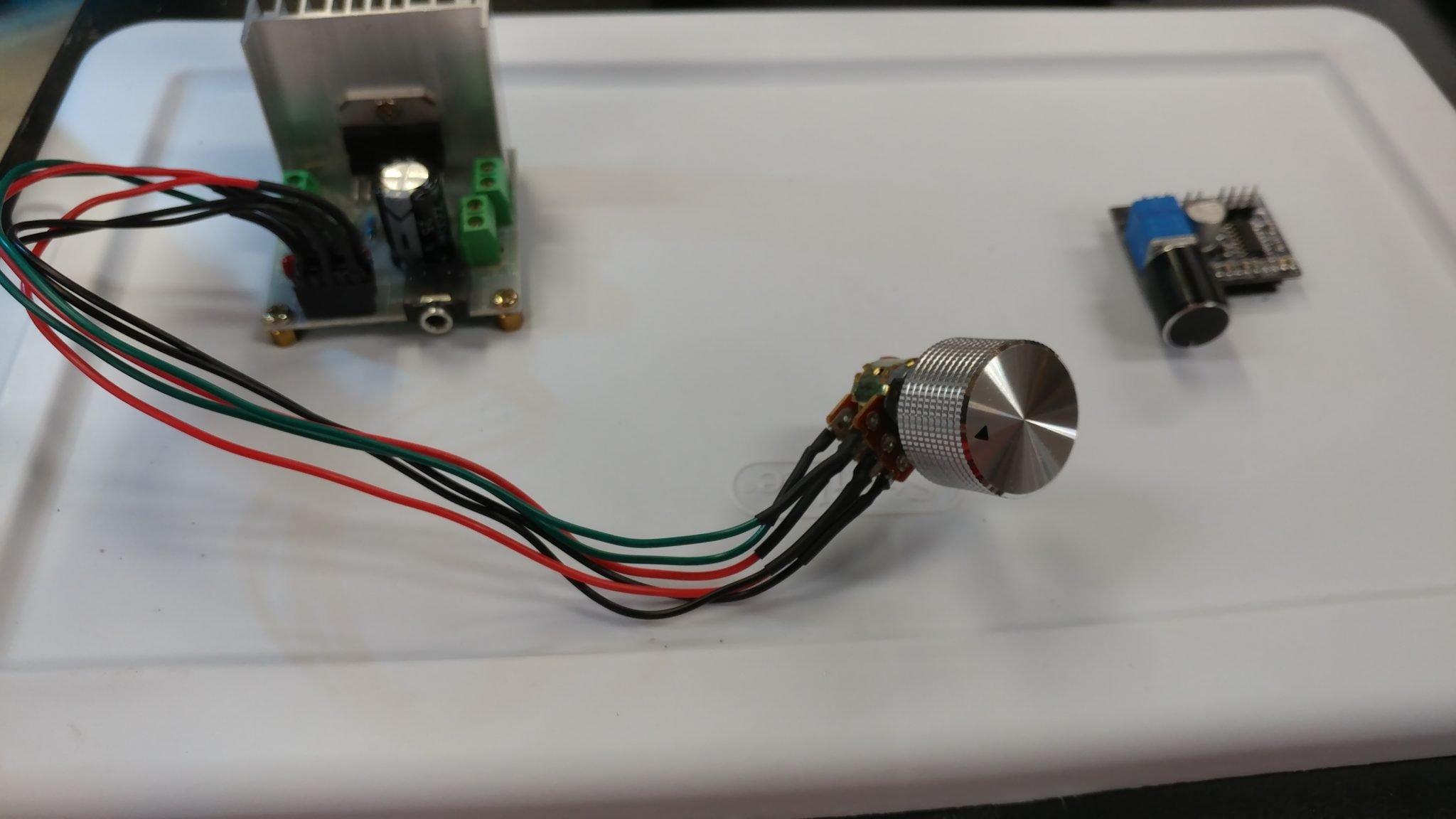
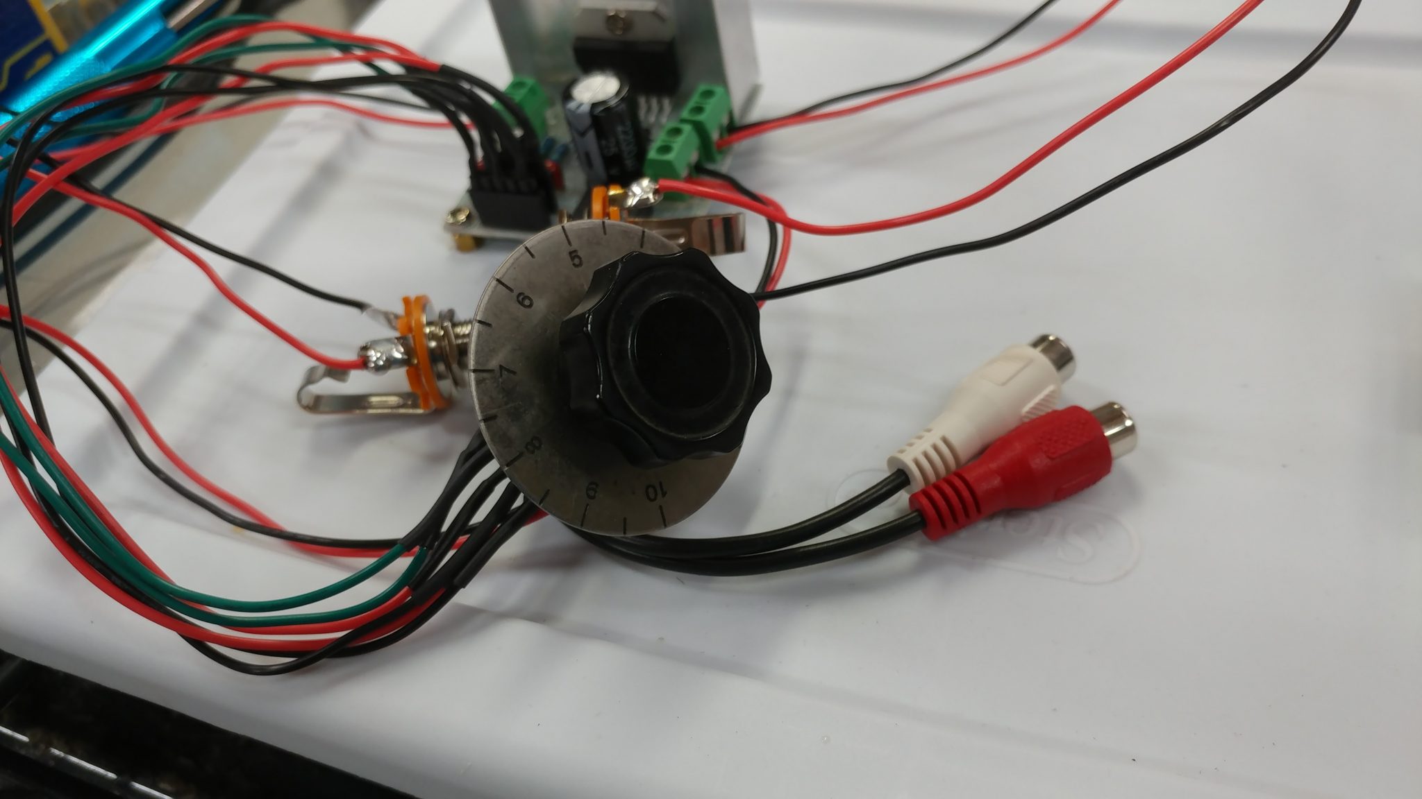
I also found an older knob that I attached to the potentiometer which I thought looked a little better than the one I was using.
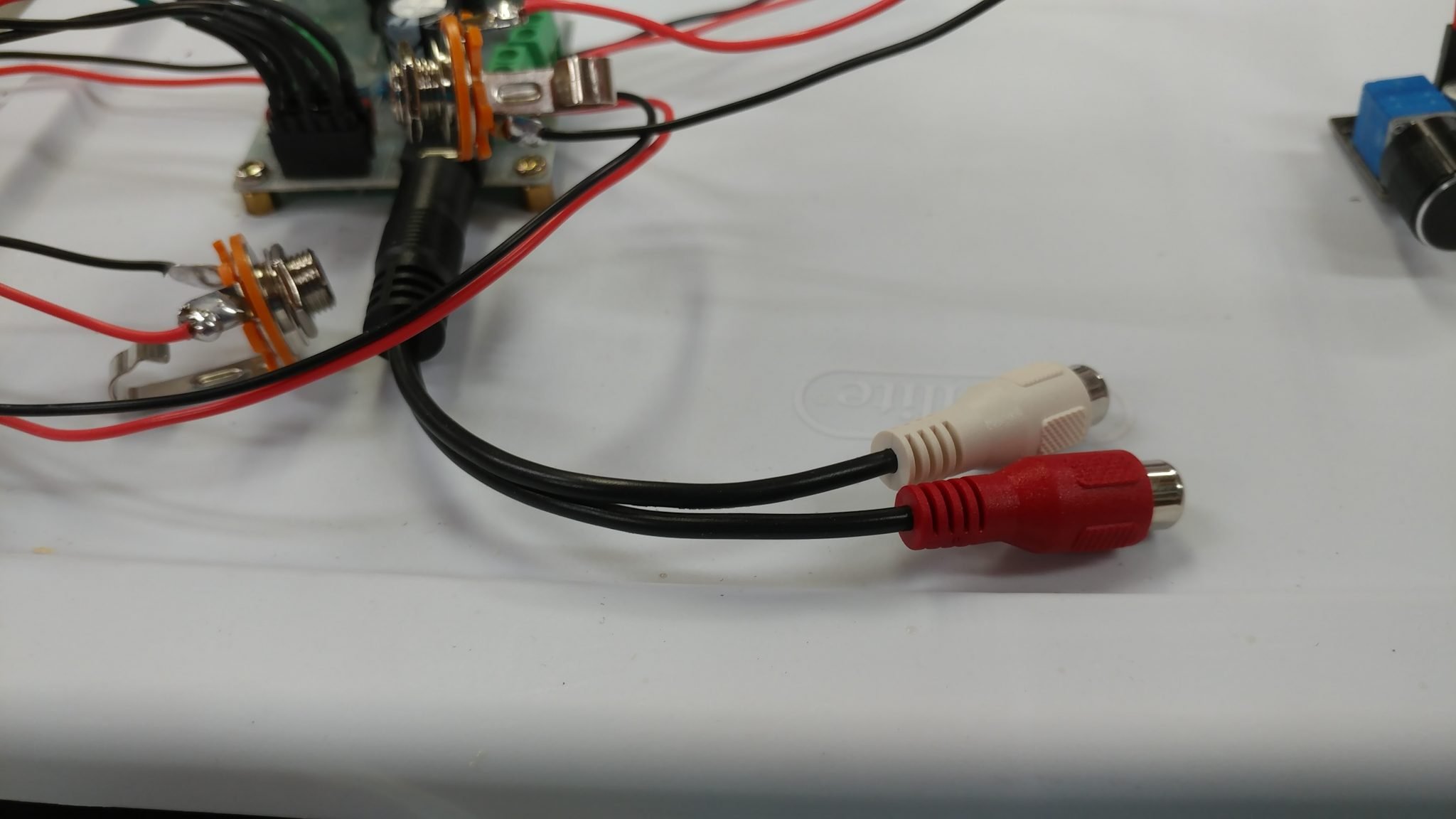
The signal both going out of the input amp and into the output amp will require RCA jacks. I have a pair for each board.
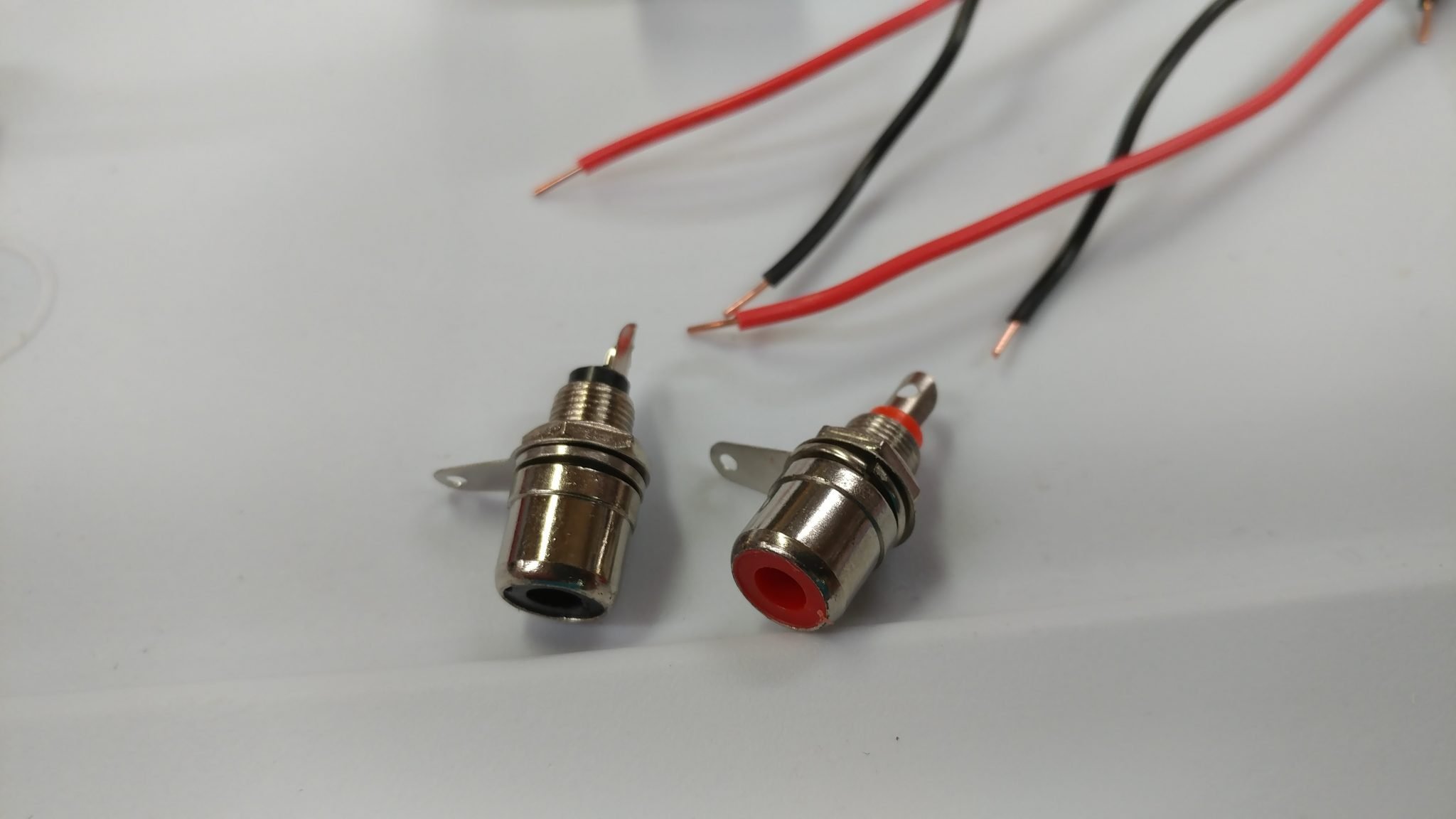
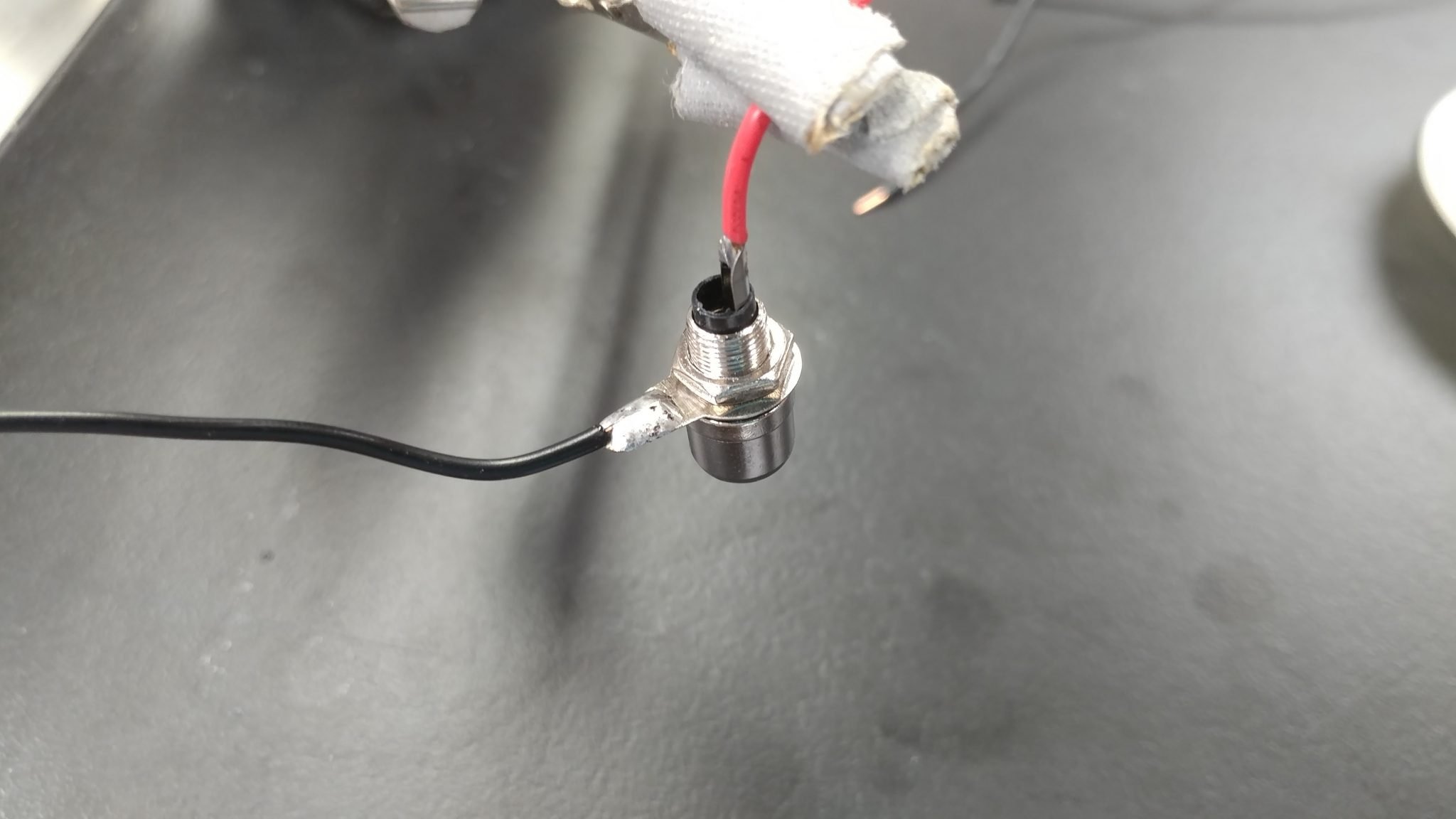
I soldered the wires to the tabs on each jack.
I made four of these, with two of them having plugs for connecting to the header pins on the input amp.
The input amp now has power and a way to send a signal out to the reverb tanks. Now I need to get a signal into it.
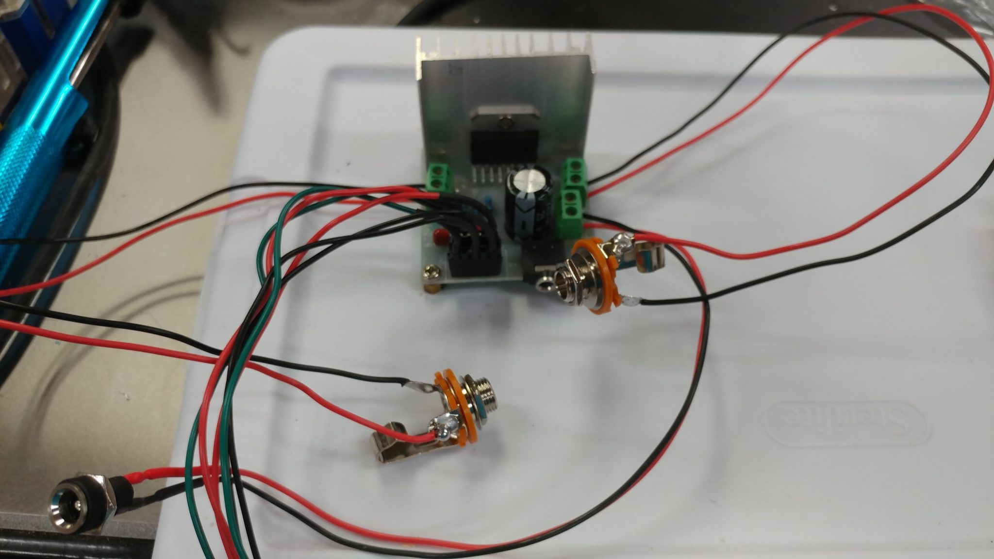
The input amp accepts a stereo signal but both channels share a common ground so I shortened the ground wire on one of the 1/4″ TS jacks so I could attach it to the ground tab on the other jack…
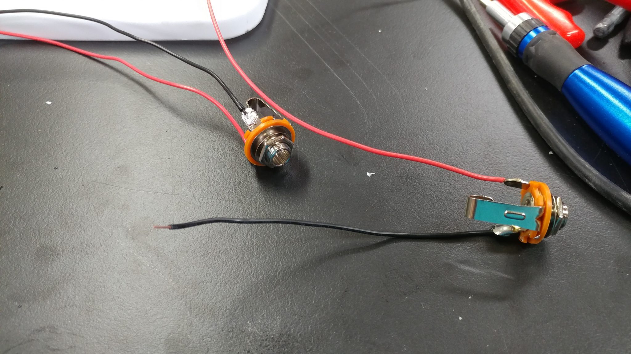
…which I did.
I then attached a three-hole plug to attach the input connectors to the input amp.
The input amp is now all wired up.
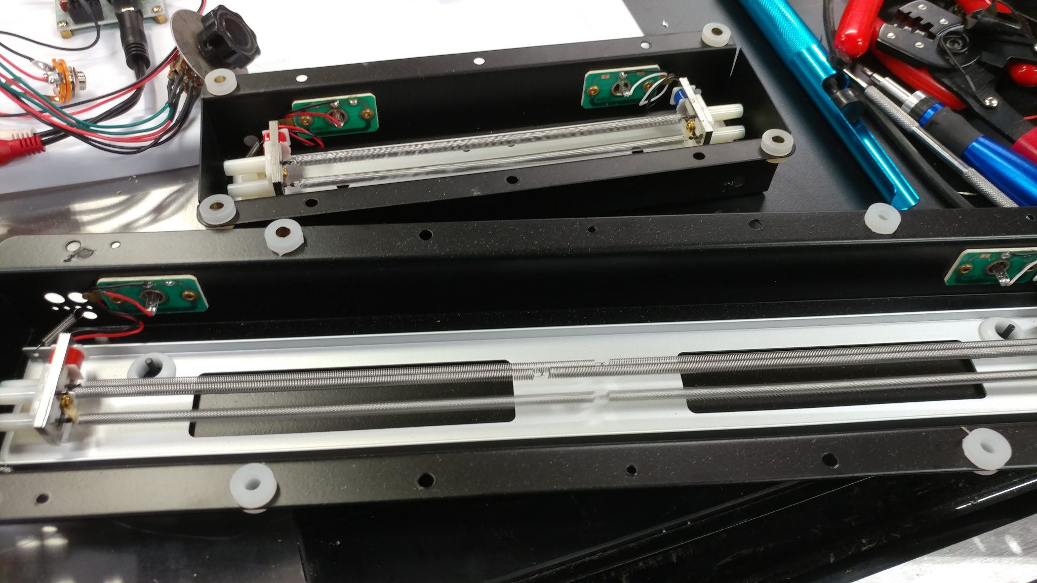
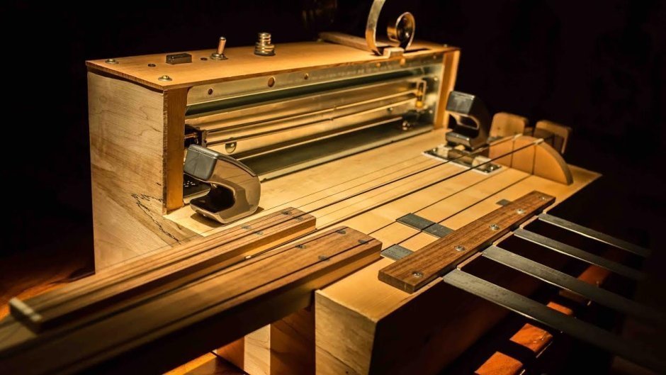
I am using two different reverb tanks. According to their spec sheets, the shorter one actually has a longer decay than the longer one. They both take a single audio signal in through an RCA jack and spit it out the other end through another RCA jack.
I used a standard stereo RCA cable to connect to the output jacks from the input amp. I then connected each end to a separate reverb tank.
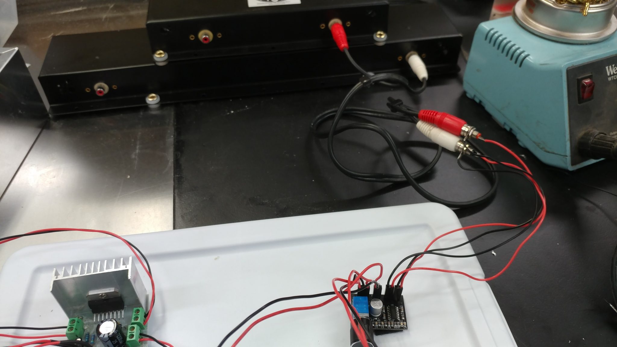
I then used another stereo RCA cable to connect the output from the reverb tanks to the input jacks of the output amp.
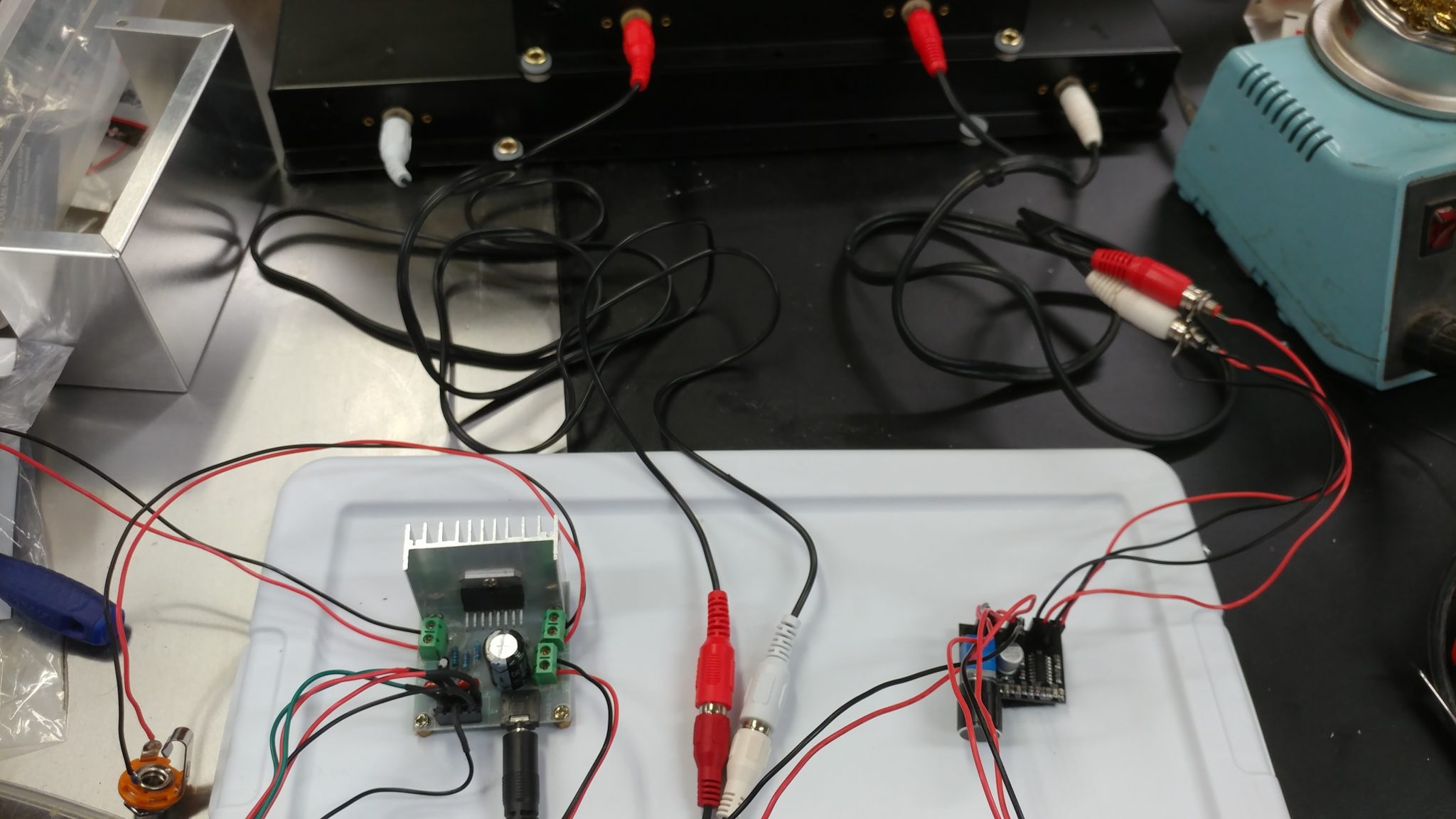
I then turned everything on and tested it out.
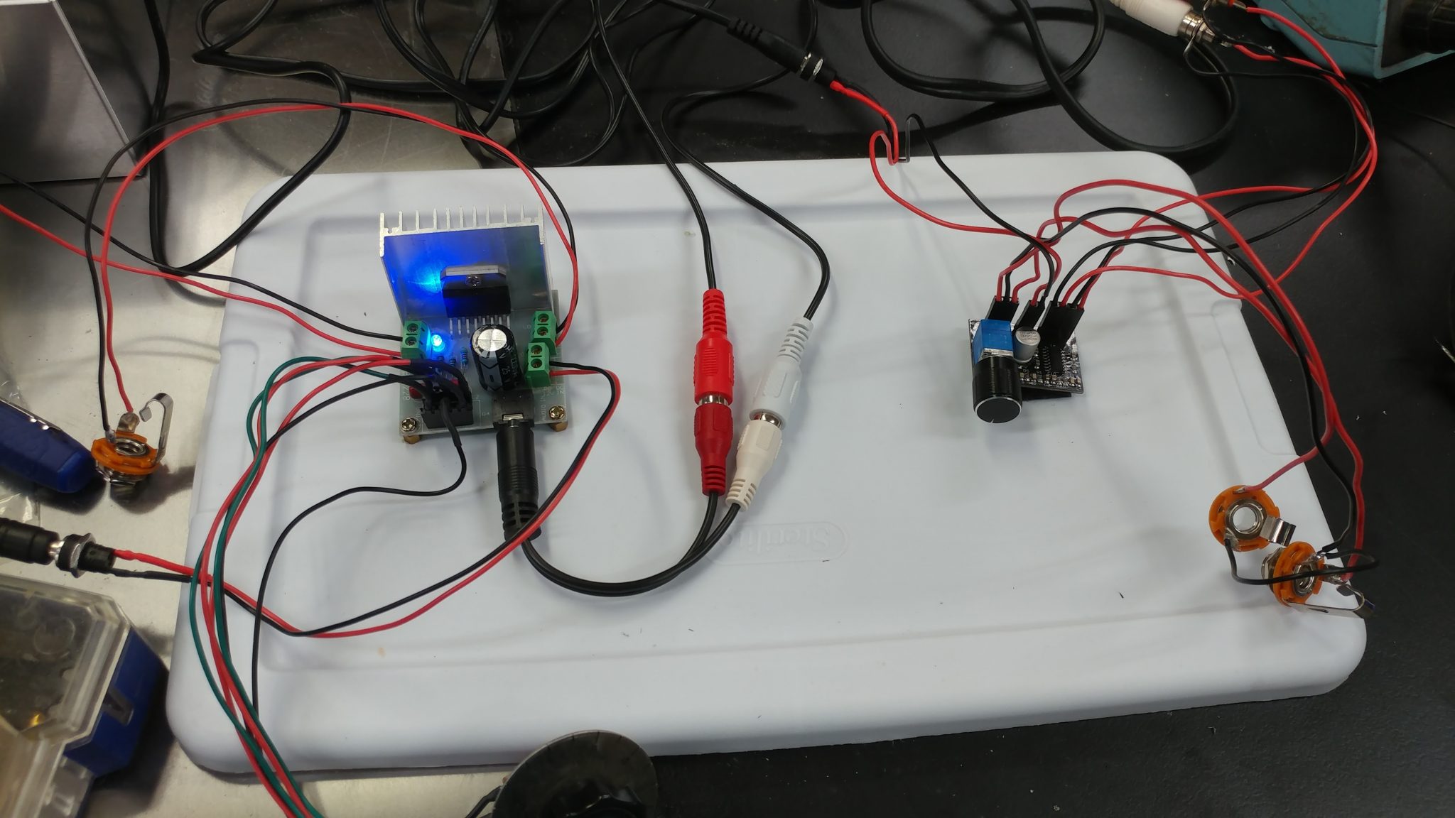
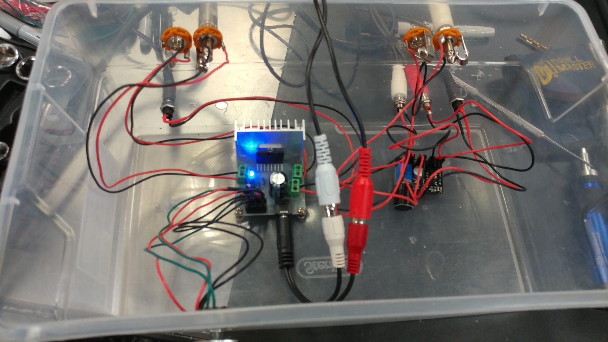
The good news is that it works and nothing exploded. The bad news is that when I attached the wires from the output amp to the volume potentiometer, I basically made a little radio. When the volume is maxed out, it has a pretty loud buzz. As soon as I lower the volume, it starts to pick up radio stations.
I tried hooking up another identical amp but without the potentiometer removed and it sounds great. I tried adding ferrites to the wires to see if that would help but it doesn’t. I’m going to have to try something else.
To make it easier to test with, I relocated everything to the inside of another storage bin.

 Many years ago I created a Windows program that would play random sound effects. I packed it full of public domain sounds that I found online, along with a few that I made myself.